ARRANGEMENT IN TIRE RETREADING ROLLING MACHINE FOR TIRES RECAPPING
US20110232848A1
2011-09-29
13/025,248
2011-02-11
Abstract:
The present disclosure relates to an arrangement in a tire retreading rolling machine including a structure composed of a lower frame (Q) provided with adjustable feet (P) and one column (C) on one of its vertices. Column (C) has on its outer side a motoreducer set (MR) which rotates a hub (CB) positioned on the column inner side. A bearing (M) held to column (C) supports the hub (CB) shaft, on which the tire to be processed is mounted. The rolling device mounted on the frame (Q) comprises arms (1) with end rolls (2), on which the tire is rested on the wheeling position. The rolls (2) press the new tread against the tire carcass, expelling the air that may have been trapped. The arms (1) are centrally pivoting in transversal gears (3), by the action of cylinders (4), allowing to get rolls (2) closer or farther to/from the new tread applied to the tire carcass. Secondary rolls (5) with semi-spherical shape, are positioned on the arms ends (1) from the outside, and close to the main rolls (2), so as to exert pressure also on the tread sides, next to the tire shoulder. A horizontal spindle (6) is driven by a motor (7) and reducer (8) set, and is intended to move the arms (1), making the secondary rolls (5) exert pressure against the tire shoulders. The gears (3) are mounted over the bearings (9) sliding on the machine busbars (10), causing the rolls (2) and the secondary rolls (5) to exert pressure throughout the tread, including the shoulders area.
Interested in similar patents?
Get notified when new applications in this technology area are published.
Classification:
B29D30/58 » CPC main
Producing pneumatic or solid tyres or parts thereof; Pneumatic tyres or parts thereof (e.g. produced by casting, moulding, compression moulding, injection moulding, centrifugal casting); Unvulcanised treads, e.g. on used tyres; Retreading Applying bands of rubber treads, i.e. applying camel backs
B29D30/16 » CPC further
Producing pneumatic or solid tyres or parts thereof; Pneumatic tyres or parts thereof (e.g. produced by casting, moulding, compression moulding, injection moulding, centrifugal casting); Building tyres on round cores, i.e. the shape of the core is approximately identical with the shape of the completed tyre Applying the layers; Guiding or stretching the layers during application
B29D30/28 » CPC further
Producing pneumatic or solid tyres or parts thereof; Pneumatic tyres or parts thereof (e.g. produced by casting, moulding, compression moulding, injection moulding, centrifugal casting); Building tyres by the flat-tyre method, i.e. building on cylindrical drums Rolling-down or pressing-down the layers in the building process
B29D30/30 » CPC further
Producing pneumatic or solid tyres or parts thereof; Pneumatic tyres or parts thereof (e.g. produced by casting, moulding, compression moulding, injection moulding, centrifugal casting); Building tyres by the flat-tyre method, i.e. building on cylindrical drums Applying the layers; Guiding or stretching the layers during application
B29D30/00 IPC
Producing pneumatic or solid tyres or parts thereof
B32B37/00 IPC
Methods or apparatus for making layered products; Treatment of the layers or of the layered products
B32B37/00 IPC
Methods or apparatus for laminating, e.g. by curing or by ultrasonic bonding
Description
BACKGROUND OF THE INVENTION
The present utility model relates to a novel building arrangement introduced in a tire retreading rolling machine used for tires recapping.
During the tires recapping process, an operation named rolling is performed, which consists in applying pressure for adhering a new tread to the carcass of the tire being recovered. While this operation is performed, the air that might be trapped between the tread and the tire carcass must be totally expelled. Otherwise, perfect parts adhesion will not occur, causing loss of tread parts during vehicle running.
Conventional tire retreading rolling machines are machines equipped with a rotating device, which receives a rim to which a tire carcass is mounted, with a tread already applied to it, and an arm with an extreme roll pressing the tread center strip against the tire carcass, thereby expelling the air that might have been trapped between the layers.
Examples of tire retreading rolling machines are found in patent documents MU 7400795-5, MU 7800332-6 and MU 8700907-2.
However, the operation of the tire retreading rolling machines is limited to the tread center strip, thus, proper pressing of the tire shoulder does not occur, i.e., the transition between the tire tread and flank. Such fact may result in failing adhesion on that tire area, jeopardizing the recapping process.
SUMMARY OF THE INVENTION
Thus, an objective of the present utility model is a novel building arrangement introduced in a tire retreading rolling machine, overcoming said limitations in the state-of-the-art. The arrangement in the tire retreading rolling machine comprises, in addition to conventional rolls, a pair of secondary rolls, having a semi-spherical shape, which are laterally positioned, in such a way to exert transversal pressure on the tread. Secondary spherical rolls perform more accurate and smoother rolling on tire shoulders area, where the tread thickness is thinner, requiring smoother rolling with more directed outline. Thus, it is possible to apply appropriate pressure to all parts of the tread, minimizing the lack of adhesion problem in the tire carcass.
BRIEF DESCRIPTION OF THE DRAWINGS
The arrangement in the tire retreading rolling machine proposed by the present utility model, is hereon described in detail, based on the enclosed drawings, listed below:
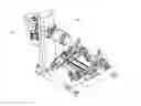
FIG. 1—perspective of the tire retreading rolling machine incorporating the rolling device;
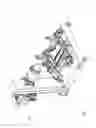
FIG. 2—perspective of the rolling device isolated from the machine;
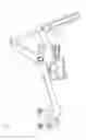
FIG. 3—front view of the rolling device;
FIG. 4—left side view of the rolling device;
FIG. 5—right side view of the rolling device;
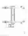
FIG. 6—upper view of the rolling device;
FIG. 7—lower view of the rolling device.
DESCRIPTION OF PREFERRED EMBODIMENTS
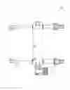
FIG. 1 shows the tire retreading rolling machine comprising the rolling device object of the present utility model and comprising a structure composed of a lower frame (Q) provided with adjustable feet (P) and one column (C) on one of its vertices. The column (C) has on its outer side a motoreducer set (MR) which rotates a hub (CB) positioned on the column inner side. A bearing (M), held to the column (C), supports the hub (CB) shaft, on which the tire to be processed is mounted.
FIGS. 2 to 7 show the rolling device mounted on the frame (Q) comprising arms (1) with end rolls (2), on which the tire is rested on the wheeling position (not shown). The rolls (2) press the new tread against the tire carcass, expelling the air that may have been trapped. The arms (1) are centrally pivoting in transversal gears (3), by the action of hydraulic or pneumatic cylinders (4), allowing to get rolls (2) closer or farther to/from the new tread applied to the tire carcass.
Secondary rolls (5) with semi-spherical shape, are positioned on the arms ends (1) from the outside, and close to the main rolls (2), so as to exert pressure also on the tread sides, next to the tire shoulder.
A horizontal spindle (6) is driven by a motor (7) and reducer (8) set, and is intended to move the arms (1), making the secondary rolls (5) exert pressure against the tire shoulders. The gears (3) are mounted over the bearings (9) sliding on the machine busbars (10), causing the rolls (2) and the secondary rolls (5) to exert pressure throughout the tread, including the shoulders area.
Claims
What is claimed is:1. An arrangement in tire retreading rolling machine for tires recapping, comprising a structure composed of a lower frame provided with adjustable feet and one column on one of its vertices, and column has on its outer side a motoreducer set which rotates a hub positioned on the column inner side, with bearing held to column and supporting the hub shaft, on which the tire to be processed is mounted, wherein it comprises
arms with end rolls, on which the tire is rested on the wheeling position, with the arms centrally pivoting in transversal gears, by the action of cylinders;
secondary rolls with semi-spherical shape, positioned on the arms ends from the outside, and close to the main rolls, so as to press the tread sides, next to the tire shoulder;
a horizontal spindle, driven by a motor and reducer set, to get arms closer to the secondary rolls against the tread and the tire shoulders area;
the transversal gears are mounted over the bearings sliding on the machine busbars.
Images & Drawings included:


Sources:
- United States Patent and Trademark Office - verify current appl. status at the USPTO↗
Recent applications in this class:
- » 20220063225 2022-03-03
METHOD AND APPARATUS FOR MEASURING RADIAL FORCE DURING TIRE BUILDING - » 20180099466 2018-04-12
Stiffness enhanced tread element - » 20170348934 2017-12-07
Methods and apparatus for installing a tread ring upon a tire carcass - » 20170050398 2017-02-23
METHOD OF TIRE TREAD PRODUCTION AND TIRE PRODUCED THEREBY - » 20140130961 2014-05-15
Methods and apparatus for installing a tread ring upon a tire carcass - » 20120318443 2012-12-20
PRODUCTION DEVICE OF RUBBER BAND BODY, PRODUCTION METHOD OF RUBBER BAND BODY, PRODUCTION DEVICE OF WINDING MEMBER OF RUBBER BAND BODY AND PRODUCTION OF WINDING MEMBER OF RUBBER BAND BODY - » 20120132330 2012-05-31
Stiffness enhanced tread element - » 20110030880 2011-02-10
METHOD FOR MANUFACTURING UNVULCANIZED TIRE AND APPARATUS FOR MANUFACTURING THE TIRE