HOUSING OF ELECTRONIC DEVICE AND METHOD FOR MAKING THE SAME
US20110234063A1
2011-09-29
12/909,949
2010-10-22
Abstract:
A housing of electronic device includes a main plate and a metal peripheral wall, the peripheral wall is fabricated by cold drawn and secured to the periphery of the main plate.
Inventors:
- Bin LI 24 🇨🇳 Shenzhen City, China
- Kai Shi 2 🇨🇳 Shenzhen City, China
- CHAO-HSUN LIN 4 🇹🇼 Shindian, Taiwan
Assignee:
- FIH (HONG KONG) LIMITED 1,461 🇭🇰 Kowloon, Hong Kong
- SHENZHEN FUTAIHONG PRECISION INDUSTRY CO., LTD. 1,108 🇨🇳 ShenZhen City, China
Interested in similar patents?
Get notified when new applications in this technology area are published.
Classification:
B23K26/244 » CPC main
Working by laser beam, e.g. welding, cutting or boring; Bonding by welding; Seam welding Overlap seam welding
B23K2103/05 » CPC further
Materials to be soldered, welded or cut; Iron or ferrous alloys; Steel or steel alloys Stainless steel
B23K2103/10 » CPC further
Materials to be soldered, welded or cut; Non-ferrous metals or alloys Aluminium or alloys thereof
B23K2103/14 » CPC further
Materials to be soldered, welded or cut; Non-ferrous metals or alloys Titanium or alloys thereof
B23K2103/15 » CPC further
Materials to be soldered, welded or cut; Non-ferrous metals or alloys Magnesium or alloys thereof
B23K2103/18 » CPC further
Materials to be soldered, welded or cut Dissimilar materials
B23K2103/20 » CPC further
Materials to be soldered, welded or cut; Dissimilar materials Ferrous alloys and aluminium or alloys thereof
B23K2103/24 » CPC further
Materials to be soldered, welded or cut; Dissimilar materials Ferrous alloys and titanium or alloys thereof
B23K2103/42 » CPC further
Materials to be soldered, welded or cut; Organic material Plastics
Y10T29/49826 » CPC further
Metal working; Method of mechanical manufacture Assembling or joining
Y10T29/49833 » CPC further
Metal working; Method of mechanical manufacture; Assembling or joining Punching, piercing or reaming part by surface of second part
H05K5/00 IPC
Casings, cabinets or drawers for electric apparatus
H05K5/00 IPC
Casings, cabinets or drawers for electric apparatus
B32B37/16 IPC
Methods or apparatus for laminating, e.g. by curing or by ultrasonic bonding characterised by the properties of the layers with all layers existing as coherent layers before laminating
B23P11/00 IPC
Connecting or disconnecting metal parts or objects by metal-working techniques not otherwise provided for
B23P19/00 IPC
Machines for simply fitting together or separating metal parts or objects, or metal and non-metal parts, whether or not involving some deformation ; Tools or devices therefor so far as not provided for in other classes
B23K26/00 IPC
Working by laser beam, e.g. welding, cutting or boring
Description
BACKGROUND
1. Technical Field
The present disclosure relates to a housing of electronic device and a method for making the housing.
2. Description of Related Art
Metal housing of electronic device can be fabricated by punching. However, the punching to the housing may form rough rims at the periphery, and accordingly needs an additional process to remove the rough rims.
Therefore, there is room for improvement within the art.
BRIEF DESCRIPTION OF THE DRAWINGS
Many aspects of the present housing of electronic device and method for making the same can be better understood with reference to the following drawings. The components in the various drawings are not necessarily drawn to scale, the emphasis instead being placed upon clearly illustrating the principles of the present disclosure. Moreover, in the drawings, like reference numerals designate corresponding parts throughout the diagrams.
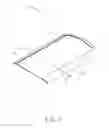
FIG. 1 is a schematic view of a housing of electronic device according to an exemplary embodiment.
FIG. 2 is a cross-sectional schematic view of the housing shown in FIG. 1.
DETAILED DESCRIPTION
FIGS. 1 and 2 show a housing 10 of an electronic device, such as a mobile phone or a personal digital assistant according to an exemplary embodiment. The housing 10 includes a main plate 11 and a peripheral wall 13. The peripheral wall 13 connects to and surrounds the main plate 11.
The main plate 11 may be made of metal such as stainless steel, stainless steel alloy, aluminum, aluminum alloy, magnesium, magnesium alloy, titanium, titanium alloy etc. The main plate 11 also can be made of one or more impact resistant and wear resistant plastic materials selected from a group including polycarbonate (PC), Polymethyl Methacrylate (PMMA), and Polyamide (PA). The main plate 11 includes a main section 111 with a flange 113 formed on a portion of the periphery of the main section 111. In the present embodiment, the main section 111 is planar and the flange 113 is curved. The thickness of the main section 111 may be about 0.2 millimeter (mm) to about 0.3 mm, and the thickness of the flange 113 may be about 0.15 mm.
The peripheral wall 13 is also curved and connects to the flange 113 of the main plate 11. The peripheral wall 13 may be made of metal such as stainless steel, stainless steel alloy, aluminum, aluminum alloy. The peripheral wall 13 can be cold drawn. In the present embodiment, the thickness of the peripheral wall 13 may be about 0.5 mm.
The peripheral wall 13 can be connected to the main plate 11 by laser welding. During welding, the peripheral wall 13 is aligned with and abuts the flange 113 of the main plate 11. The adjoining area of the peripheral wall 13 and the flange 113 is heated and melted by a laser and cooled to secure the peripheral wall 13 to the flange 113. In other embodiments, the peripheral wall 13 can be curved in such a way as to be able to hook to the main plate 11.
In other embodiments, to save on material when strength is less important the flange 113 of the main plate 11 can be omitted, and the peripheral wall 13 directly connected to the periphery of the main section 111.
A method to make the housing 10 includes following steps.
The main plate 11 is provided and can be fabricated by, for example, punching a sheet metal or injection molding a plastic material. The main plate 11 includes the main section 111 and the flange 113.
A metal material is provided and processed by cold drawing to form the peripheral wall 13.
The peripheral wall 13 is positioned on the flange 113 of the main plate 11, and a portion of the peripheral wall 13 substantially abuts the flange 113. The adjoining area of the peripheral wall 13 and the flange 113 is heated and melted by a laser and then cooled to secure the peripheral wall 13 with the flange 113. Therefore, the housing 10 can be made.
It is to be understood that even though numerous characteristics and advantages of the present embodiments have been set forth in the foregoing description, together with details of structures and functions of various embodiments, the disclosure is illustrative only, and changes may be made in detail, especially in matters of shape, size, and arrangement of parts within the principles of the present invention to the full extent indicated by the broad general meaning of the terms in which the appended claims are expressed.
Claims
What is claimed is:1. A housing of electronic device, comprising:
a main plate;
a metal peripheral wall; wherein:
the peripheral wall is cold drawn and secured to the periphery of the main plate.
2. The housing of electronic device as claimed in claim 1, wherein the main plate is punched sheet metal.
3. The housing of electronic device as claimed in claim 2, wherein the metal includes stainless steel, stainless steel alloy, aluminum, aluminum alloy, magnesium, magnesium alloy, titanium, titanium alloy.
4. The housing of electronic device as claimed in claim 1, wherein the main plate includes a main section with a flange formed on a portion of the periphery of the main section, the peripheral wall is secured with the flange.
5. The housing of electronic device as claimed in claim 4, wherein the main section has a thickness in the range of about 0.2 mm (millimeter) to about 0.3 mm, the edging having a thickness of about 0.15 mm.
6. The housing of electronic device as claimed in claim 1, wherein the peripheral wall can be made of metal including stainless steel, stainless steel alloy, aluminum, aluminum alloy.
7. The housing of electronic device as claimed in claim 1, wherein the peripheral wall is secured to the main plate by laser welding.
8. The housing of electronic device as claimed in claim 1, wherein the main plate is formed by injection molding a plastic material.
9. The housing of electronic device as claimed in claim 8, wherein the plastic material is selected from a group including polycarbonate (PC), Polymethyl Methacrylate (PMMA), and Polyamide (PA).
10. A method for making a housing of electronic device, comprising:
providing a main plate;
providing a metal material, cold drawing the metal material to form a peripheral wall;
securing the peripheral wall to the periphery of the main plate to form the housing.
11. The method for making the housing of electronic device as claimed in claim 10, wherein the main plate is formed by punching a metal material.
12. The method for making the housing of electronic device as claimed in claim 10, wherein the main plate is formed by injection molding a plastic material.
13. The method for making the housing of electronic device as claimed in claim 10, wherein the peripheral wall is secured to the main plate by laser welding.
14. The method for making the housing of electronic device as claimed in claim 10, wherein main plate includes a main section with a flange integrally formed on a portion of the periphery of the main section, the peripheral wall is secured to the flange.
Images & Drawings included:


Sources:
- United States Patent and Trademark Office - verify current appl. status at the USPTO↗
Similar patent applications:
- » 20130257237
Housing for electronic devices and method for making housing - » 20200094518
THIN, HIGH-STIFFNESS LAMINATES, PORTABLE ELECTRONIC DEVICE HOUSINGS INCLUDING THE SAME, AND METHODS FOR MAKING SUCH LAMINATES AND PORTABLE ELECTRONIC DEVICE HOUSINGS - » 20100108344
Housing for electronic device and method of making the housing - » 20090305001
HOUSING FOR ELECTRONIC DEVICE AND METHOD FOR MAKING THE HOUSING - » 20140368388
HOUSING OF ELECTRONIC DEVICE, AND METHOD FOR MAKING THE HOUSING - » 20090009935
HOUSING FOR AN ELECTRONIC DEVICE AND METHOD FOR MAKING THE HOUSING - » 20120189842
ELECTRONIC DEVICE HOUSING AND METHOD FOR MAKING THE SAME - » 20130240350
ELECTRONIC DEVICE HOUSING AND METHOD FOR MAKING THE SAME - » 20110159258
Electronic device housing and method for making the same - » 20060092601
Method of making an electronic device housing
Recent applications in this class:
- » 20250162076 2025-05-22
Laser Welding Method, Terminal Joint Structure, and Power Conversion Device - » 20250162075 2025-05-22
LASER-BEAM WELDING METHOD - » 20240367262 2024-11-07
METHOD FOR WELDING ZINC-COATED SHEETS - » 20240326169 2024-10-03
LASER WELDING METHOD - » 20240227079 2024-07-11
LASER BEAM JOINING METHOD - » 20240165743 2024-05-23
Method For Laser Welding - » 20240165742 2024-05-23
LASER-BASED DEEP WELDING METHOD - » 20240131627 2024-04-25
LASER BEAM JOINING METHOD - » 20240082954 2024-03-14
BIPOLAR PLATE FOR A FUEL CELL AND PROCESS FOR WELDING A BIPOLAR PLATE - » 20240075555 2024-03-07
LASER WELDING METHOD
Recent applications for this Assignee:
- » 20220140846 2022-05-05
Antenna structure and wireless communication device using same - » 20220094077 2022-03-24
Antenna structure and wireless communication device using same - » 20220059931 2022-02-24
Antenna structure and wireless communication device - » 20220021116 2022-01-20
Single antenna structure capable of operating in multiple band widths - » 20220010948 2022-01-13
Anti-loosing structure and backlight module - » 20200170133 2020-05-28
Housing, electronic device, and method for manufacturing same - » 20200122194 2020-04-23
Frame and surface treatment method for the frame - » 20200060034 2020-02-20
Housing, method for manufacturing the same, and electronic device having the same - » 20200016805 2020-01-16
Housing, electronic device, and method for manufacturing the same - » 20190368052 2019-12-05
COMPOSITE AND METHOD FOR MAKING SAME