Method and device for automatically adapting a reference image
US20110235876A1
2011-09-29
13/053,623
2011-03-22
✅ Patent granted
US 8,929,631 B2
2015-01-06
-
-
Randolph I Chu | Nathan Bloom
2033-06-02
Abstract:
A method and a device for reference image adapting in the field of fluoroscopy-controlled interventional repair of abdominal aortic aneurisms on angiography systems are proposed. Displacements which can be brought about as a result of introducing instruments, such as when a stent is deployed in an aorta, are automatically corrected. It is also possible to correct such displacements which initially cannot be perceived in the image due to the angle of view.
Inventors:
- Marcus Pfister 116 🇩🇪 Bubenreuth, Germany
- Martin Von Roden 1 🇺🇸 Aurora, OH, United States
Assignee:
- SIEMENS AKTIENGESELLSCHAFT 12,417 🇩🇪 Munich, Germany
Applicant:
Interested in similar patents?
Get notified when new applications in this technology area are published.
Classification:
G06T7/30 » CPC further
Image analysis Determination of transform parameters for the alignment of images, i.e. image registration
G16H50/20 » CPC further
ICT specially adapted for medical diagnosis, medical simulation or medical data mining; ICT specially adapted for detecting, monitoring or modelling epidemics or pandemics for computer-aided diagnosis, e.g. based on medical expert systems
A61B34/20 » CPC further
Computer-aided surgery; Manipulators or robots specially adapted for use in surgery Surgical navigation systems; Devices for tracking or guiding surgical instruments, e.g. for frameless stereotaxis
A61B2034/2065 » CPC further
Computer-aided surgery; Manipulators or robots specially adapted for use in surgery; Surgical navigation systems; Devices for tracking or guiding surgical instruments, e.g. for frameless stereotaxis; Tracking techniques Tracking using image or pattern recognition
A61B2090/363 » CPC further
Instruments, implements or accessories specially adapted for surgery or diagnosis and not covered by any of the groups - , e.g. for luxation treatment or for protecting wound edges; Image-producing devices or illumination devices not otherwise provided for Use of fiducial points
A61B6/5211 » CPC further
Apparatus for radiation diagnosis, e.g. combined with radiation therapy equipment; Devices using data or image processing specially adapted for radiation diagnosis involving processing of medical diagnostic data
G06T2207/30048 » CPC further
Indexing scheme for image analysis or image enhancement; Subject of image; Context of image processing; Biomedical image processing Heart; Cardiac
G06T2207/10121 » CPC further
Indexing scheme for image analysis or image enhancement; Image acquisition modality; X-ray image Fluoroscopy
G06T2207/30021 » CPC further
Indexing scheme for image analysis or image enhancement; Subject of image; Context of image processing; Biomedical image processing Catheter; Guide wire
G06T2207/10081 » CPC further
Indexing scheme for image analysis or image enhancement; Image acquisition modality; Tomographic images Computed x-ray tomography [CT]
A61B6/504 » CPC main
Apparatus for radiation diagnosis, e.g. combined with radiation therapy equipment; Clinical applications involving diagnosis of blood vessels, e.g. by angiography
G06K9/00 IPC
Methods or arrangements for recognising patterns
A61F2/82 » CPC further
Filters implantable into blood vessels; Prostheses, i.e. artificial substitutes or replacements for parts of the body; Appliances for connecting them with the body; Devices providing patency to, or preventing collapsing of, tubular structures of the body, e.g. stents Devices providing patency to, or preventing collapsing of, tubular structures of the body, e.g. stents
A61B6/487 » CPC further
Apparatus for radiation diagnosis, e.g. combined with radiation therapy equipment; Diagnostic techniques involving generating temporal series of image data involving fluoroscopy
A61B6/5247 » CPC further
Apparatus for radiation diagnosis, e.g. combined with radiation therapy equipment; Devices using data or image processing specially adapted for radiation diagnosis involving processing of medical diagnostic data combining image data of a patient, e.g. combining a functional image with an anatomical image combining images from an ionising-radiation diagnostic technique and a non-ionising radiation diagnostic technique, e.g. X-ray and ultrasound
A61B5/05 IPC
Measuring for diagnostic purposes ; Identification of persons Detecting, measuring or recording for diagnosis by means of electric currents or magnetic fields; Measuring using microwaves or radio waves
A61B6/00 IPC
Apparatus for radiation diagnosis, e.g. combined with radiation therapy equipment
G06T7/00 IPC
Image analysis
Description
CROSS REFERENCE TO RELATED APPLICATIONS
This application claims priority of German application No. 10 2010 012 621.7 filed Mar. 24, 2010, which is incorporated by reference herein in its entirety.
FIELD OF THE INVENTION
The invention relates to the field of fluoroscopy-controlled interventional repair of abdominal aortic aneurisms (=AAA) on angiography systems.
BACKGROUND OF THE INVENTION
An abdominal aortic aneurism is a dilatation of a vessel on the abdominal aorta. This condition is treated by insertion of a so-called stent graft, i.e. composite angioplasty devices. Guide wires and catheters are inserted into the aorta via both groins and one or more stent grafts are introduced via said guide wires and catheters. An abdominal aortic aneurism A of this type is shown by way of example in FIG. 1a. It is treated by insertion of a stent graft S. Guide wires and/or catheters K are inserted into the aorta via both groins and the stent grafts are introduced with the aid of said guide wires and catheters.
The aim when inserting said stent grafts is to place the “landing zone” of the vascular graft as far as possible in the healthy vessel wall region, though at the same time taking care that no important branch vessels are covered. In particular the branches of the renal arteries, of the superior mesenteric artery (arteria mesenterica superior), of the truncus coeliacus, and of the internal iliac arteries (a. iliaca interna) must be kept free. A sensitive point is the placement of the “main stent” in the aorta, in which case the cited branch vessels must not be occluded. In the case of complex stents which include the leg arteries, as shown for example in FIG. 1c, the final stent must sometimes be composed of “partial stents” (e.g. an aortic stent (I) to which the stent for the leg artery (II) is attached through what is termed a fenestration).
In order to avoid the necessity of injecting contrast agent to allow constant vessel visualization for monitoring purposes during the complex stent positioning procedure it is possible to overlay a reference image (anatomically correctly) in the manner of a positioning aid, which reference image renders the vessels (in this case aorta and branch vessels). As shown in FIG. 2a, said reference image can either be a 2D angiogram (DSA) or, as shown in FIG. 2b, it can beneficially be a previously recorded 3D dataset (e.g. a CT angiography sequence) of the aneurysm. These show more details and can be overlaid at any angulation of the C-arm.
As shown in FIG. 3, it is possible to pre-segment the aneurysm from the reference images. In this case the course of the vessel (centerline) or the contours of the vessels can be determined, for example. This can happen both in the case of the 2D reference image, as shown in FIG. 3a, and in the case of the 3D reference image, as shown in FIG. 3b. Furthermore it is possible to identify and track instruments (e.g. catheters or guidance devices) in 2D images. As already shown in FIG. 2, a partially flexible 2D-3D or 3D-3D registration, e.g. of 2D and 3D angiography images, is possible.
A problem with said overlays is that the reference image (2D or 3D) shows the vessel anatomy at a specific instant in time. If, as shown e.g. in FIG. 4, the physician introduces very inflexible or rigid instruments, e.g. a catheter K, the anatomy is deformed. If said deformation is not corrected in the overlaid reference image (see FIGS. 4a and 4b), an imprecision or a discrepancy arises when the reference image is superimposed. This can lead to uncertainties in navigation during an intervention in which the overlay serves as a navigation aid.
SUMMARY OF THE INVENTION
As mentioned in the introduction, it is the object of the invention to correct deformations of said kind.
The object is achieved by means of the method and the device as claimed in the independent claims. Advantageous embodiments of the method and of the device are the subject matter of the dependent claims or can be derived from the following description and the exemplary embodiments.
The subject matter of the invention is a method for adapting at least one reference image, suitable in particular for inserting a stent into an aorta, which automatically corrects displacements which can be brought about as a result of introducing instruments, e.g. a catheter. At the same time it is preferred if displacements of the kind which initially cannot be perceived or are not visible in the image at corresponding viewing angles can also be corrected.
A further aspect of the invention is a device for the above-described adapting method, the device having means for performing the said adaption. The embodiment variants characterized in the dependent claims in relation to a method according to the invention also apply in respect of the device according to the invention.
The invention thereby increases the precision in the overlaid reference image which serves as a navigation aid during a medical intervention.
BRIEF DESCRIPTION OF THE DRAWINGS
Further advantages, details and developments of the invention will emerge from the following description of exemplary embodiments in conjunction with the drawings, in which:
FIGS. 1, 2, 3 and 4 cited in the introduction show the possible prior art and the above-described problem of deformation, and
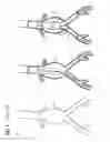
FIGS. 5a and 5b show the correction according to the invention in the image plane, and
FIGS. 6a, 6b and 6c show the correction according to the invention in a three-dimensional representation.
DETAILED DESCRIPTION OF THE INVENTION
In the following the principle of the correction according to the invention is described with reference to the repair of an aortic aneurysm in the following embodiment variants:
Ideally the following preconditions are established:
- 1. A reference dataset, registered with respect to the C-arm (or, as the case may be, the respective fluoroscopic images), which represents either a 3D volume, e.g. a previously performed CT angiography, or a C-arm CT recorded during the intervention, or else 2D images, e.g. angiography sequences (DSA) of the corresponding vessels,
- 2. information relating to the course (e.g. the so-called centerline) of the vessels or the course of vessel contours and/or other corresponding information, as shown for example in FIG. 3, in the reference images, e.g. relating to a (semi-)automatic 2D or 3D segmentation (depending on dataset used), and
- 3. a means of detecting and tracking the instrument(s) introduced, e.g. the instrument for introducing the stent. This can happen e.g. by way of a corresponding identification or tracking of the instruments in the fluoroscopic images.
As shown in FIG. 5, the procedure according to the invention is preferably performed in the following sequence:
-
- The position detected in the fluoroscopic image identifies the current course of the vessel, since the instrument is located inside the vessel.
- The reference image (or the centerline of the segmentation of the reference image) is then adapted (updated) accordingly or, as the case may be, distorted or, as the case may be, displaced or, as the case may be, deformed so that the current vessel course and assumed vessel course are consistent once again. In this case the corresponding part of the vessel in the reference image is brought into congruence with the current vessel course resulting from the position of the detected instrument, e.g. a catheter K, as shown for example in FIG. 5a. The reference image is adapted differently according to position and penetration depth of the instrument; see e.g. also FIG. 5b.
- The remainder of the vessel course (i.e. the part in which no instrument has yet been introduced) is extrapolated e.g. on the assumption of “smoothness conditions”, i.e. generally the vessels have no abrupt bends or similar. In this case regions remote from the detected instrument are not deformed (e.g. the renal arteries when an instrument is introduced into the leg arteries) and closer regions are deformed in such a way that a smooth vessel course is preserved.
- In the deformation of the reference image (in particular of a 3D vessel) attention can also be devoted in particular to a “trueness to length”, since an introduced instrument does not change the length of the centerline of the vessel. By way of these boundary conditions it is possible in particular to correct deviations which initially are not visible in the image on account of the viewing angle, as shown for example in FIG. 6a. If the vessel is e.g. curved “in the viewing direction”, i.e. perpendicular to the image plane, an introduced instrument initially creates no visible displacement between overlaid reference image and fluoroscopic image. However, if the curvature of the centerline is known by way of the segmentation, the stretching produced by the instrument can be computed and consequently e.g. the displacement of a branch vessel from its actual location computed, and the overlay can then be adapted accordingly, as shown for example in FIGS. 6b and 6c.
Optionally, the following embodiment variants are conceivable. The information relating to the course of the vessel (in 2D or in 3D)
-
- can also be defined manually by the user (e.g. by means of a marker),
- can also be given by means of a mathematical description, e.g. a higher-order polynomial or another suitable function. The overlay can then be adapted e.g. by way of the updating of the function parameters according to the position of the detected instrument.
Optionally or alternatively, the position of the introduced instrument can be
-
- defined manually by the user,
- determined via a position-transmitting sensor,
- determined or reconstructed three-dimensionally with the aid of two or more X-ray images from a number of angles.
It is advantageous that not just one, but a plurality of instruments are detected or tracked. This enables e.g. other stationary instruments (e.g. guide wires introduced into the renal arteries) to be identified and tracked as well in order to ensure the consistency of the overlay at a plurality of points.
It is also conceivable for the method to be applied in other interventional procedures that benefit from the overlaying of preferably pre-segmented reference images. The replacement of aortic valves, interventions in coronary blood vessels, etc. are conceivable as other interventional procedures.
LIST OF REFERENCE SIGNS
- A Abdominal aortic aneurysm
- S Stent graft
- K Catheter
Claims
1.-10. (canceled)
11. A method for adapting a reference image, comprising:
registering and overlaying a fluoroscopic image of blood vessels in a target region with the reference image;
extracting an assumed course of the blood vessels from the reference image;
determining a current vessel course based on a position of an instrument introduced in the target region; and
correcting the current vessel course based on the assumed course of the blood vessels for adapting the reference image.
12. The method as claimed in claim 11,
wherein a part of the current vessel course which is further away from the introduced instrument is not adapted in the reference image, and
wherein a part of the current vessel course which is close to the introduced instrument is adapted in the reference image to preserve a smooth vessel course.
13. The method as claimed in claim 11, wherein a deviation of a length of the current vessel course which is hidden due to a viewing angle onto the reference image is corrected.
14. The method as claimed in claim 11, wherein the current vessel course is determined manually.
15. The method as claimed in claim 11, wherein the current vessel course is described by a mathematical function.
16. The method as claimed in claim 15, wherein the mathematical function is a higher-order polynomial.
17. The method as claimed in claim 15, wherein parameters of the function are updated in accordance with the position of the introduced instrument.
18. The method as claimed in claim 11, wherein the position of the introduced instrument is defined manually by a user.
19. The method as claimed in claim 11, wherein the position of the introduced instrument is determined by a position-transmitting sensor.
20. The method as claimed in claim 11, wherein the position of the introduced instrument is determined or reconstructed from one or more fluoroscopic images.
21. The method as claimed in claim 11, wherein the fluoroscopic images are taken from a number of recording angles.
22. The method as claimed in claim 11, wherein the reference image is a previously recorded multidimensional image of the target region.
23. The method as claimed in claim 11, wherein an assumed blood vessel contour is extracted from the reference image.
24. A device for adapting a reference image, comprising:
a processing unit for:
registering and overlaying a fluoroscopic image of blood vessels in a target region with the reference image;
extracting an assumed course of the blood vessels from the reference image;
determining a current vessel course based on a position of an instrument introduced in the target region; and
correcting the current vessel course based on the assumed course of the blood vessels for adapting the reference image.
Images & Drawings included:


Sources:
- United States Patent and Trademark Office - verify current appl. status at the USPTO↗
Recent applications in this class:
- » 20250288269 2025-09-18
DYNAMIC ANALYSIS APPARATUS, DYNAMIC ANALYSIS METHOD, AND STORAGE MEDIUM - » 20250213208 2025-07-03
MEDICAL SYSTEMS AND METHODS - » 20250186012 2025-06-12
METHOD AND ELECTRONIC DEVICE FOR CLASSIFYING VESSEL - » 20250169784 2025-05-29
BLOOD VESSEL IMAGE CALIBRATION METHOD AND DEVICE - » 20250160778 2025-05-22
ANALYSIS OF INTRACRANIAL BLOOD VESSELS - » 20250160777 2025-05-22
VASCULAR IMAGING METHODS, SYSTEMS, AND MEDIUMS - » 20250127473 2025-04-24
DEVICE AND METHOD TO RECONSTRUCT THREE DIMENSIONAL SHAPE OF VESSEL - » 20250127472 2025-04-24
SUSPENDED TRAVELLING EQUIPMENT AND MEDICAL IMAGING SYSTEM - » 20250120666 2025-04-17
SYSTEMS, METHODS, AND DEVICES FOR MEDICAL IMAGE ANALYSIS, DIAGNOSIS, RISK STRATIFICATION, DECISION MAKING AND/OR DISEASE TRACKING - » 20250120665 2025-04-17
SYSTEMS AND METHODS FOR CHARACTERIZING HIGH RISK PLAQUES
Recent applications for this Assignee:
- » 20250262772 2025-08-21
PLACE CONDITIONED PICK FOR ROBOTIC PICK AND PLACE OPERATIONS - » 20250242498 2025-07-31
SYSTEM AND METHOD FOR PICK POSE ESTIMATION FOR ROBOTIC PICKING WITH ARBITRARILY SIZED END EFFECTORS - » 20250216836 2025-07-03
PRIORITIZATION BETWEEN AGENTS IN AGENT-BASED PROCESS AUTOMATION - » 20250168873 2025-05-22
WLAN Communication Method and Devices - » 20250168152 2025-05-22
Communication System, Adapter for a Terminal and Method for Securely Transmitting Time-Critical Data within the Communication System - » 20250166165 2025-05-22
TRAINING SYSTEMS FOR SURFACE ANOMALY DETECTION - » 20250162095 2025-05-22
Method for Operating a Machine Tool, Computer Program Product, Control Unit, Machine Tool, Simulation Program Product and Use of the Control Unit - » 20250147755 2025-05-08
INDUSTRIAL APPLICATION PACKAGE MANAGEMENT - » 20250126041 2025-04-17
METHOD OF CAPTURING PACKETS FROM APPLICATIONS HOSTED ON CONTAINERS - » 20250117920 2025-04-10
SELF-SUPERVISED ANOMALY DETECTION FRAMEWORK FOR VISUAL QUALITY INSPECTION IN MANUFACTRUING