Chain tensioning device
US20110237371A1
2011-09-29
12/798,004
2010-03-29
✅ Patent granted
US 8,348,793 B2
2013-01-08
-
-
Michael Mansen | Michael Riegelman
2030-10-10
Abstract:
This invention describes a compact, light weight, durable, quiet in operation, economical, chain tensioning device with means for controlling chain slack between two drive sprockets, found in all terrain vehicles or the like. The assembly comprises a chain tensioning device which is spaced between the two drive sprockets. The chain tensioning device is easy to assemble, install and adjust. The device exerts a modest pre-load tension pressure, require infrequent adjustment and is suitable for reversed loads.
Interested in similar patents?
Get notified when new applications in this technology area are published.
Classification:
F16H7/08 » CPC main
Gearings for conveying rotary motion by endless flexible members Means for varying tension of belts, ropes, or chains
F16H2007/088 » CPC further
Gearings for conveying rotary motion by endless flexible members; Means for varying tension of belts, ropes, or chains; Control or adjustment of actuators Manual adjustment
F16H2007/0893 » CPC further
Gearings for conveying rotary motion by endless flexible members; Means for varying tension of belts, ropes, or chains; Path of movement of the finally actuated member Circular path
Description
BACKGROUND OF THE INVENTION
Over a number of years the following types of chain tensioning devices have been tested on prototype all terrain vehicles. The resulting observations have led to the development of my invention.
Type 1
Adjustable, but fixed in place tensioning arm devices are best suited for non-reversing industrial applications and bear against the unloaded side of a chain. Typically, the arm with its slider or idler sprocket is adjusted to remove most of the chain slack and is locked in place. The tensioning device would be adjusted to compensate for wear as required. This is not suited for use in an all terrain vehicle application, in that if the chain slack is adjusted out to eliminate chain slap, the chain becomes excessively tight as it warms up. This tightness creates wear and excessive tension on chains, sprockets and bearings. If the chain is left slack, it suffers sudden take-up loading when exposed to reversing loads. The abrupt take-up further stretches chains.
Type 2
When using self-adjusting heavy-spring tensioning devices it was found that for reversing load applications the required heavy springs exert a high pre-load force against the chain. These heavy-spring tensioning devices failed when used in an all terrain vehicle application, as they are heavy in weight, difficult to install and service. They have a high pre-load force creating noise and wear on chains, sprockets and bearings.
Type 3
The “Rosta”™ type tensioning devices employ rubber elements which are compressed within a section of square metal tube surrounding their arm pivot bolts. The bolts are cam shaped to compress the rubber elements within the square tube as the arm rotates approximately 45 degrees. These tensioning devices are not suited for moderate or heavy duty reverse loading applications because the force on the rubber element is leveraged by the length of the arm from the slider or sprocket to the rubber element. The excessive force causes even moderate sized rubber elements to fail. Also the Rosta™ tensioning device is heavier, difficult to adjust in confined space and costly.
Type 4
The technology known in hydraulic damper type tensioning devices found in combustion engines to control slack in timing belts and chains could be used, however, they would be heavier, complex and costly.
Regarding the following types of prior art.
Type 5
A U.S. Pat. No. 5,524,725 invented by Wayne Schantzen, invention describes a more complex chain tension device that uses an adjuster bracket and adjustment bolt which extend well beyond the chain, whereas, the applicant's invention achieves a similar range of chain control adjustment with a minimal adjustment above and below the chain.
Type 6
A Canadian application # 2.411.313 invented by Ron Bergman fails to specifically describe the means of attaching a rubber chain cushioning element and some type of slider to engage a chain. As shown, a short chain element would result in an unwanted loud chattering noise when in operation. The chain tension devise also employs an adjuster bracket and adjustment bolt which extends well beyond the chain. These observations fail to be an advantage over the applicant's invention which achieves a similar range of chain control adjustment with a minimal noise and adjustment above and below the chain.
Type 7
A European Patent Office #1.645.778, invented by Toshikiko Miyazawa, is applied to a unique roller chain and a specially shaped slider. It has a complex and different means of controlling chain slack. As in the above mentioned two patents the adjuster bracket and bolt arrangement also extends well beyond the chain. This differs with what is found in the applicant's invention which achieves a similar range of chain control adjustment with minimal adjustment above and below the chain
SUMMARY OF THE INVENTION
The object of my invention as described is an assembly of a chain tensioning device for controlling chain slack between two drive sprockets, found in all terrain vehicles or the like, that is compact, lightweight, durable, quiet in operation, economical, reduces time and effort in adjusting, installation and repairing. My specific application requires a chain tensioning device which provides the maximum possible range of adjustment while extending minimally above and below the chain. The important space saving feature of this invention is that, as the adjusting bolt is adjusted downward, the chain engaging slider moves upward an equal distance. For some applications the stand-alone base could be eliminated and the arm pivot bolt mounted to any convenient location along the length of the chain loop.
DESCRIPTION OF THE DRAWINGS
Although the characteristic feature of the invention will be particularly pointed out in the claims, the invention itself and the manner in which it may by made and used may be better understood by referring to the following description and accompanying drawings, where like reference numerals refer to like parts throughout the several views of the drawings, in which:
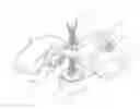
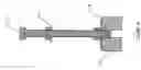
FIG. 1 is a perspective view of the assembly for the chain tensioning device for all terrain vehicles, or the like,
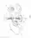
FIG. 2 shows an exploded view of the assembly depicted in FIG. 1,
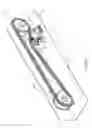
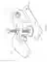
FIG. 3 shows the assembly of the chain tensioning device in its environment;
FIG. 4 is a cross-sectional view taken along line X-X; and
FIG. 5 is a further embodiment of the chain tensioning device where the longitudinal length of the T-bracket base has been extended.
THE DESCRIPTION OF THE PREFERRED EMBODIMENT
The accompanying drawings, as described above, illustrate a preferred embodiment of an assembly for a chain tensioning device. The following disclosure, describes a preferred embodiment of a chain tensioning device comprises the following assembly of component parts. Reference from FIG. 1 and FIG. 2 a chain tensioning device assembly 21, a T shaped base bracket 1, supports a freely pivoted arm 2 which is fastened by means of a bolt 9 and a nut 10 near and on one side of one end of the arm 2. At the opposite side and end of the arm 2, is an arched toggle slider, 3 made of urethane or of similar material fastened by means of a bolt 11, washers 12 and 13 and nut 16; said arched toggle slider 3 is free to pivot thus conforming with the chain loop. Located adjacent bolt 11 and nut 16 and opposite the arched toggle slider 3 is a vertical adjustable tap-bolt 5 threaded through a nut 6 a connector nut 15 welded to the arm 2, a nut 7, a washer 8 and a compressible rubber bushing foot 4 which is threaded part way through on the end of the adjustable tap-bolt 5 (shown in FIG. 4).
Reference from FIG. 3 the assembly of chain tensioning device 21 is shown in a functional environment. Located at either end of a chain loop 20 are two drive sprockets 22 and 24 between said drive sprockets and on the outer most often unloaded side of the chain loop is the chain tensioning device 21, enabling easy installation and access. The T shaped base bracket 1 is mounted to a flat supporting structure 26. The pivoted arm 2 extends angularly upward where the arched toggle slider 3 lifts the chain loop 20 to form an irregular compressed loop which creates tension on the chain between the two drive sprockets 22 and 24. The vertical adjustable tap-bolt 5 extends though the connector nut 15 welded to the arm 2 and part way through the compressible rubber bushing foot 4. The manual adjustment feature of the chain tensioning device is achieved by extending or retracting the threaded tap bolt 5 applying tension on the chain loop 20 and the pressure on the compressed rubber bushing foot 4. The required adjustments are infrequent in that the chain tensioming device smoothly cushions reversing loads, by the pivoting toggle action of the arched toggle slider 3 in concert with the adjustable feature of the arm 2 vertical tap bolt 5 and the compressible rubber bushing foot 4: all of which exerts a steady, even, modest pre-load tension pressure, when the chain loop 20 is under either a forward or reversed load. A further embodiment of this invention is shown in FIG. 5 wherein the base of bracket 1 extends the full longitudinal length of the arm 2. This chain tensioning assembly represents a simple compact, light weight, durable, quiet in operation and economical device and enables easy installation and access.
Claims
I claim:1. An assembly of a chain tensioning device for all terrain vehicle or the like comprising an assembly of a T shaped base bracket which supports a freely pivoted arm pivotally fastened on one side of one end of the arm, opposite side and end of the pivoted arm is freely pivoted arched toggle slider pivotally fastened to the pivoted arm and adjacent and opposite the arched toggle slider, is a vertical adjustable tap-bolt connecting the pivoted arm and supported by a compressible rubber bushing foot.
2. An assembly as described in claim 1 wherein the chain tensioning device is mounted on a supporting structure and is located below a chain looped and a pair of drive sprockets: the said chain tensioning device is located between the drive sprockets and on the outer most often unloaded side of the chain loop, the angularly upwardly extending pivot arm, lifts the arched toggle slider to form an irregular tensioned chain loop, a manual adjustment to the vertical tap-bolt exerts a desired steady, even modest pre-load tension pressure and reversing chain loads further progressively compress the rubber bushing foot as required.
3. An assembly as described in claims 1 and 2 wherein the base of bracket of the chain tensioning device extends the full longitudinal length of the device.
4. An assembly as described in claims 1, 2 and 3 wherein the chain tension devise has an adjustment bolt which provides a maximum range of adjustment while extending minimally above and below the chain.
Images & Drawings included:
Sources:
- United States Patent and Trademark Office - verify current appl. status at the USPTO↗
Similar patent applications:
- » 20170037956
Oil jet arm and method for lubricating chain span employing said oil jet arm, and chain tensioning device and method for lubricating chain span employing said chain tensioning device - » 20060247080
Chain tensioning device linking two strands of a chain drive - » 20090289496
Chain tensioning device - » 20120052996
Chain tensioner device - » 12386201
Side-mountable chain-tensioning device for a load-compensating trailer hitch - » 20090258737
Chain tensioner device - » 20110294612
Chain guide and chain tensioner device - » 20070219029
Fluid dampening chain tensioning device - » 17842353
Free hanging safety bead chain tension device - » 20120135832
Chain tensioner device
Recent applications in this class:
- » 20250243925 2025-07-31
TENSIONER SYSTEM FOR FLEXIBLE DRIVE MEMBER - » 20250180099 2025-06-05
BELT TENSION ADJUSTMENT SYSTEM - » 20240328485 2024-10-03
Spring structure for mechanical oil pump - » 20240328484 2024-10-03
Dynamic belt tension inference method and related motor driven roller system - » 20240229902 2024-07-11
TENSIONER - » 20240191782 2024-06-13
Tensioner - » 20240183432 2024-06-06
TRANSMISSION BELT ARRANGEMENT - » 20240167542 2024-05-23
Chain tensioner - » 20240133450 2024-04-25
Tensioner - » 20230383818 2023-11-30
SYSTEM FOR SUPPORTING AND TENSIONING CHAINS, BELTS AND THE LIKE