Cushion structure for bicycle
US20110241389A1
2011-10-06
12/753,546
2010-04-02
✅ Patent granted
US 8,167,369 B2
2012-05-01
-
-
Rodney B White
2030-08-21
Abstract:
A cushion structure for a bicycle contains a body and a bottom tube, wherein the body includes a circular inserting seat, the inserting seat includes a plurality of crossed support ribs extending radially from a center thereof and connecting with an outer rim thereof and formed in a cross shape, the bottom tube includes a connecting portion disposed on one end thereof, and the connecting portion includes a circularly inner hole corresponding to the inserting seat, and includes a plurality of retaining slots formed therein corresponding to the support ribs.
Assignee:
- Foming Bicycle Parts Co., Ltd. 1 🇹🇼 Changhwa Hsien, Taiwan
Interested in similar patents?
Get notified when new applications in this technology area are published.
Classification:
Y10T403/7016 » CPC further
Joints and connections; Interfitted members Diametric end slot is joint component
Y10T403/7045 » CPC further
Joints and connections; Interfitted members Interdigitated ends
B62J1/00 IPC
Saddles or other seats for cycles; Arrangement thereof; Component parts
B60N2/40 IPC
Seats specially adapted for vehicles; Arrangement or mounting of seats in vehicles for particular purposes or particular vehicles specially constructed for use on tractors or like off-road vehicles saddle type
B62J1/08 » CPC main
Saddles or other seats for cycles; Arrangement thereof; Component parts Frames for saddles; Connections between saddle frames and seat pillars; Seat pillars
F16D1/00 IPC
Couplings for rigidly connecting two coaxial shafts or other movable machine elements
F16D1/00 IPC
Couplings for transmitting mechanical rotation
F16D1/04 IPC
Couplings for rigidly connecting two coaxial shafts or other movable machine elements for connecting two abutting shafts or the like with clamping hub; with hub and longitudinal key
F16D1/068 IPC
Couplings for rigidly connecting two coaxial shafts or other movable machine elements for attachment of a member on a shaft or on a shaft-end non-disconnectable involving gluing, welding or the like
F16D1/10 IPC
Couplings for rigidly connecting two coaxial shafts or other movable machine elements Quick-acting couplings in which the parts are connected by simply bringing them together axially
Description
BACKGROUND OF THE INVENTION
1. Field of the Invention
The present invention relates to a structure of a bicycle, and more particularly to a cushion structure for a bicycle assembled by a bottom tube and a body directly.
2. Description of the Prior Art
Riding bicycles is a popular sport in recent years when people enjoy their leisure time to obtain exercise and environmental friendly purposes.
Conventional cushion of a bicycle includes a body and a support rod disposed on a bottom surface of the body, a locking member, and a seat post connected with the locking member and fixed to a frame of the bicycle. However, such a cushion is comprised of complicated components, heavy, and assembled time consumingly to increase production cost.
Therefore, an improved cushion of a bicycle has been developed and includes a body 3 as shown in FIG. 7, the body 3 includes a plurality of support ribs 31 and an integrally formed bottom tube 32 all of which are fixed on the bottom surface thereof.
However, such an improved cushion still has the following disadvantages:
1. The bottom tube 32 is integrally formed on the bottom surface of the body 3 that causes weak strength, and it is inserted to a seat post of the frame to generate a weaker support capability, therefore when a rider sits on the cushion, the bottom tube deforms easily to lower safety and comfort.
2. The bottom tube 32 is integrally formed on the bottom surface of the body 3, so bottom tubes with different lengths can not be replaced based on requirement.
The present invention has arisen to mitigate and/or obviate the afore-described disadvantages.
SUMMARY OF THE INVENTION
The primary object of the present invention is to provide a cushion structure for a bicycle that the body includes the inserting seat secured on the bottom surface thereof to fit the connecting portion of the bottom tube, and the bottom tube is made of metal material, hence the bottom tube is inserted to the seat post of the frame so as to enhance reinforcement and prevent the bottom tube from deformation when a rider sits on a seat, thus riding bicycle safely and comfortably.
Another object of the present invention is to provide a cushion structure for a bicycle that the body includes the inserting seat disposed on the bottom surface thereof to insert the connecting portion of the bottom tube, accordingly the bottom tubes with different lengths are replaced freely based on requirement.
To obtain the above objectives, a cushion structure for a bicycle provided by the present invention comprises a body and a bottom tube, wherein
the body includes a circular inserting seat, the inserting seat includes a plurality of crossed support ribs extending radially from a center thereof and connecting with an outer rim thereof and formed in a cross shape, the bottom tube includes a connecting portion disposed on one end thereof, and the connecting portion includes a circularly inner hole corresponding to the inserting seat, and includes a plurality of retaining slots formed therein corresponding to the support ribs.
BRIEF DESCRIPTION OF THE DRAWINGS
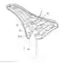
FIG. 1 is a perspective view showing the exploded components of a cushion structure for a bicycle according to a preferred embodiment of the present invention;
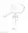
FIG. 2 is another perspective view showing the exploded components of the cushion structure for the bicycle according to the preferred embodiment of the present invention;
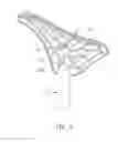
FIG. 3 is a perspective view showing the assembly of the cushion structure for the bicycle according to the preferred embodiment of the present invention;
FIG. 4 is a cross sectional view showing a part of the assembly of the cushion structure for the bicycle according to the preferred embodiment of the present invention;
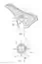
FIG. 5 is a perspective view showing the exploded components of a cushion structure for the bicycle according to another preferred embodiment of the present invention;
FIG. 6 is a cross sectional view showing a part of the assembly of the cushion structure for the bicycle according to the preferred embodiment of the present invention;
FIG. 7 is a perspective view of a conventional cushion structure for a bicycle.
DETAILED DESCRIPTION OF THE PREFERRED EMBODIMENTS
The present invention will be clearer from the following description when viewed together with the accompanying drawings, which show, for purpose of illustrations only, the preferred embodiment in accordance with the present invention.
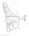
Referring to FIGS. 1-4, a cushion structure for a bicycle in accordance with a preferred embodiment of the present invention includes a body 1 and a bottom tube 2, wherein the body 1 includes a circular inserting seat 11, the inserting seat 11 includes a plurality of crossed support ribs 12 extending radially from a center thereof and connecting with an outer rim thereof and formed in a cross shape, the bottom tube 2 includes a connecting portion 21 disposed on one end thereof, and the connecting portion 21 includes a circularly inner hole 211 corresponding to the inserting seat 11, and includes a plurality of retaining slots 212 formed therein corresponding to the support ribs 12.
In assembly, the connecting portion 21 of the bottom tube 2 is applied glue, and the bottom tube 2 is inserted to the inserting seat 11 by using the inner hole 211 so that the retaining slots 212 of the connecting portion 21 engage with the support ribs 12 of the inserting seat 11 securely and tightly. In operation, the body 1 is covered by a shock-absorbing layer and an outer layer, and the bottom tube 2 is inserted to a seat post of a frame to be sat by a rider.
Referring to FIGS. 5 and 6, a cushion structure for a bicycle in accordance with another preferred embodiment of the present invention comprises a body 1 and a bottom tube 2, wherein the body 1 includes a circular inserting seat 11 fixed on a center of a bottom surface thereof, the inserting seat 11 includes a plurality of crossed support ribs 12 extending radially from a center thereof and connecting with an outer rim thereof, and includes a fitting member 13 proximate to the outer rim thereof, the bottom tube 2 includes a connecting portion 21 disposed on one end thereof, and the connecting portion 21 includes a circularly inner hole 211 corresponding to the inserting seat 11, and includes a plurality of retaining slots 212 formed therein corresponding to the support ribs 12.
In assembly, the connecting portion 21 of the bottom tube 2 is applied glue, and the bottom tube 2 is inserted to the inserting seat 11 of the body 1 by using the inner hole 211 so that the retaining slots 212 of the connecting portion 21 engage with the support ribs 12 of the inserting seat 11, and the fitting member 13 is fitted to an outer side of the connecting portion 21 securely and tightly. In operation, the body 1 is covered by a shock-absorbing layer and an outer layer, and the bottom tube 2 is inserted to a seat post of a frame to be sat by a rider.
Furthermore, the inserting seat 11 of the body 1 is formed in a cross or geometric shape, and the connecting portion 21 of the bottom tube 2 includes the inner hole 211 corresponding to the inserting seat 11.
The support ribs 12 of the body 1 can be also formed in an I shape, horizontal I shape, or radiation shape.
The bottom tube 2 can be also connected with the inserting seat 11 of the body 1 in a locking manner or by using a bolt and a bore to insert the bolt.
Thereby, the cushion structure of the present invention has the following advantages:
1. The body 1 includes the inserting seat 11 secured on the bottom surface thereof to fit the connecting portion 21 of the bottom tube 2, and the bottom tube 2 is made of metal material, hence the bottom tube 2 is inserted to the seat post of the frame so as to enhance reinforcement and prevent the bottom tube from deformation when a rider sits on a seat, thus riding bicycle safely and comfortably.
2. The body 1 includes the inserting seat 11 disposed on the bottom surface thereof to insert the connecting portion 21 of the bottom tube 2, accordingly the bottom tubes 2 with different lengths are replaced freely based on requirement.
While we have shown and described various embodiments in accordance with the present invention, it is clear to those skilled in the art that further embodiments may be made without departing from the scope of the present invention.
Claims
What is claimed:1. A cushion structure for a bicycle comprising;
a body including an inserting seat fixed on a center of a bottom surface thereof, a bottom tube including a connecting portion disposed on one end thereof, and the connecting portion including an inner hole corresponding to the inserting seat so as to be inserted to the inserting seat of the body.
2. The cushion structure for the bicycle as claimed in claim 1, wherein the inserting seat of the body is formed in a circular tube shape.
3. The cushion structure for the bicycle as claimed in claim 1, wherein the inserting seat of the body is formed in a cross shape.
4. The cushion structure for the bicycle as claimed in claim 1, wherein the inserting seat of the body includes a plurality of support ribs extending radially from a center thereof and connecting with an outer rim thereof.
5. The cushion structure for the bicycle as claimed in claim 4, wherein the support ribs are formed in a cross shape.
6. The cushion structure for the bicycle as claimed in claim 4, wherein the support ribs are formed in an inverted I shape.
7. The cushion structure for the bicycle as claimed in claim 4, wherein the support ribs are formed in a radiation shape.
8. The cushion structure for the bicycle as claimed in claim 1, wherein the inserting seat of the body includes a fitting member proximate to the outer rim thereof to be fitted to the connecting portion of the bottom tube.
9. The cushion structure for the bicycle as claimed in claim 1, wherein the bottom tube is applied glue and connected with the inserting seat of the body.
10. The cushion structure for the bicycle as claimed in claim 1, wherein the bottom tube is connected with the inserting seat of the body in a locking manner.
11. The cushion structure for the bicycle as claimed in claim 1, wherein the bottom tube is connected with the inserting seat of the body by using a bolt and a bore to insert the bolt.
Images & Drawings included:

Sources:
- United States Patent and Trademark Office - verify current appl. status at the USPTO↗
Similar patent applications:
- » 20110241390
Angle Adjusting Cushion Structure for Bicycle
Recent applications in this class:
- » 20250289525 2025-09-18
SHOCK-ABSORBING SEAT POST STRUCTURE - » 20250276751 2025-09-04
VEHICLE SEAT ADJUSTMENT AND SECURING SYSTEMS AND METHODS - » 20250263144 2025-08-21
ADJUSTABLE SEATPOST ARRANGEMENT FOR A BICYCLE - » 20250256796 2025-08-14
INFINITE ADJUST SEAT POST WITH PRESSURE RELIEF VALVE - » 20250214669 2025-07-03
DROPPER SEATPOST CAPABLE OF ADJUSTING MAXIMUM UPWARD STROKE - » 20250187688 2025-06-12
Bicycle saddle - » 20250187687 2025-06-12
HEIGHT ADJUSTABLE SEAT POSTS FOR BICYCLES AND SPACERS FOR HEIGHT ADJUSTABLE SEAT POSTS - » 20250171097 2025-05-29
BICYCLE SEAT TUBE CAPABLE OF ENHANCING STRUCTURAL STRENGTH - » 20250162673 2025-05-22
ADJUSTABLE SEATPOST ASSEMBLY - » 20250162672 2025-05-22
ADJUSTABLE HEIGHT OR DROPPER SEATPOST