Method for manufacturing a rectifier
US20110243752A1
2011-10-06
13/075,801
2011-03-30
✅ Patent granted
US 8,807,933 B2
2014-08-19
-
-
Edward Look | Christopher J Hargitt
Reinhart Boerner Van Deuren P.C.
2033-03-08
Abstract:
The present invention relates to a method for manufacturing a turbine-engine composite rectifier comprising a ferrule provided with a plurality of stator vanes (2), said stator vanes each comprising a blade (4) and optionally a platform (3), said method comprising at least the following steps:
-
- a) first layers of a reinforcement (6) are wound on a mandrel, said mandrel also acting as a mold and comprising protruding portions, said first reinforcement layers (6) comprising buttonholes (7) positioned facing the protruding portions;
- b) a prefabricated disc (9) is positioned on each of the protruding portions:
- c) last reinforcement layers (8) are wound above the discs (9), thereby forming a preform;
- d) a resin is injected into the closed mold with the preform and the resin-impregnated preform is polymerized;
- e) the polymerized preform is taken out of the mold and the base of the blade (4) or optionally the platform of the vane (3), if the latter comprises one of them, is added by welding on each of the discs (9).
Assignee:
- Techspace Aero S.A. 25 🇧🇪 Milmort, Belgium
Applicant:
Interested in similar patents?
Get notified when new applications in this technology area are published.
Classification:
B29C70/32 » CPC further
Shaping composites, i.e. plastics material comprising reinforcements, fillers or preformed parts, e.g. inserts comprising reinforcements only, e.g. self-reinforcing plastics; Shaping operations therefor; Shaping by lay-up, i.e. applying fibres, tape or broadsheet on a mould, former or core; Shaping by spray-up, i.e. spraying of fibres on a mould, former or core on a rotating mould, former or core
B29C70/48 » CPC main
Shaping composites, i.e. plastics material comprising reinforcements, fillers or preformed parts, e.g. inserts comprising reinforcements only, e.g. self-reinforcing plastics; Shaping operations therefor; Shaping or impregnating by compression not applied for producing articles of definite length, i.e. discrete articles using matched moulds, e.g. for deforming sheet moulding compounds [SMC] or prepregs and impregnating the reinforcements in the closed mould, e.g. resin transfer moulding [RTM], e.g. by vacuum
B29C70/86 » CPC further
Shaping composites, i.e. plastics material comprising reinforcements, fillers or preformed parts, e.g. inserts by incorporating or moulding on preformed parts, e.g. inserts or layers, e.g. foam blocks Incorporated in coherent impregnated reinforcing layers, e.g. by winding
B29C53/587 » CPC further
Shaping by bending, folding, twisting, straightening or flattening; Apparatus therefor; Winding and joining, e.g. winding spirally helically for making tubular articles with particular features having a non-uniform wall-structure, e.g. with inserts, perforations, locally concentrated reinforcements
F05D2230/232 » CPC further
Manufacture essentially without removing material by permanently joining parts together by welding
Y10T29/49323 » CPC further
Metal working; Method of mechanical manufacture; Impeller making; Turbomachine making Assembling fluid flow directing devices, e.g., stators, diaphragms, nozzles
F01D5/14 IPC
Blades; Blade-carrying members ; Heating, heat-insulating, cooling or antivibration means on the blades or the members; Blades Form or construction
B29C53/56 IPC
Shaping by bending, folding, twisting, straightening or flattening; Apparatus therefor Winding and joining, e.g. winding spirally
B29C66/721 » CPC further
General aspects of processes or apparatus for joining preformed parts characterised by the composition, physical properties or the structure of the material of the parts to be joined; Joining with non-plastics material characterised by the structure of the material of the parts to be joined Fibre-reinforced materials
F01D9/044 » CPC further
Stators; Nozzles; Nozzle boxes; Stator blades; Guide conduits, e.g. individual nozzles forming ring or sector fixing blades to stators permanently, e.g. by welding, brazing, casting or the like
B29C66/73751 » CPC further
General aspects of processes or apparatus for joining preformed parts characterised by the composition, physical properties or the structure of the material of the parts to be joined; Joining with non-plastics material characterised by the intensive physical properties of the material of the parts to be joined, by the optical properties of the material of the parts to be joined, by the extensive physical properties of the parts to be joined, by the state of the material of the parts to be joined or by the material of the parts to be joined being a thermoplastic or a thermoset characterised by the state of the material of the parts to be joined uncured, partially cured or fully cured the to-be-joined area of at least one of the parts to be joined being uncured, i.e. non cross-linked, non vulcanized
B29C66/723 » CPC further
General aspects of processes or apparatus for joining preformed parts characterised by the composition, physical properties or the structure of the material of the parts to be joined; Joining with non-plastics material characterised by the structure of the material of the parts to be joined being multi-layered
B29C66/7392 » CPC further
General aspects of processes or apparatus for joining preformed parts characterised by the composition, physical properties or the structure of the material of the parts to be joined; Joining with non-plastics material characterised by the intensive physical properties of the material of the parts to be joined, by the optical properties of the material of the parts to be joined, by the extensive physical properties of the parts to be joined, by the state of the material of the parts to be joined or by the material of the parts to be joined being a thermoplastic or a thermoset characterised by the material of the parts to be joined being a thermoplastic or a thermoset characterised by the material of at least one of the parts being a thermoplastic
B29K2063/00 » CPC further
Use of epoxy resins , as moulding material
F05D2300/603 » CPC further
Materials; Properties thereof; Properties or characteristics given to material by treatment or manufacturing Composites; e.g. fibre-reinforced
B29C66/7394 » CPC further
General aspects of processes or apparatus for joining preformed parts characterised by the composition, physical properties or the structure of the material of the parts to be joined; Joining with non-plastics material characterised by the intensive physical properties of the material of the parts to be joined, by the optical properties of the material of the parts to be joined, by the extensive physical properties of the parts to be joined, by the state of the material of the parts to be joined or by the material of the parts to be joined being a thermoplastic or a thermoset characterised by the material of the parts to be joined being a thermoplastic or a thermoset characterised by the material of at least one of the parts being a thermoset
F05D2300/44 » CPC further
Materials; Properties thereof; Organic materials Resins
B29C70/865 » CPC further
Shaping composites, i.e. plastics material comprising reinforcements, fillers or preformed parts, e.g. inserts by incorporating or moulding on preformed parts, e.g. inserts or layers, e.g. foam blocks; Incorporated in coherent impregnated reinforcing layers, e.g. by winding completely encapsulated
B29C65/02 » CPC further
Joining of preformed parts ; Apparatus therefor by heating, with or without pressure
B29C66/474 » CPC further
General aspects of processes or apparatus for joining preformed parts; General aspects of joining substantially flat articles, e.g. plates, sheets or web-like materials; Making flat seams in tubular or hollow articles; Joining single elements to substantially flat surfaces; Joining single elements to sheets, plates or other substantially flat surfaces said single elements being substantially non-flat
F01D9/04 » CPC further
Stators; Nozzles; Nozzle boxes; Stator blades; Guide conduits, e.g. individual nozzles forming ring or sector
F05D2300/614 » CPC further
Materials; Properties thereof; Properties or characteristics given to material by treatment or manufacturing Fibres or filaments
F01D9/00 IPC
Stators
B29C53/58 IPC
Shaping by bending, folding, twisting, straightening or flattening; Apparatus therefor; Winding and joining, e.g. winding spirally helically
B29C65/00 IPC
Joining of preformed parts ; Apparatus therefor
Description
FIELD OF THE INVENTION
The present invention relates to a method for manufacturing a rectifier for a turbine engine.
It more particularly relates to a method for manufacturing composite inner or outer ferrules with integrated or added vanes.
It also relates to the rectifier obtained according to the method.
STATE OF THE ART
Axial compressors are well known per se and are used i.a. in turbine engines.
These low or high pressure compressors comprise several stages of rotating vanes that are separated by rectifier stages which have the purpose of repositioning the velocity vector of the fluid exiting the previous stage before sending it to the next stage.
These rectifier stages essentially comprise fixed vanes, further called stator vanes, connecting an outer ferrule to an inner ferrule, both being concentric and delimiting the airflow area or aerodynamic vein.
Stator vanes generally comprise a platform that is attached to the outer ferrule by riveting, welding, bolting, adhesive bonding, etc. Examples of assembling with rivets (U.S. Pat. No. 6,543,995 A) and bolts (EP 1 936 121 A) are illustrated in FIGS. 1a and 1b, respectively (cf. caption).
Assembling with rivets, bolts, etc. has the drawback of requiring that apertures be pierced in the ferrule in order to let through attachment elements, which causes a reduction in the structural strength of the ferrule.
Assembling by adhesive bonding has the disadvantage of not allowing its use as the only assembling method but always as an addition to another assembling method, for example with screws, and this in order to ensure better mechanical performance.
AIMS OF THE INVENTION
The present invention aims to provide a solution which allows to overcome the drawbacks of the state of the art.
The present invention aims in particular to produce an assembly between vanes and ferrules that does not weaken the mechanical strength of the ferrule.
The present invention further aims to produce an assembly between vanes and ferrules allowing the vanes to be easily repaired in the event of breakage.
SUMMARY OF THE INVENTION
The present invention relates to a method for manufacturing a composite rectifier for a turbine engine comprising a ferrule provided with a plurality of stator vanes, said stator vanes each comprising one blade and optionally one platform, said method comprising at least the following steps:
-
- a) first layers of a reinforcement are wound on a mandrel, said mandrel also acting as a mold and comprising protruding portions, said first reinforcement layers comprising buttonholes positioned facing the protruding portions;
- b) a prefabricated disc is positioned on each of the protruding portions;
- c) last reinforcement layers are wound above the discs, thereby forming a preform;
- d) a resin is injected into the closed mold with the preform and the resin-impregnated preform is polymerized;
- e) the polymerized preform is taken out of the mold and the base of the blade, or optionally the platform of the vane if the latter comprises one of them, is added by welding on each of the discs.
According to particular embodiments of the invention, the method comprises at least one or a suitable combination of the following features:
-
- the prefabricated disc and the vane are made in a thermoplastic material;
- the prefabricated disc and the vane are made in a metal material;
- the disc comprises protrusions and/or asperities, said protrusions and asperities ensuring the anchoring of the disc in the preform;
- the vane and the disc comprise a reinforcement with long, medium or short fibers;
- in step e), the vane is added to the disc by thermoplastic welding;
- the resin is a thermosetting resin;
- the resin is polymerized at a temperature below the melting temperature of the disc;
- the thermosetting resin is an epoxy resin;
- the thermoplastic disc is made in PEEK, PEKK or PEI;
- the reinforcement comprises braids, fabrics or non-woven fabrics (NCF: Non-Crimp Fabrics);
- the protruding portions comprise spikes;
- in the event of breakage or damage of a vane, a new vane is added to the disc by welding;
- the weld is positioned on the inner face of the ferrule or outside the inner face of the ferrule.
The present invention also relates to a turbine-engine rectifier obtained by means of the method as described above.
SHORT DESCRIPTION OF THE DRAWINGS
FIGS. 1a and 1b, already mentioned, respectively illustrate a three-dimensional view and a sectional view of assembly examples between stator vanes and outer ferrule as in the state of the art (cf. caption).
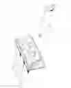
FIG. 2 illustrates a three-dimensional view of the stator vanes inserted between the reinforcement layers of the preform of the outer ferrule as in a first embodiment of the invention.
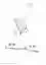
FIG. 3 illustrates a sectional view corresponding to the assembly of FIG. 2.
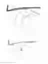
FIG. 4 illustrates a front view of a stator vane added to a disc inserted between the reinforcement layers of the preform of the outer ferrule as in a second embodiment of the invention.
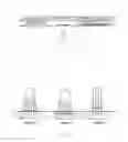
FIG. 5 illustrates a schematic view of three locations of the weld between the disc and the vane as in the second embodiment of the invention.
CAPTION
(1) Assembly flange between outer ferrules
(2) Stator vane
(3) Platform of the vane
(4) Blade of the vane
(5) Outer ferrule
(6) First layers of the reinforcement of the preform of the ferrule
(7) Buttonhole on the first layers of the reinforcement of the preform of the ferrule
(8) Last layers of the reinforcement of the preform of the ferrule
(9) Disc
(10) Protrusion of the disc
(11) Weld
DETAILED DESCRIPTION OF THE INVENTION
The present invention relates to a method for manufacturing a turbine-engine rectifier and, more particularly to a method for manufacturing a ferrule with integrated vanes as in a first embodiment of the invention or added vanes as in a second embodiment of the invention. The present invention is illustrated for the manufacturing of an outer ferrule but the method as in the invention also applies for manufacturing an inner ferrule.
According to the first embodiment illustrated in FIGS. 2 and 3, the method comprises at least five steps. A first step a) consists in winding the first layers 6 of a reinforcement on a mandrel (not shown) also acting as a mold and comprising openwork. The first reinforcement layers 6 comprise buttonholes 7 positioned facing the openwork. In a second step b), the vanes 2, and more particularly the blades 4 of the vanes are inserted through the buttonholes 7 of the first layers 6 and the openwork of the mandrel in the direction of the arrow shown in FIG. 3. Preferentially, the vane 2 comprises a platform 3 with protrusions (not shown) used as mechanical anchoring. The surface of the platform may also comprise asperities (not shown) always with the goal of improving its anchoring. In a third step c), the last reinforcement layers 8 are wound above the vane platforms 3 in order to complete the preform of the rectifier. In a fourth step d), the mold is closed, a resin is injected around the vane platforms and the impregnated preform is polymerized. A fifth and last step e) consists in opening the mold and in removing from the mold the rectifier thereby obtained.
According to the second embodiment illustrated in FIG. 4, the method comprises at least 5 steps. A first step a) consists in winding the first layers of a reinforcement 6 on a mandrel (not shown) also acting as a mold and comprising no openwork but protruding portions, such as for example, spikes, radially positioned at the future location of the vanes. The first reinforcement layers 6 comprise buttonholes 7 positioned facing the protruding portions. In a second step b), prefabricated discs 9 are positioned on the protruding portions. There are as many discs as there are vanes to be attached to the ferrule. According to the present invention, the disc 9 comprises protrusions 10, i.e. extensions of the disc in axial and circumferential directions, these protrusions 10 lie on the first reinforcement layers 6. Alternatively, the disc comprises asperities (not shown) on its surface. According to still another alternative, the disc comprises protrusions as well as asperities on its surface. In a third step c), the last reinforcement layers 8 are wound above the discs 9 and their protrusions 10. In a fourth step d), the mold is closed, a resin is injected around the discs and the impregnated preform is polymerized. A fifth step e) consists in opening the mold and in adding by welding (11: weld) the vanes 2 onto the discs 9. The platform of the vane, if the latter comprises one of them, or the base of the vane blade, if the vane does not comprise any platform, is welded or consolidated together on the disc. The welding between the disc 9 and the vane 2 may be achieved in different positions as illustrated in FIG. 5. The weld 11 is advantageously positioned in position 2 or 3, i.e. outside the most mechanically-stressed area, namely the inner face of the ferrule (face in the aerodynamic vein).
According to both aforementioned embodiments of the invention, the injected resin is preferentially a thermosetting resin, for example an epoxy resin, appearing in the liquid form and reaching out to the contours and asperities of the platform or of the disc, thereby allowing proper anchoring of the latter. The polymerization of the resin is achieved at a temperature below the melting temperature of the vane or of the disc in order to avoid softening of the latter. The vanes as well as the discs may be made in a thermoplastic or metal material. The vanes and the discs are preferentially made in a thermoplastic material, and in the second embodiment, the vanes are added to the discs by thermoplastic welding. As an example, the vane and the disc are made in a PEEK (polyetheretherketone) resin, a PEKK (polyetheretherketoneketone) resin or PEI (polyetherimide) resin. The reinforcement of the ferrule may be braids, fabrics or non-woven fabrics (so-called NCF for Non-Crimp Fabrics). Similarly, the vane and the thermoplastic disc also comprise a reinforcement that may be with long, medium or short fibers.
ADVANTAGES OF THE METHOD AS IN THE INVENTION
The assembling is simplified since it is not necessary to have attachment elements such as rivets, bolts, etc.
The connection between the vane (or the disc) and the ferrule is achieved in one single operation that is common with the manufacturing of the ferrule, which allows to increase the integration at the manufacturing level.
The method as in the invention allows to manufacture ferrules and vanes in composite material. The manufacturing of composite vanes and outer ferrules thereby generates a gain in mass by about 13% relative to a welded assembly between outer ferrules and vanes respectively made in titanium.
According to the second embodiment of the invention, in the event of breakage of a vane, a new vane may be easily added to the disc by thermoplastic welding.
Locating the weld in positions 2 and 3 as in the second embodiment allows to ensure the continuity of the fibers of the vane (position 2) or of the disc (position 3) in the most mechanically-stressed area.
Claims
1. A method for manufacturing a turbine-engine composite rectifier comprising a ferrule provided with a plurality of stator vanes (2), said stator vanes each comprising a blade (4) and optionally a platform (3), said method comprising at least the following steps:
a) first layers of a reinforcement (6) are wound on a mandrel, said mandrel also acting as a mold and comprising protruding portions, said first reinforcement layers (6) comprising buttonholes (7) positioned facing the protruding portions;
b) a prefabricated disc (9) is positioned on each of the protruding portions;
c) last reinforcement layers (8) are wound above the discs (9), thereby forming a preform;
d) a resin is injected into the closed mold with the preform and the resin-impregnated preform is polymerized;
e) the polymerized preform is taken out of the mold and the base of the blade (4) or optionally the platform of the vane (3), if the latter comprises one of them, is added by welding on each of the discs (9).
2. The method as in claim 1, wherein the prefabricated disc (9) and the vane (2) are made in a thermoplastic material.
3. The method as in claim 1, wherein the prefabricated disc (9) and the vane (2) are made in a metal material.
4. The method as in claim 1, wherein the disc (9) comprises protrusions (10) and/or asperities, said protrusions and asperities ensuring the anchoring of the disc in the preform.
5. The method as in claim 2, wherein the vane (2) and the disc (9) comprise a reinforcement with long, medium or short fibers.
6. The method as in claim 2, wherein, in step e), the vane (2) is added to the disc (9) by thermoplastic welding.
7. The method as in claim 1, wherein the resin is a thermosetting resin.
8. The method as in claim 7, wherein the resin is polymerized at a temperature below the melting temperature of the disc (9).
9. The method as in claim 7, wherein the thermosetting resin is an epoxy resin.
10. The method as in claim 2, wherein the thermoplastic disc (9) is made in PEEK, PEKK or PEI.
11. The method as in claim 1, wherein the reinforcement (6,8) comprises braids, fabrics or non-woven fabrics (NCF: Non-Crimp Fabrics).
12. The method as in claim 1, wherein the protruding portions comprise spikes.
13. The method as in claim 1, wherein, in the event of breakage or damage of a vane (2), a new vane (2) is added to the disc (9) by welding.
14. The method as in claim 1, wherein the weld (11) is positioned on the inner face of the ferrule or outside the inner face of the ferrule.
15. A turbine-engine rectifier obtained by means of the method as in claim 1.
Images & Drawings included:
Sources:
- United States Patent and Trademark Office - verify current appl. status at the USPTO↗
Similar patent applications:
- » 20080053952
Rectifying Device, Electronic Circuit Using the Same, and Method of Manufacturing Rectifying Device - » 20140225058
RECTIFYING DEVICE, ELECTRONIC CIRCUIT USING THE SAME, AND METHOD OF MANUFACTURING RECTIFYING DEVICE - » 20190036460
Method for manufacturing rectifier and rectifier - » 20110079819
IGBT with fast reverse recovery time rectifier and manufacturing method thereof - » 20150162846
Method for manufacturing rectifier and rectifier - » 18614439
Semiconductor rectifier and manufacturing method of the same - » 20170352722
Semiconductor rectifier and manufacturing method thereof - » 20150050791
Method for manufacturing rectifier with vertical MOS structure - » 20060278889
Power rectifier and manufacturing method thereof - » 20200243507
Silicon controlled rectifier and manufacturing method therefor
Recent applications in this class:
- » 20250289193 2025-09-18
RESIN TRANSFER MOLDING IN COMPOSITE MANUFACTURING - » 20250256472 2025-08-14
DRAINAGE MEMBRANE FOR THE MANUFACTURE OF COMPOSITE MATERIALS - » 20250242557 2025-07-31
COMPOSITE STRUCTURE FOR A TURBINE ENGINE - » 20250144895 2025-05-08
Compression Resin Transfer Infusion Methods - » 20250065577 2025-02-27
METHOD FOR PRODUCING A PART, IN PARTICULAR A PART MADE FROM A COMPOSITE MATERIAL - » 20250033300 2025-01-30
METHOD AND TOOL SYSTEM FOR MANUFACTURING A COMPONENT FROM A FIBER-REINFORCED PLASTIC - » 20250026091 2025-01-23
METHOD FOR MANUFACTURING A BLADE, IN PARTICULAR A COMPOSITE BLADE - » 20250018664 2025-01-16
VACUUM INFUSION SYSTEM AND METHOD FOR VACUUM INFUSING A FIBRE REINFORCEMENT WITH A RESIN - » 20250018663 2025-01-16
CURING TOOL ASSEMBLIES, METHODS AND SYSTEMS FOR COMPOSITE MANUFACTURING - » 20250010558 2025-01-09
SYSTEM AND METHOD FOR RESIN TRANSFER MOULDING
Recent applications for this Assignee:
- » 20140345247 2014-11-27
Tank and method for manufacturing same - » 20130142988 2013-06-06
Method for making a preform - » 20120171044 2012-07-05
Composite-material vane - » 20120168115 2012-07-05
INTEGRATION OF A SURFACE HEAT-EXCHANGER WITH REGULATED AIR FLOW IN AN AIRPLANE ENGINE - » 20120134787 2012-05-31
Abradable for stator inner shroud - » 20120130617 2012-05-24
Method for monitoring the oil system of a turbomachine - » 20120128466 2012-05-24
ADVANCED AIR AND OIL CIRCUIT ARCHITECTURE FOR TURBOMACHINE - » 20110318185 2011-12-29
Lightened axial compressor rotor - » 20110318174 2011-12-29
Compressor rectifier architecture - » 20110150643 2011-06-23
Architecture of a compressor rectifier