Screen device and downhole screen
US20110247801A1
2011-10-13
12/758,414
2010-04-12
✅ Patent granted
US 9,387,420 B2
2016-07-12
-
-
Brad Harcourt
Cantor Colburn, LLP
2031-09-19
Abstract:
A screen device includes a foam body having a passageway that extends longitudinally through the foam body, the foam body has an open cell structure such that at least two surfaces of the foam body are in fluidic communication with one another through the foam body.
Inventors:
- Edward J. O'Malley 65 🇺🇸 Houston, TX, United States
- Brad G. Baker 1 🇺🇸 Houston, TX, United States
Assignee:
- BAKER HUGHES INCORPORATED 5,929 🇺🇸 Houston, TX, United States
Applicant:
Interested in similar patents?
Get notified when new applications in this technology area are published.
Classification:
E03B3/18 IPC
Methods or installations for obtaining or collecting drinking water or tap water from underground; Obtaining and confining water by means of wells; Component parts of wells Well filters
B01D35/28 IPC
Other filtering devices; Auxiliary devices for filtration; Filter housing constructions Strainers not provided for elsewhere
E21B47/01 » CPC further
Survey of boreholes or wells Devices for supporting measuring instruments on drill bits, pipes, rods or wirelines; Protecting measuring instruments in boreholes against heat, shock, pressure or the like
E21B17/1035 » CPC further
Drilling rods or pipes; Flexible drill strings; Kellies; Drill collars; Sucker rods; Casings Cables; ; Tubings; Wear protectors; Centralising devices, e.g. stabilisers for plural rods, pipes or lines, e.g. for control lines
E21B43/082 » CPC further
Methods or apparatus for obtaining oil, gas, water, soluble or meltable materials or a slurry of minerals from wells; Subsoil filtering; Screens or liners Screens comprising porous materials, e.g. prepacked screens
B01D2201/06 » CPC further
Details relating to filtering apparatus Resilient foam as filtering element
B01D29/15 » CPC main
Other filters with filtering elements stationary during filtration, e.g. pressure or suction filters, or filtering elements therefor with bag, cage, hose, tube, sleeve or like filtering elements; Supported filter elements arranged for inward flow filtration
E21B43/08 IPC
Methods or apparatus for obtaining oil, gas, water, soluble or meltable materials or a slurry of minerals from wells; Subsoil filtering Screens or liners
E21B17/10 IPC
Drilling rods or pipes; Flexible drill strings; Kellies; Drill collars; Sucker rods; Casings Cables; ; Tubings Wear protectors; Centralising devices, e.g. stabilisers
Description
BACKGROUND
Screens are commonly used in tubular systems to separate particulate from fluids. Such systems are employed in the downhole completion industry to separate sand and other particulate from hydrocarbons such as oil, water and natural gas, for example. Communication across these screens can be difficult depending upon the construction of the screen itself. Screen devices that simplify communication thereacross are welcomed in the art.
BRIEF DESCRIPTION
Disclosed herein is a screen device that includes a foam body having a passageway that extends longitudinally through the foam body. The foam body has an open cell structure such that at least two surfaces of the foam body are in fluidic communication with one another through the foam body.
Further disclosed is a downhole screen including a tubular having a wall with perforations therethrough and a foam body, having an open cell structure, surroundingly disposed at the tubular. The open cell structure provides fluidic communication between an outer surface of the foam body and an inside of the tubular. The foam body also has a conduit extending longitudinally therethrough.
BRIEF DESCRIPTION OF THE DRAWINGS
The following descriptions should not be considered limiting in any way. With reference to the accompanying drawings, like elements are numbered alike:
FIG. 1 depicts a cross-sectional view of a screen device disclosed herein;
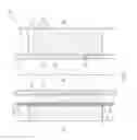
FIG. 2 depicts a side view of the a screen device disclosed herein with a helical conduit;
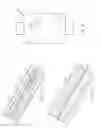
FIG. 3 depicts a partial cross-sectional view of a conduit shown in FIG. 2 with a line running therethrough; and
FIG. 4 depicts a partial cross-sectional view of an alternate conduit with a line running therethrough.
DETAILED DESCRIPTION
A detailed description of one or more embodiments of the disclosed apparatus and method are presented herein by way of exemplification and not limitation with reference to the Figures.
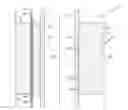
Referring to FIG. 1, an embodiment of a screen device disclosed herein is shown generally at 10. The screen device 10 is shown within a wellbore 11 of an earth formation 12. The screen device 10 has a foam, which in one iteration is an open cell foam, body 13 that surrounds a tubular 14 positioned within a void 18 that extends longitudinally through the screen device 10. Additionally, a line 22 is shown positioned within a conduit 26 of the screen device 10, also referred to herein as a passageway, that extends longitudinally through the screen device 10. In this embodiment an axis 27A of the void 18 is substantially parallel to an axis 27B of the conduit 26. Both the void 18 and the conduit 26 have perimetrically continuous walls 28A, 28B, which may be either permeable or non-permeable to fluid. The foam body 13 is an open cell structured foam 31 to allow fluid to flow therethrough from an outside 29 of the screen device 10, defined by outer surface 30, to the void 18 for embodiments wherein the walls 28A are permeable. In this embodiment the open cell structured foam 31 provides filtering of fluid passing therethrough. Perforations 34 in the tubular 14 allow fluid passing through the screen device 10 to flow to an inside 38 of the void 18. Once the fluid is on the inside 38 it can flow longitudinally through the tubular 14 in either direction. Fluid initially on the inside 38 can also flow out through the perforations 34, through the open cell structured foam 31 and to the outside 29.
The conduit 26 provides an unobstructed passageway from a first end 42 of the screen device 10 to a second end 46 of the screen device 10. As mentioned above, the walls 28B of the conduit 26 may be permeable so that fluid is able to pass therethrough in either direction between the open cell structured foam 31 and the conduit 26. An embodiment wherein the walls 28B are permeable permits treatments therethrough. For example, chemical injection for treating the open cell structured foam 31 or the earth formation 12, such as for acid treatments or corrosion inhibitor treatments.
The anticipated treatments and environmental conditions in which the screen device 10 will be operational will influence materials used to construct the foam body 13. Additional considerations include whether or not the foam body 13 needs to be deformable or not. As such, materials contemplated for the foam body 13 include resins, polyolefins, polyurethanes, polyvinylchlorides, metals, ceramics and combinations thereof.
Regardless of the material of the foam body 13, running the line 22 through the conduit 26 provides a means of communicating through the screen device 10. The line 22 can be one or more of several lines commonly used in downhole completion applications, such as, a hydraulic line, an electric line, a fiber optic cable and a chemical injection line, for example.
Referring to FIG. 2, the line 22 can be free to slide within the conduit 26 by sizing the line 22 and the conduit 26 with an annular space 54 therebetween. Alternately, the line 22 can be fixedly attached to the conduit 26, as illustrated in FIG. 3. One way to attach the line 22 to the conduit 26 is to surround the line 22 with a foam 58 that is radially small enough to be run into the conduit 26 prior to expansion of the foam 58 and subsequent adhesion to the walls 28B. The foam 58 can be compacted or fabricated to a smaller radial dimension prior to running through the conduit 26. The foam 58 can further be configured to expand radially in response to exposure to such things as temperature or chemical exposure, for example, that the foam 58 is anticipated to encounter once placed in application.
Referring to FIG. 4, attachment of the line 22 to the conduit 26 can be used to sense parameters of the screen device 10. For example, use of fiber optic cable as the line 22 permits measurement of stresses encountered by the screen device 10.
While the invention has been described with reference to an exemplary embodiment or embodiments, it will be understood by those skilled in the art that various changes may be made and equivalents may be substituted for elements thereof without departing from the scope of the invention. In addition, many modifications may be made to adapt a particular situation or material to the teachings of the invention without departing from the essential scope thereof. Therefore, it is intended that the invention not be limited to the particular embodiment disclosed as the best mode contemplated for carrying out this invention, but that the invention will include all embodiments falling within the scope of the claims. Also, in the drawings and the description, there have been disclosed exemplary embodiments of the invention and, although specific terms may have been employed, they are unless otherwise stated used in a generic and descriptive sense only and not for purposes of limitation, the scope of the invention therefore not being so limited. Moreover, the use of the terms first, second, etc. do not denote any order or importance, but rather the terms first, second, etc. are used to distinguish one element from another. Furthermore, the use of the terms a, an, etc. do not denote a limitation of quantity, but rather denote the presence of at least one of the referenced item.
Claims
What is claimed:1. A screen device comprising a foam body having a passageway that extends longitudinally through the foam body, the foam body having an open cell structure such that at least two surfaces of the foam body are in fluidic communication with one another through the foam body.
2. The screen device of claim 1, wherein one of the at least two surfaces defines a wall of a void in the foam body.
3. The screen device of claim 2, wherein the void is receptive to a perforated tubular.
4. The screen device of claim 2, wherein the passageway is helically spiraled about the void.
5. The screen device of claim 2, wherein the foam body surrounds the void and an inside of the void and an outside of the foam body are in fluidic communication through the open cell structure.
6. The screen device of claim 1, wherein a longitudinal axis of the passageway is substantially parallel to a longitudinal axis of the foam body.
7. The screen device of claim 1, wherein the passageway is sealed from the open cell structure.
8. The screen device of claim 1, wherein the foam body defines a tubular.
9. The screen device of claim 1, wherein the foam body is positioned on a downhole tool string and the passageway forms a conduit receptive to a line.
10. The screen device of claim 9, wherein the line is at least one of a hydraulic line, an electric line, a fiber optic cable and a chemical injection line.
11. The screen device of claim 1, wherein the passageway has a perimetrically continuous wall.
12. The screen device of claim 2, wherein the void has a perimetrically continuous wall.
13. A downhole screen, comprising:
a tubular having a wall with perforations therethrough; and
a foam body surroundingly disposed at the tubular having an open cell structure providing fluidic communication between an outer surface of the foam body and an inside of the tubular, the foam body further having a conduit extending longitudinally therethrough.
14. The downhole screen of claim 13, wherein the conduit helically surrounds the tubular.
15. The downhole screen of claim 13, wherein an axis of the conduit is substantially parallel with an axis of the foam body.
16. The downhole screen of claim 13, wherein the conduit is fluidically sealed from the foam body.
17. The downhole screen of claim 13, further comprising a line running through the conduit.
18. The downhole screen of claim 17, wherein the line is fixedly attached to the foam body.
19. The downhole screen of claim 17, wherein the line is slidably engaged with the foam body.
20. The downhole screen of claim 17, wherein the line is one of a hydraulic control line, an electric line, a fiber optic cable and a chemical injection line
21. The downhole screen of claim 13, wherein the foam body is constructed of resins, polyolefins, polyurethanes, polyvinylchlorides, metals, ceramics and combinations thereof.
Images & Drawings included:
Sources:
- United States Patent and Trademark Office - verify current appl. status at the USPTO↗
Similar patent applications:
Recent applications in this class:
- » 20250196028 2025-06-19
HEREWITH FILTER ELEMENT AND FILTER MODULE - » 20250186911 2025-06-12
FILTER CARTRIDGE WITH OFFSET OUTLET AND INTEGRATED BYPASS - » 20250073620 2025-03-06
Water Quality Purification Assembly and Refrigeration Device - » 20250058254 2025-02-20
FILTER ELEMENT - » 20250010223 2025-01-09
BACKFLUSH FILTER ASSEMBLY - » 20250001330 2025-01-02
APPARATUS FOR FILTERING AND CLEANING WATER IN A MIKVAH (JEWISH RITUAL PURIFICATION BATH), WHICH COMPLY WITH JEWISH RELIGIOUS LAWS (HALACHA), AND APPLICATIONS THEREOF - » 20240424430 2024-12-26
FILTER ASSEMBLY WITH MULTIPLE SEAL ELEMENT - » 20240408518 2024-12-12
SPIN-ON FILTER ASSEMBLY FOR EXISTING FILTER HEAD WITH REUSABLE HOUSING AND FILTER ELEMENT ADAPTOR AND DISPOSABLE CORELESS ELEMENT - » 20240269583 2024-08-15
FILTER ASSEMBLY WITH FILTER ELEMENT ENDCAP HAVING INTEGRAL EXTERNAL ROUNDED POLYGON SHAPED SEALING SURFACE - » 20240252959 2024-08-01
Collar having modular parts for supporting stratified filtration
Recent applications for this Assignee:
- » 20230011321 2023-01-12
Polycrystalline diamond - » 20220144646 2022-05-12
SUPERHARD CONSTRUCTIONS & METHODS OF MAKING SAME - » 20220049603 2022-02-17
SYNTHETIC FORMATION EVALUATION LOGS BASED ON DRILLING VIBRATIONS - » 20200224533 2020-07-16
Segmented wireless production logging - » 20200048977 2020-02-13
Subsea module and downhole tool - » 20190366442 2019-12-05
SUPERHARD CONSTRUCTIONS & METHODS OF MAKING SAME - » 20190338636 2019-11-07
Synthetic formation evaluation logs based on drilling vibrations - » 20190331466 2019-10-31
System and method for altering a burn rate of a propellant - » 20190257194 2019-08-22
Dual telemetric coiled tubing system - » 20190203541 2019-07-04
Polycrystalline diamond compacts and earth-boring tools including such compacts