Near zero inertia pendulum golf swing trainer Swinky™
US20110250982A1
2011-10-13
12/798,664
2010-04-09
Abstract:
Swinky™ is a pendulum golf swing trainer. It weighs about six pounds, folds up like an umbrella, and can be unfolded and set up without tools in a moment. It comprises a long, stiff, ultra-light pendulum arm that hangs atop a mast, planted on a sure-footed tripod opposite the golfer's chin. The golfer's club makes up at least 98% of the weight of the pendulum bob. The other vital 2% of the bob's weight is provided by the device's low-inertia, visually graphic rectangular string bridge, one end of which is anchored on the neck of the club shaft and the other on the tip of the pendulum arm. The club swings accompanied by the bridge quite unaffected by its presence as long as the club's center of mass tracks parallel to and centered with the sweep of the pendulum arm. Exploiting rectangle feedback is simple. Preset the mast angle to match the lie angle of the club shaft and the top of the mast to the height of the golfer's own chin at address. Start and complete swings with the bridge just sufficiently tensioned to form the rectangle. Proper swings are confirmed by steadiness of the mast and tripod throughout the swing, along with air speed whistling that peaks at the bottom of the swing. A faulty swing at any point instantly deforms the rectangle and rocks the mast and tripod.
Interested in similar patents?
Get notified when new applications in this technology area are published.
Classification:
A63B69/3676 » CPC main
Training appliances or apparatus for special sports for golf for putting
A63B69/36213 » CPC further
Training appliances or apparatus for special sports for golf; Contacting or non-contacting mechanical means for guiding the swing; Mechanical guides guiding the club head end during the complete swing, e.g. rails with arm or rod fixed on the club and rotating around a fixed supporting point
A63B69/0057 » CPC further
Training appliances or apparatus for special sports Means for physically limiting movements of body parts
A63B69/3621 » CPC further
Training appliances or apparatus for special sports for golf Contacting or non-contacting mechanical means for guiding the swing
A63B71/023 » CPC further
Games or sports accessories not covered in groups - for large-room or outdoor sporting games Supports, e.g. poles
A63B2209/023 » CPC further
Characteristics of used materials with reinforcing fibres, e.g. carbon, polyamide fibres Long, oriented fibres, e.g. wound filaments, woven fabrics, mats
A63B2210/50 » CPC further
Space saving Size reducing arrangements for stowing or transport
A63B2225/093 » CPC further
Miscellaneous features of sport apparatus, devices or equipment; Adjustable dimensions Height
A63B69/36 IPC
Training appliances or apparatus for special sports for golf
Description
BACKGROUND OF THE INVENTION
Prior art disclosed in the inventor's U.S. Pat. No. 5,474,299 golf swing trainer was incorporated into a machine that the inventor field-tested through several top-100 PGA golf instructors. It had a hefty twenty-pound pedestal with four hollow, 1-inch square steel leg, articulated by clamp knobs. It carried a ½-inch square hollow steel mast, and ½-inch diameter hollow fiberglass single-arm rotor eighteen inches long. Its initial rotor to club tether was ⅛-inch nylon twine looped about the bottom of the club grip. Rotor inertia was so great that its tip whipped around chaotically in six-inch orbits of its own when the rotor tip was whirled by hand at the speed of a typical golf swing. On one occasion, the rotor was attached to a club swung by an unskilled golfer and the whipping force that ensued was large enough to bend the rotor's ⅜-inch diameter steel axle and mast. Even by restricting its use to slow-motion swing training, rotor inertia was such that at the top of the backswing in full swings the golf club would be jerked sharply and the mast and pedestal would rock chaotically. Clearly a golfer using the trainer on his own could not rely on the machine's reactions to see or feel where his swing was defective.
The machine was redesigned and restricted for putting speed use with a ¼-inch diameter fiberglass rod connecting the rotor tip to a fixture that held the club grip. It proved to be excellent for demonstrating pendulum putting strokes, etc., to onlookers but was too invasive for anyone hoping to develop superior putting skill by holding the club in common with the machine.
A second machine followed with an 18-inch-long rotor of ½-inch diameter thin wall aluminum tubing atop the mast of a vertical tripod with spiked feet designed to be planted into turf. It was test-marketed as the Swing Boom™ by the inventor. A ¼-inch diameter solid glass fiber rod cantilever that had a swiveling club holding fixture connected the rotor tip to just below the club grip. In normal-speed swings, excessive inertia, torque, and bending moment arising from its rotor/club grip connection masked serious golfer error. After a few swings, the machine's spiked feet worked their way out of the ground and had to be replanted. When a nylon line replaced the fiberglass rod connection to the club shaft, the inertia problem was alleviated, but to no avail. It became obvious that the connection between rotor and club shaft was so unspecific that it could not help average golfers get the knack of keeping full control of the club throughout a swing. Lengthening of the rotor so the tether could squarely link the rotor tip to the neck of the club shaft failed to alleviate that problem because rotor inertia problems worsened. Addition of a second arm to balance the rotor also failed to make a useful stand-alone swing trainer.
The Swing Boom device, its predecessor cited above, and their rotor-based cousins of prior art all fail to fulfill their promises because of similar flaws. Either their swing guidance is too vague or the excessive inertia of their rotor/club linkage creates large false swing error signals that mask the struggling golfer's own errors. In heavy robotic machines that provide a club grip for the golfer to hang on to throughout the swing, or where the swinging club rests on a surrounding surface, the golfer typically fails to learn enough to reproduce the swing away from the machine.
The trainer of this invention evolved from years of personal trial and error experiences cited above. In a flash, Swinky™ conveys the essence of the advice, “Turn and wind up your torso in the backswing so the center of mass of the club automatically gets flung back close to its starting position through impact, at a tangent to the target.”
It imparts that skill effectively. Its pendulum swing logic conveys the very essence of the golf swing to its user. It does so by deftly skirting the flaws, limitations, and insurmountable communication problems of prior art devices and of many teaching pros whose students avoid them like the plague after a few lessons. Its 3D guidance is continuous as though the golfer and club were framed within a dynamic hologram.
The invention offers the golfer a nearly weightless, visually graphic string bridge, one end of which is anchored to the center of mass of the club and the other to the tip of a rigid, long, very light pendulum arm. The bridge and pendulum arm thereby react instantly to the swing. That direct visual and audio feedback is complemented by the swing-dependent reactions of the device's mast and tripod. Swinky™ lets the golfer really see, feel, and hear how to swing his club properly.
Swinky™'s novel features are:
-
- 1. Its ultra-stiff carbon-fiber pendulum arm (10). It is virtually inertia-free, compared to a golf club that typically weighs ten ounces, by virtue of its slight 0.4-ounce weight and swing period close to two seconds, similar to that of a golfer's short irons.
- 2. Its offset pendulum bob comprised mainly of the typical ten-ounce weight of the golfer's club, (concentrated at the club's center of mass, close to the neck of the club shaft) complemented by the negligible 0.1-ounce weight of the bob's visually graphic thirty-by-four-inch rectangular bridge made of taut strings.
- 3. Loss of the bob bridge's rectangularity instantaneously signals swing flaw.
- 4. If the carbon-fiber pendulum arm discovered by chance by the inventor and disclosed herein is replaced by a solid thirty-inch long and 3/16-inch or ¼-inch diameter glass fiber rod, the latter's inherent flexibility and high inertia during fairly good swings is excessive enough to mask swing errors that frustrate lower-handicap golfers.
- 5. If only one line is used to link the pendulum and club shaft, swing guidance is ineffective.
- 6. Use of light carbon-fiber for the pendulum arm is vital; light aluminum arrow shafts are unsafe because they are prone to fatigue and soon snap and fail disastrously.
- 7. The swing period of Swinky's pendulum arm is akin to that of a golf club dangling by its handle in a golfer's hands. Consequently, all the golfer needs to do to swing with proper tempo is keep the rectangle intact. Proper swing tempo and stunning ball striking power and accuracy go hand in hand.
- 8. Air speed whistling of the rectangle reflects club head speed.
- 9. The tripod elements (1-9, 14, 15) hold the pendulum aloft on its mast right in front of the golfer with failsafe stability even on smooth concrete. The tripod has a built-in recoil-suspension system stemming from the firm hinge point and wide, adjustable horizontal span of its three legs (4-6) and vertical, rubber-tipped feet (1). These tripod features derive from overlapping the tripod's two hinged legs (5, 6) at their hinge point (15) under the neutral leg (4) without free play in the hinge (15). Essentially this feature allows the golfer to advance swing skill by presetting tripod stability without compromising safety.
- 10. Steadiness of the tripod and mast confirms good swing technique. Rocking signals flawed swings.
SUMMARY OF THE INVENTION
The invention is a near zero inertia pendulum golf swing trainer that lets its user and onlookers see, feel, and hear how to swing a standard golf club properly.
It is made of a hinged assembly of hollow half-inch-square metal tubes. The trainer weighs about six pounds in the steel version, just two and a half pounds if of aluminum. Both versions erect without tools (FIG. 10) to form a three- to four-foot tall structure upon a tripod base.
Trainer logic is based on near zero inertia, pendulum swing guidance system that has three key elements:
-
- 1. A highly flex-resistant, near zero inertia, thirty-inch long hollow carbon-fiber gravity pendulum arm (10), hung from a ¼-inch diameter metal axle atop a mast (8, 9) inclined at the lie angle of the golfer's chosen club (12). The mast support (7) is stepped upon the dual pivoting legs (3) and slider (2) of the neutral leg (4) of a tripod. Two legs (5, 6) of the tripod hinge open. They may be preset parallel to the ball-target line for better players or be angled out toward the golfer for beginners. Alternatively, the mast and pendulum can be inverted for greatest stability, with the pendulum overhanging neutral leg (3) of the tripod.
- Mast height is set so the top of the pendulum will be chin-high in the golfer's address position (8). For pendulum putting, the mast can be set vertical. Pendulum motion then serves for gravitational swing tempo.
- 2. The bridge (11) of the pendulum bob is made of a pair of light, thirty-inch-long strong strings. The strings at one end of the bridge are anchored to the tip of the pendulum arm (10). The pendulum is completed by anchoring the strings at the other end of the bridge to the neck of the club shaft (13) with the bridge lines just taut so the bridge rectangle spans the gap between club and pendulum arm in the golfer's address position. Thus completed, the bridge is an ideal swing guide consisting of a visually graphic, thirty-by-four inch airborne rectangle of negligible weight and inertia compared to the golf club. If the bridge lines become twisted together, they form only the short sides and diagonals of that rectangle. To acquire great ball-striking skill, the golfer adjusts his swing action to maintain that rectangle shape, preferably throughout the swing. If the golfer finds that for whatever reason he cannot maintain the rectangular shape during his swing, he can still find success by creating the rectangle at the bottom of his swing. Distortion of the rectangle is a strong signal that the golfer has lost circular motion control of the club head at that point. The pendulum arm should swing sweetly without tugs including at the transition from backswing to downswing. Air whistling over the lines reflects club head speed.
- 3. The tripod's two hinged legs (5, 6) can be hinged toward the golfer if faulty swing habits make the mast and tripod rock. Bringing the hinged legs parallel to the ball target line decreases tripod stability, a safety feature that can be lessened experimentally, to test and advance swing skill. For greatest stability, the pendulum mast (9) can be removed, rotated 180 degrees, and replaced followed by inverting the mast support via its slider so the pendulum arm overhangs the foot (1) of the tripod's neutral leg (4).
- 1. A highly flex-resistant, near zero inertia, thirty-inch long hollow carbon-fiber gravity pendulum arm (10), hung from a ¼-inch diameter metal axle atop a mast (8, 9) inclined at the lie angle of the golfer's chosen club (12). The mast support (7) is stepped upon the dual pivoting legs (3) and slider (2) of the neutral leg (4) of a tripod. Two legs (5, 6) of the tripod hinge open. They may be preset parallel to the ball-target line for better players or be angled out toward the golfer for beginners. Alternatively, the mast and pendulum can be inverted for greatest stability, with the pendulum overhanging neutral leg (3) of the tripod.
BRIEF DESCRIPTION OF THE DRAWING
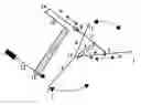
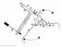
FIG. 1 is a perspective depiction of the invention, Swinky™, the near zero inertia pendulum golf swing trainer set up and linked to a golf club for use by a nice golfer. Arrows indicate adjustability of its components.
(1) The 5/16-inch diameter 1.5-inch tall vertical rubber-capped foot of the free end of each of the tripod's three horizontal legs (4, 5, 6).
(2) The mast angle support slider, integral to tripod neutral leg 4, preset parallel to the lie angle of the club.
(3) The 15-inch-long dual leg pivot assembly. It buttresses the tripod mast support (7) from opposite sides of the nose (15) of leg 4.
(4) The 27-inch-long, 0.5-inch square hollow neutral leg of the tripod.
(5) The 24-inch-long, 0.5-inch square hollow left leg of the tripod.
(6) The 23-inch-long, 0.5-inch square hollow right leg of the tripod.
(7) The tripod hollow mast support (27 inches long by 0.5 inches square) preset parallel to the club shaft. The hinge point of the mast support is ten inches from mast slider (2).
(8) The pendulum mast height-adjustment device.
(9) The 34-inch-long, 0.5-inch square hollow pendulum mast, set to match the height of the golfer's chin at address.
(10) The 0.4 ounce, 3/16-inch outside diameter, ⅛-inch interior diameter hollow thirty-inch-long carbon-fiber pendulum arm hung by its hub/mast axle (14) atop the tripod mast (9, 8, 7).
(11) The heart of the pendulum bob. Its near-weightless visually graphic bridge, a thirty-by-four inch rectangle formed of taut, stretch-resistant thread of 1/16 inch gauge mason's twine at swing address position. One narrow end of the bridge is anchored on the neck of the club shaft (12), the other on the tip of the pendulum arm (10), thus completing the trainer pendulum.
(12) The golf club in its address position. Its lie angle determines mast angle.
(13) The end of the pendulum bob bridge anchored to the neck of the club shaft (12), for example by a noose at the end of each of its two lines separated by a spacer.
(14) The pendulum axle atop the mast (7-9).
(15) The overlap of tripod legs (4, 5, 6) at their hinge point.
DETAILED DESCRIPTION OF THE INVENTION
The invention is a near zero inertial pendulum-based golf swing trainer. Folded up it is about the size of a golf umbrella. It can be unfolded and set up without tools in seconds. Its swing guidance logic is designed to let a user clearly see, feel, and hear how to swing his golf clubs expertly.
See FIG. 1. The top of a mast (14) is preset to be chin-high in front of a golfer. The mast is held aloft by a tripod so the mast is parallel to the shaft of the club the golfer will swing. Atop the mast is the pendulum axle (14) from which swings a pendulum arm (10). It is an extremely rigid 3/16-inch-outside diameter-⅛ inch inside diameter and thirty-inch-long carbon-fiber arrow shaft weighing 0.4 ounces. Consequently the pendulum arm has negligible swing inertia compared to the golf club. The swing period of both the pendulum arm and club is about two seconds.
The pendulum bob bridge rectangle (11) is a pair of thirty-inch long lines of mason's twine that provide graphic visual feedback. Their respective ends are anchored four inches apart, one end anchored on the tip of the pendulum arm, the other on the neck of the club shaft. The golfer completes the pendulum bob by adjusting his swing address position so that the bridge becomes a rectangle with its lines barely taut and free of twist. The bridge rectangle remains unaltered as long the golfer's swing is ideal, namely a circular motion congruent with the longitudinal axis of the mast axle.
Distortion of the rectangle and lurching of the trainer's tripod base signal the onset of a faulty swing move, so all the golfer has to do to swing properly is keep the rectangle whole, whereby the tripod and mast remain steady.
Five thirty-inch-long, ½-inch-square sections of hollow tubing of 0.065-inch wall thickness of either steel or aluminum are preassembled so that each hinge point of the trainer will remain snug for the trainer's useful life. The trainer has a total weight of about six pounds if made of steel or two and a half pounds if made of aluminum. Each section is drilled, bolted to its mate, and the bolts welded, thus forming the snug hinges (2, 3, 7, 15) behind the mast support (7) and tripod's built-in spring suspension system (1, 2, 5, 6, 15).
A key feature of that suspension system is the overlap of the tripod legs (5, 6) at their hinge point (15) under the nose of the third leg (4). Mast slider (2) is machined or injection-molded of acetal resin or equivalent, which can also serve to make the pendulum hub.
A 0.4-ounce carbon-fiber, Kevlar™-fiber, or boron-fiber arrow shaft ( 3/16-inch outside diameter, ⅛-inch inside diameter) thirty inches long (9, 10) with one end anchored through its hub made of ½-inch diameter aluminum tubing of 0.065-inch wall thickness, mounted to mast axle (14) at the top of mast (7, 8, 9) makes the preferred pendulum. The pendulum hangs by its hub on a 0.25-inch diameter brass axle that pivots through the top of the thirty-inch-high mast.
Nylon mason's string makes the pendulum bob bridge with noosed ends for anchorage to club and pendulum arm, four inches apart.
Claims
What is claimed is:1. A near zero inertia pendulum golf swing trainer suitable for anyone swinging a standard golf club, said trainer comprising:
A pendulum hub axle support:
an ultra rigid 0.4 oz wt. pendulum arm with a swing period of about two seconds, which arm may swing freely only around the longitudinal axis of its axle support and bears at its tip:
an offset pendulum bob about 98% of whose total mass is
the mass of the golfer's club at its center of mass near the neck of the club shaft, with
the remaining scant 2% or so of bob mass,
provided by a visually graphic bob bridge of distinct rectangular structure,
composed of taut, strong lines,
one extremity of the bridge anchored on the neck of the golfer's club;
the other extremity anchored on the tip of the pendulum arm;
whereby constant geometry of that bridge rectangle distinctly guides the golfer to swing in a circular path, congruent with the major axis of the pendulum axle support.
2. The rectangular bridge of claim 1 composed of visually graphic lines anchored separately side by side to one another, one end on the neck of the club shaft and the other end on the tip of the pendulum arm;
which two lines, upon becoming free of slack and parallel between the club and pendulum arm when the golfer properly addresses the trainer to swing, subsequently form
a rectangular bridge typically of thirty by four inches that weighs about 0.1 ounces.
3. The rectangular bridge of the trainer of claims 1 and 2, where the lines forming the bridge are twisted together and intersect at their midpoint to form the diagonals of that rectangle rather than its two long sides, whereby maintaining said FIGURE intact induces the golfer to swing the club's center of mass back through its starting position.
4. The pendulum trainer of claim 1, where the pendulum hub axle is carried atop a mast attached to a mast support extending up from and hinged upon the neutral leg of the tripod;
said tripod having three horizontal legs each having a vertical foot at its free end;
two legs being very firmly hinged under the nose end of the third neutral leg, to enable the tripod's three feet to be configured for various levels of stability as necessary to advance a golfer's skill safely.
5. The pendulum swing trainer of claim 4, where the mast angle is adjustable by rotation of the mast support up to 160 degrees with respect to the tripod to preset the swing stability of the trainer according to the golfer's skill.
6. The pendulum trainer of claim 5, where the height of the mast is adjustable by extending or retracting it from its support.
7. The pendulum trainer of claim 4, where the distance between the feet of the tripod coupled with firm hinging of two legs below the nose of the neutral leg endows the trainer with a type of spring-leaf suspension, ensuring desirable swing recoil stability.
8. The pendulum trainer of claim 1, where the swing inertia accrued by the pendulum and bob is so tiny compared to that of the swung club that the mast and tripod barely sway, unless the golfer's swing is faulty.
9. The pendulum trainer of claim 1, where the pendulum arm is a premium-grade 0.4-ounce ( 3/16 inch outside diameter, ⅛-inch inside diameter) hollow arrow shaft, commonly referred to by archers as a “carbon fiber” or “boron fiber” or “Kevlar™ fiber,” or combination thereof, arrow shaft.
10. The pendulum bob of claim 1, where the taut lines composing the rectangular perimeter are twisted together to form a bridge/rectangle having conspicuous intersecting diagonals and imaginary long sides.
11. The tripod of claim 2, comprising hinged ½-inch square hollow legs, fastened together to permit the tripod to fold up or to be unfolded numerous times to form a robust stand-alone robotic structure without tools which is essentially maintenance-free.
12. The tripod of claim 2, where the mast angle is set by sliding its articulated base along the neutral leg of the tripod, and rotating the mast/pendulum arm 180 degrees.
13. The mast and pendulum of the trainer of claim 1, where the unit is removed from the device and swung to simulate the batting or racket-swinging action of other sports.
Images & Drawings included:
Sources:
- United States Patent and Trademark Office - verify current appl. status at the USPTO↗
Recent applications in this class:
- » 20250144500 2025-05-08
PUTT PATH TRAINING DEVICE - » 20250144499 2025-05-08
Putting Practice Device - » 20250128136 2025-04-24
SYSTEM, METHOD AND/OR COMPUTER READABLE MEDIUM FOR DETERMINING READ OF A PUTT - » 20250083019 2025-03-13
SYSTEMS AND METHODS FOR CALCULATING A CRITICAL VELOCITY OF A PUTT USING A MOBILE DEVICE - » 20250083018 2025-03-13
SYSTEMS AND METHODS FOR CALCULATING AN OPTIMAL PUTTING LINE AND PUTTING STROKE VIA A MOBILE DEVICE - » 20250073558 2025-03-06
Shaw Slope Gauge / Simple Green Reading - » 20250058196 2025-02-20
GOLF PUTTING APPARATUS - » 20250010161 2025-01-09
GOLF SIMULATOR SYSTEM AND METHOD - » 20240416208 2024-12-19
Elevated Putting Apparautus: Trainer and Game - » 20240399229 2024-12-05
TRAINING DEVICE