Bumper beam with integrated energy absorber
US20110254295A1
2011-10-20
13/066,134
2011-04-07
✅ Patent granted
US 8,439,411 B2
2013-05-14
-
-
Lori Lyjak
Warn Partners, P.C.
2031-07-25
Abstract:
The present invention is directed to an energy absorbing component externally mounted to a vehicle having a beam structural member and at least one energy absorber operably connected to the beam structural member. The energy absorber absorbs energy when the vehicle undergoes a collision. Also included is a beam cover plate connected to the beam structural member through the use of resistive implant welding, which simplifies the manufacturing process, and improves manufacturing costs. There are two vehicle attachment plates which are overmolded to the beam cover plate, the vehicle attachment plates allow for the beam cover plate to be attached to a vehicle. The beam cover plate, beam structural member, and energy absorber form a component that is operable to function as a bumper that is connected to a vehicle, which absorbs energy during a collision.
Inventors:
- Alan C. Cave 3 🇨🇦 Mount Forest, Canada
- Robert Dernovsek 4 🇨🇦 Guelph, Canada
- Richard W. Haveman 1 🇨🇦 Newmarket, Canada
Assignee:
- Magna International Inc. 334 🇨🇦 Aurora, Canada
Applicant:
Interested in similar patents?
Get notified when new applications in this technology area are published.
Classification:
B60R19/03 » CPC main
Wheel guards; Radiator guards, e.g. grilles ; Obstruction removers; Fittings damping bouncing force in collisions; Bumpers, i.e. impact receiving or absorbing members for protecting vehicles or fending off blows from other vehicles or objects characterised by material, e.g. composite
B29C65/342 » CPC further
Joining of preformed parts ; Apparatus therefor by heating, with or without pressure using heated elements which remain in the joint, e.g. "verlorenes Schweisselement" characterised by the type of heated elements which remain in the joint comprising at least a single wire, e.g. in the form of a winding
B29C65/344 » CPC further
Joining of preformed parts ; Apparatus therefor by heating, with or without pressure using heated elements which remain in the joint, e.g. "verlorenes Schweisselement" characterised by the type of heated elements which remain in the joint being a woven or non-woven fabric or being a mesh
B29C66/1312 » CPC further
General aspects of processes or apparatus for joining preformed parts; General aspects dealing with the joint area or with the area to be joined; Particular design of joint configurations particular design of the joint cross-sections; Single flanged joints; Fin-type joints; Single hem joints; Edge joints; Interpenetrating fingered joints; Other specific particular designs of joint cross-sections not provided for in groups - ; Single flanged joints, i.e. one of the parts to be joined being rigid and flanged in the joint area Single flange to flange joints, the parts to be joined being rigid
B29C66/543 » CPC further
General aspects of processes or apparatus for joining preformed parts; General aspects of joining tubular articles; General aspects of joining long products, i.e. bars or profiled elements; General aspects of joining single elements to tubular articles, hollow articles or bars; General aspects of joining several hollow-preforms to form hollow or tubular articles; Joining tubular articles, profiled elements or bars; Joining single elements to tubular articles, hollow articles or bars; Joining several hollow-preforms to form hollow or tubular articles; Joining several hollow-preforms, e.g. half-shells, to form hollow articles, e.g. for making balls, containers; Joining several hollow-preforms, e.g. half-cylinders, to form tubular articles joining more than two hollow-preforms to form said hollow articles
B29C66/545 » CPC further
General aspects of processes or apparatus for joining preformed parts; General aspects of joining tubular articles; General aspects of joining long products, i.e. bars or profiled elements; General aspects of joining single elements to tubular articles, hollow articles or bars; General aspects of joining several hollow-preforms to form hollow or tubular articles; Joining tubular articles, profiled elements or bars; Joining single elements to tubular articles, hollow articles or bars; Joining several hollow-preforms to form hollow or tubular articles; Joining several hollow-preforms, e.g. half-shells, to form hollow articles, e.g. for making balls, containers; Joining several hollow-preforms, e.g. half-cylinders, to form tubular articles one hollow-preform being placed inside the other
B29C66/72141 » CPC further
General aspects of processes or apparatus for joining preformed parts characterised by the composition, physical properties or the structure of the material of the parts to be joined; Joining with non-plastics material characterised by the structure of the material of the parts to be joined; Fibre-reinforced materials characterised by the length of the fibres Fibres of continuous length
B29C66/73921 » CPC further
General aspects of processes or apparatus for joining preformed parts characterised by the composition, physical properties or the structure of the material of the parts to be joined; Joining with non-plastics material characterised by the intensive physical properties of the material of the parts to be joined, by the optical properties of the material of the parts to be joined, by the extensive physical properties of the parts to be joined, by the state of the material of the parts to be joined or by the material of the parts to be joined being a thermoplastic or a thermoset characterised by the material of the parts to be joined being a thermoplastic or a thermoset characterised by the material of at least one of the parts being a thermoplastic characterised by the materials of both parts being thermoplastics
B60R19/22 » CPC further
Wheel guards; Radiator guards, e.g. grilles ; Obstruction removers; Fittings damping bouncing force in collisions; Bumpers, i.e. impact receiving or absorbing members for protecting vehicles or fending off blows from other vehicles or objects; Means within the bumper to absorb impact characterised by the cross-section; containing mainly cellular material, e.g. solid foam
B29C65/3476 » CPC further
Joining of preformed parts ; Apparatus therefor by heating, with or without pressure using heated elements which remain in the joint, e.g. "verlorenes Schweisselement" characterised by the composition of the heated elements which remain in the joint being metallic
B29L2031/3044 » CPC further
Other particular articles; Vehicles, e.g. ships or aircraft, or body parts thereof Bumpers
B60R2019/184 » CPC further
Wheel guards; Radiator guards, e.g. grilles ; Obstruction removers; Fittings damping bouncing force in collisions; Bumpers, i.e. impact receiving or absorbing members for protecting vehicles or fending off blows from other vehicles or objects; Means within the bumper to absorb impact characterised by the cross-section;; Structural beams therefor, e.g. shock-absorbing made of plastic material Blow moulded
B60R2019/1866 » CPC further
Wheel guards; Radiator guards, e.g. grilles ; Obstruction removers; Fittings damping bouncing force in collisions; Bumpers, i.e. impact receiving or absorbing members for protecting vehicles or fending off blows from other vehicles or objects; Means within the bumper to absorb impact characterised by the cross-section;; Additional energy absorbing means supported on bumber beams, e.g. cellular structures or material Cellular structures
B60R2019/1886 » CPC further
Wheel guards; Radiator guards, e.g. grilles ; Obstruction removers; Fittings damping bouncing force in collisions; Bumpers, i.e. impact receiving or absorbing members for protecting vehicles or fending off blows from other vehicles or objects; Means within the bumper to absorb impact characterised by the cross-section; Bumper fascias and fastening means therefor
B29C66/7212 » CPC further
General aspects of processes or apparatus for joining preformed parts characterised by the composition, physical properties or the structure of the material of the parts to be joined; Joining with non-plastics material characterised by the structure of the material of the parts to be joined; Fibre-reinforced materials characterised by the composition of the fibres
B29K2309/08 » CPC further
Use of inorganic materials not provided for in groups - , as reinforcement Glass
B29C66/71 » CPC further
General aspects of processes or apparatus for joining preformed parts characterised by the composition, physical properties or the structure of the material of the parts to be joined; Joining with non-plastics material characterised by the composition of the plastics material of the parts to be joined
B29K2023/12 » CPC further
Use of polyalkenes or derivatives thereof as moulding material; Polymers of propylene PP, i.e. polypropylene
B60R19/26 IPC
Wheel guards; Radiator guards, e.g. grilles ; Obstruction removers; Fittings damping bouncing force in collisions; Bumpers, i.e. impact receiving or absorbing members for protecting vehicles or fending off blows from other vehicles or objects; Arrangements for mounting bumpers on vehicles comprising yieldable mounting means
B32B37/04 IPC
Methods or apparatus for laminating, e.g. by curing or by ultrasonic bonding characterised by the partial melting of at least one layer
B60R19/38 IPC
Wheel guards; Radiator guards, e.g. grilles ; Obstruction removers; Fittings damping bouncing force in collisions; Bumpers, i.e. impact receiving or absorbing members for protecting vehicles or fending off blows from other vehicles or objects; Arrangements for mounting bumpers on vehicles adjustably or movably mounted, e.g. horizontally displaceable for securing a space between parked vehicles
Description
CROSS-REFERENCE TO RELATED APPLICATIONS
This application claims priority to U.S. Provisional Application No. 61/342,159 filed on Apr. 9, 2010. The disclosure of the above application is incorporated herein by reference.
FIELD OF THE INVENTION
The present invention relates to an energy absorbing component for a bumper or fascia made of a composite material.
BACKGROUND OF THE INVENTION
Most motor vehicles in use today have some type of bumper or fascia mounted to the front end and rear end of the vehicle. Current designs for most bumpers have some sort of device or component which is used for absorbing energy during a collision. This reduces the amount of energy transferred to the occupants of the vehicle.
However, components used for absorbing energy during a collision of most current designs are made of metal, which is costly to manufacture. Accordingly, there exists a need for a bumper which includes a component able to absorb energy during a vehicle collision, with the component being made of a composite material.
SUMMARY OF THE INVENTION
The present invention is directed to an energy absorbing component externally mounted to a vehicle having a beam structural member and at least one energy absorber operably connected to the beam structural member. The energy absorber absorbs energy when the vehicle undergoes a collision.
Also included is a beam cover plate connected to the beam structural member through the use of resistive implant welding, which simplifies the manufacturing process, and improves manufacturing costs. There are two vehicle attachment plates which are overmolded to the beam cover plate, the vehicle attachment plates allow for the beam cover plate to be attached to a vehicle.
The beam structural member and the beam cover plate are made from injection molded long glass fiber nylon material, and the energy absorber is made from expanded polypropylene using a steam injection molding process.
The beam cover plate, beam structural member, and energy absorber form a component that is operable to function as a bumper that is connected to a vehicle, which absorbs energy during a collision.
Further areas of applicability of the present invention will become apparent from the detailed description provided hereinafter. It should be understood that the detailed description and specific examples, while indicating the preferred embodiment of the invention, are intended for purposes of illustration only and are not intended to limit the scope of the invention.
BRIEF DESCRIPTION OF THE DRAWINGS
The present invention will become more fully understood from the detailed description and the accompanying drawings, wherein:
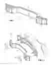
FIG. 1 is a first perspective view of a bumper beam having an integrated energy absorber, according to the present invention;
FIG. 2 is an exploded view of a bumper beam having an integrated energy absorber, according to the present invention
FIG. 3 is an enlarged sectional side view of section 3-3 in FIG. 1;
FIG. 4 is a second perspective view of a bumper beam having an integrated energy absorber, according to the present invention;
FIG. 5 is a front view of a beam structural member used as part of a bumper beam having an integrated energy absorber, according to the present invention;
FIG. 6 is an enlarged perspective view of a beam cover plate used as part of a bumper beam having an integrated energy absorber, according to the present invention;
FIG. 7 is a front view of a vehicle attachment plate used as part of a bumper beam having an integrated energy absorber, according to the present invention;
FIG. 8 is a rear view of a vehicle attachment plate used as part of a bumper beam having an integrated energy absorber, according to the present invention; and
FIG. 9 is a sectional view taken along lines 9-9 of FIG. 8.
DETAILED DESCRIPTION OF THE PREFERRED EMBODIMENTS
The following description of the preferred embodiment(s) is merely exemplary in nature and is in no way intended to limit the invention, its application, or uses.
A bumper beam having an integrated energy absorber is shown in the Figures generally at 10. The bumper beam 10 includes a beam cover plate 12, a beam structural member 14, and a foam energy absorber 16. The cover plate 12, beam structural member 14, and foam energy absorber 16 are all connected together, with the beam structural member 14 located between the cover plate 12 and the foam energy absorber 16.
Both the cover plate 12 and the beam structural member 14 are made of molded long glass fiber (LGF) nylon; they are connected by resistance implant welding (RIW). The foam energy absorber 16 is made from expanded polypropylene (EPP) material using a steam injection molding process, and is fastened to the beam structural member 14.
Also included is a plurality of vehicle attachment plates 18. In this embodiment, the attachment plates 18 are in the form of steel brackets 18, which are overmolded into the beam cover plate 12. The steel brackets 18 are made of 1008/1010 steel, and are suitable for connection with a vehicle.
The steel brackets 18 each have a front side 20 which mounts to the vehicle rails (not shown) and a rear side 22 which faces the fascia (also not shown). As mentioned above, the steel brackets 18 are overmolded into the beam cover plate 12, as shown by the shaded areas in FIGS. 7 and 8. Referring to FIG. 9, a sectional view along the side of one of the brackets 18 is shown. The brackets 18 have several apertures 24, and a portion of the overmolded material 26 which makes up the beam cover plate 12 flows through two of the apertures 24 during the overmolding process. The overmold material 26 has a thickness 28 of about five millimeters and extends beyond the edge 30 of each aperture 24 a distance 32 of about five millimeters. The remaining apertures 24 are used for connecting the brackets 18 to the vehicle rails.
As mentioned above, the cover plate 12 and the beam structural member 14 are connected by RIW. Referring to FIG. 3, an enlarged sectional view of the cover plate 12 and beam structural member 14 are shown. The cover plate 12 has a first welding flange 30 and the beam structural member 14 has a second welding flange 32. The first welding flange 30 substantially circumscribes the cover plate 12, and the second welding flange 32 substantially circumscribes the beam structural member 14.
Disposed between each of the flanges 30,32 is an implant 34. To connect the cover plate 12 and the beam structural member 14, the cover plate 12 is positioned relative to the beam structural member 14 such that the first welding flange 30 contacts the second welding flange 32, and the implant 34 is located in between. A current is applied to the implant 34, heating the implant 34, thereby melting a first melt surface 36 of the first welding flange 30 and a second melt surface 38 of the second welding flange 32. Melting the surfaces allows for some of the material of each melt surface 36,38 to flow across the implant 34. Once the current is no longer applied to the implant 34, the implant 34 and melt surfaces 36,38 cool, and the first welding flange 30 and second welding flange 32 become interconnected together. When connected, the beam structural member 14 and the cover plate 12 form a closed section, or structural “box” section.
While the implant 34 shown in FIG. 3 is a wire mesh made of stainless steel, it is within the scope of the invention that the implant 34 may be of other shapes and made from other materials, such as copper, aluminum, brass, nickel, and titanium.
Referring to FIGS. 4-6, the cover plate 12 and the beam structural member 14 have a plurality of ribs 40 which are used for improving the strength of the cover plate 12 and the beam structural member 14. While it has been shown in FIGS. 4-6 that the ribs 40 connected to the cover plate 12 are oriented horizontally, and the ribs 40 connected to the beam structural member 14 are diagonal, it is within the scope of the invention that the ribs 40 on both the cover plate 12 and the beam structural member 14 may be formed of different shapes and orientations, depending on how the cover plate 12 and beam structural member 14 are to be reinforced.
The bumper beam 10 of the present invention incorporates the novel features of the structural member 14 and energy absorber 16 connected and functioning as a single part when connected to a vehicle, with the energy absorber 16 functioning to absorb energy in a collision. Additionally, the structural member 14 and energy absorber 16 are connected through the use of RIW to form an enclosed section tubular structure, which improves efficiency and reduces cost of manufacturing.
The description of the invention is merely exemplary in nature and, thus, variations that do not depart from the essence of the invention are intended to be within the scope of the invention. Such variations are not to be regarded as a departure from the spirit and scope of the invention.
Claims
What is claimed is:1. An energy absorbing component externally mounted to a vehicle, comprising:
a beam structural member operable for attachment to a vehicle; and
at least one energy absorber operably connected to said beam structural member such that said at least one energy absorber absorbs energy when said vehicle undergoes a collision.
2. The energy absorbing component incorporated into an external component of a vehicle of claim 1, further comprising a beam cover plate connected to said beam structural member to form a closed section.
3. The energy absorbing component incorporated into an external component of a vehicle of claim 2, wherein said beam cover plate is connected to said beam structural member through resistive implant welding.
4. The energy absorbing component incorporated into an external component of a vehicle of claim 3, further comprising:
a first welding flange formed as part of said beam cover plate;
a second welding flange formed as part of beam structural member; and
an implant disposed between said first welding flange and said second welding flange such that when said implant is heated, at least a portion of said first welding flange and a portion of said second welding flange melt, and when said implant is no longer heated, said implant cools, and said first welding flange integrally molds with said second welding flange, connecting said beam cover plate to said beam structural member.
5. The energy absorbing component incorporated into an external component of a vehicle of claim 2, wherein said beam cover plate is made from injection molded long glass fiber nylon material.
6. The energy absorbing component incorporated into an external component of a vehicle of claim 2, further comprising at least one vehicle attachment plate overmolded to said beam cover plate, said vehicle attachment plate operable for connection with a vehicle.
7. The energy absorbing component incorporated into an external component of a vehicle of claim 6, said at least one vehicle attachment plate further comprising a plurality of apertures, wherein a portion of an overmold material used for creating said beam cover plate extends through one or more of said plurality of apertures as said at least one vehicle attachment plate is overmolded to said beam cover plate.
8. The energy absorbing component incorporated into an external component of a vehicle of claim 1, wherein said beam structural member is made from injection molded long glass fiber nylon material.
9. The energy absorbing component incorporated into an external component of a vehicle of claim 1, wherein said at least one energy absorber is made from expanded polypropylene using a steam injection molding process.
10. The energy absorbing component incorporated into an external component of a vehicle of claim 1, further comprising a plurality of ribs, a portion of said plurality of ribs being formed as part of said beam cover plate, and a portion of said plurality of ribs being formed as part of said beam structural member.
11. A method for creating a component for absorbing energy during a collision, comprising the steps of:
providing a beam structural member;
providing at least one energy absorber;
providing a beam cover plate;
providing at least one vehicle attachment plate operable for connection with a vehicle;
connecting said beam cover plate to said beam structural member through resistive implant welding;
overmolding said at least one vehicle attachment plate to said beam cover plate;
connecting said at least one energy absorber to said beam structural member such that said at least one energy absorber absorbs energy when said vehicle undergoes a collision.
12. The method for creating a component for absorbing energy during a collision of claim 11, further comprising the steps of creating said beam cover plate from injection molded long glass fiber nylon material.
13. The method for creating a component for absorbing energy during a collision of claim 11, further comprising the steps of creating said beam structural member from injection molded long glass fiber nylon material.
14. The method for creating a component for absorbing energy during a collision of claim 11, further comprising the steps of creating said at least one energy absorber from expanded polypropylene using a steam injection molding process.
15. The method for creating a component for absorbing energy during a collision of claim 11, further comprising the steps of forming a closed box section when said beam cover plate is connected to said beam structural member.
16. The method for creating a component for absorbing energy during a collision of claim 11, further comprising the steps of:
providing a first welding flange formed as part of said beam cover plate;
providing a second welding flange formed as part of said beam structural member;
providing an implant disposed between said first welding flange and said second welding flange;
melting at least a portion of said first welding flange and a portion of said second welding flange by applying a current to and heating said implant; and
integrally molding said first welding flange with said second welding flange by cooling said implant by removing said current from said implant, connecting said beam cover plate to said beam structural member.
17. The method for creating a component for absorbing energy during a collision of claim 11, further comprising the steps of:
providing a plurality of apertures formed as part of said vehicle attachment plate; and
extending at least a portion of an overmold material used for creating said beam cover plate through one or more of said plurality of apertures as said at least one vehicle attachment plate is overmolded to said beam cover plate.
18. The method for creating a component for absorbing energy during a collision of claim 11, further comprising the steps of:
providing a plurality of ribs;
forming a portion of said plurality of ribs as part of said beam cover plate; and
forming a portion of said plurality of ribs as part of said beam structural member.
19. An energy absorbing component externally mounted to a vehicle, comprising:
a beam structural member;
at least one energy absorber;
a beam cover plate connected to said beam structural member through resistive implant welding; and
at least one vehicle attachment plate connected to a vehicle, said at least one vehicle attachment plate overmolded to said beam cover plate.
20. The energy absorbing component externally mounted to a vehicle of claim 19, wherein said beam cover plate is made from injection molded long glass fiber nylon material.
21. The energy absorbing component externally mounted to a vehicle of claim 19, wherein said beam cover plate and said beam structural member formed as closed box section when said beam cover plate is connected to said beam structural member.
22. The energy absorbing component externally mounted to a vehicle of claim 19, said at least one vehicle attachment plate further comprising a plurality of apertures, wherein a portion of an overmold material used for creating said beam cover plate extends through one or more of said plurality of apertures as said at least one vehicle attachment plate is overmolded to said beam cover plate.
23. The energy absorbing component incorporated into an external component of a vehicle of claim 19, further comprising:
a first welding flange formed as part of said beam cover plate;
a second welding flange formed as part of beam structural member; and
an implant disposed between said first welding flange and said second welding flange such that when said implant is heated, at least a portion of said first welding flange and a portion of said second welding flange melt, and when said implant is no longer heated, said implant cools, and said first welding flange integrally molds with said second welding flange, connecting said beam cover plate to said beam structural member.
24. The energy absorbing component incorporated into an external component of a vehicle of claim 19, further comprising a plurality of ribs, a portion of said plurality of ribs being formed as part of said beam cover plate, and a portion of said plurality of ribs formed as part of said beam structural member.
25. The energy absorbing component externally mounted to a vehicle of claim 19, wherein said beam structural member is made from injection molded long glass fiber nylon material.
26. The energy absorbing component externally mounted to a vehicle of claim 19, wherein said at least one energy absorber is made from expanded polypropylene using a steam injection molding process.
Images & Drawings included:


Sources:
- United States Patent and Trademark Office - verify current appl. status at the USPTO↗
Recent applications in this class:
- » 20250100492 2025-03-27
MULTI-TUBULAR BEAM - » 20230062947 2023-03-02
MULTI-TUBULAR BEAM WITH FORGED WELD SEAM - » 20220118928 2022-04-21
VEHICLE BUMPER, COMPOSITE MATERIALS FOR VEHICLE BUMPERS, AND METHODS THEREOF - » 20220105885 2022-04-07
Bumper for vehicle - » 20220063530 2022-03-03
Vehicle component for a vehicle - » 20220041123 2022-02-10
MULTI-LAYER MOTOR VEHICLE EXTERIOR PART COMPRISING A HEATING ELEMENT - » 20220009434 2022-01-13
Lightweight rear bumper beam - » 20210370857 2021-12-02
Vehicle back beam and vehicle including same - » 20210245687 2021-08-12
Wooden bumper assembly - » 20210107417 2021-04-15
Vehicular shock-absorbing member
Recent applications for this Assignee:
- » 20240367268 2024-11-07
QUALITY MONITORING OF WELDING PROCESS - » 20240263739 2024-08-08
NON-CIRCULAR PRESSURE VESSEL - » 20240173767 2024-05-30
Conformal cooling insert - » 20240093538 2024-03-21
MODULAR INDIVIDUALLY OPERABLE VEHICLE DOOR - » 20240075657 2024-03-07
AUTOMATIC CLEANING SYSTEM AND METHOD FOR REMOVING DEBRIS FROM DIES - » 20240042629 2024-02-08
Robotic assembly - » 20230264544 2023-08-24
AUTOMOTIVE SIDE DOOR STRUCTURE - » 20230182199 2023-06-15
Smart trim die assembly - » 20230145522 2023-05-11
Method for producing a joining connection between metal sheets - » 20230130566 2023-04-27
Seat thermal management and positional sensing