Triangular inflatable evacuation slide
US20110259668A1
2011-10-27
12/672,438
2008-08-28
✅ Patent granted
US 8,376,082 B2
2013-02-19
WO; PCT/AU2008/001262; 20080828
WO; WO2009/026631; 20090305
James O Hansen | Kristine Florio
Edwin D. Schindler
2029-08-14
Abstract:
An inflatable evacuation slide, substantially triangular in cross-section, includes a base and lateral sides. The sides are formed from interlocking components, so that the slide is straight, when deployed. The inflatable evacuation slide may be used, for example, as a marine evacuation slide.
Applicant:
Interested in similar patents?
Get notified when new applications in this technology area are published.
Classification:
B63B27/143 » CPC main
Arrangement of ship-based loading or unloading equipment for cargo or passengers of ramps, gangways or outboard ladders ; Pilot lifts Ramps
B64D25/14 » CPC further
Emergency apparatus or devices, not otherwise provided for; Ejecting or escaping means Inflatable escape chutes
E01D15/122 » CPC further
Movable or portable bridges; Floating bridges; Portable or sectional bridges Inflatable or unreelable bridges ; Bridges with main load-supporting structure consisting only of non-rigid elements, e.g. cables
B63B2027/145 » CPC further
Arrangement of ship-based loading or unloading equipment for cargo or passengers of ramps, gangways or outboard ladders ; Pilot lifts; Ramps Inflatable ramps
B63C9/00 IPC
Life-saving in water
B63B27/00 IPC
Arrangement of ship-based loading or unloading equipment for cargo or passengers
A62B1/20 » CPC further
Devices for lowering persons from buildings or the like by making use of sliding-ropes, sliding-poles or chutes, e.g. hoses, pipes, sliding-grooves, sliding-sheets
Description
AREA OF THE INVENTION
This invention relates to the area of marine safety equipment and in particular to a slide to be used in association with a liferaft.
BACKGROUND TO THE INVENTION
For many years the use of conventional lifeboats on board ships presented problems with respect to on board stowage, release and passenger loading. The latter two functions being effected only with the deployment of considerable manpower.
With the more recent development of inflatable liferafts however these require means for quickly and safely loading passengers.
This desirability for quick, safe evacuation procedures in turn led to the development of inflatable slides which are used by passengers to slide into the liferaft which is deployed in the water. These slides are known to rapidly inflate such that passengers can be quickly evacuated.
In order to improve passenger safety liferaft slides of this type have been developed which are relatively enclosed, to prevent a passenger falling, while being generally triangular in cross-section to increase both strength and stability.
These inflatable slides do however have the disadvantage that not only will they sag with the weight of occupants on the slide but are known to sag downwards under their own weight. This in turn increases the risk of “buckling” under load.
OUTLINE OF THE INVENTION
It is the object of this invention to provide in a marine evacuation system an inflatable evacuation slide which has a structure such that the slide is self supporting under its own weight when inflated and also when it is loaded with passengers.
The invention is an inflatable evacuation slide which slide is generally triangular in cross section and includes a base and lateral sides, said sides being structured from interlocking components such that the slide is straight when deployed.
It is preferred that the evacuation slide be deployed between a vessel and a liferaft.
It is further preferred that the lateral sides be comprised of a series of adjacent interlocking components which in a preferred embodiment of the invention are generally triangular and inverted generally triangular inflated members.
It is also preferred that the slide when inflated be straight under both its own weight and that of those using it for marine evacuation purposes.
In order that the invention may be more readily understood we shall describe by way of non limiting example a specific embodiment of the invention with reference to the accompanying drawing figures.
BRIEF DESCRIPTION OF THE DRAWING FIGURES
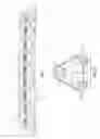
FIG. 1 Shows a side view of the slide of the invention when not under load;
FIG. 2 Shows an end view of the slide of FIG. 1;
FIG. 3 Shows a side view of a conventional marine evacuation slide;
FIG. 4 Shows an end view of the slide of FIG. 3;
DESCRIPTION OF AN EMBODIMENT OF THE INVENTION
In the preferred embodiment of the invention a 20m slide is described although the concept of the invention applies generally to evacuation slides. These slides are subject to a combination of bending loads acting perpendicular to the slide and compressive loads acting parallel to the slide.
Most evacuation slides deflect or bend under their own weight which increases a slide's susceptibility to buckling deformation. In contrast the slide of the invention is designed and manufactured such that it becomes straight under its own weight when deployed.
The rigidity of the slide 10 is provided by forming the sides from interlocking generally triangular frames 20 that join to each other as well as the main slide frame 30 and top tubes 40, the angles of the triangular frames being determined such that when joined together an upwardly directed bend 50 in the slide is formed which straightens under the weight of the slide when inflated and deployed.
In contrast a conventional marine evacuation slide is shown in FIG. 3 and as can be seen the side brace tube assemblies 60 used to strengthen the lateral sides 65 are unconnected to each other and do not act to prevent movement which will lead to sagging under its own weight even in the absence of any additional passenger load.
The marine evacuation slides are triangular in cross-section as shown in FIGS. 2 and 4 as this is a shape which provides the simplest structurally sound mode of construction. The length of the slide used will also vary depending on the drop height required. The embodiment of the invention described however is 20m in length.
As discussed here conventional slides (shown in FIG. 2) tend to sag under their own weight and the more a slide sags the more susceptible it becomes to both buckling loads and bending loads thereby impairing its required function.
The slide design of the invention as shown in FIG. 1 provides a pre bending arrangement 50 to the outstretched uninflated slide which directs it arcuately above the horizontal as shown.
When the slide is inflated the interlocking frames 20 act upon one and other when the slide is deployed such that, while any residual sag causes the slide to become straight, further downwards movement of the base 30 of the slide is restricted by the slide structure.
This result is achieved by the use of the tesselated interlocking triangular side braces as shown. While the precise shape of these members is not restricted in the invention the arrangement shown in FIG. 1 has proved to be most effective.
In this embodiment of the invention all the individual inflatable tubes of the slide are manufactured from a polyurethane coated nylon fabric using high frequency welding techniques.
The material used to manufacture these tubes is not restricted in the invention neither are the bonding and fabrication techniques used in manufacture in general, however all materials and methods of manufacture must comply with the relevant legislative requirements.
The base of the slide may be of any type preferred and is also not restricted in the invention neither is a strictly triangular cross section although the latter is preferred for strength considerations.
While the triangular side bracing members used to form the side walls of the slide are unique to the invention any slide construction which provides for an initially arcuately shaped slide base and orientation, which becomes straight when the slide is inflated, lies within the scope of the invention as does the use of tesselated side frame members.
Other design features of the slide relevant to materials used and details of interior bracing and the like can also be varied in the invention.
The invention described here provides a structurally sound evacuation slide for a liferaft which safely encloses the evacuating passengers and maintains its required shape in use and while we have described here one specific embodiment of the invention it is to be understood that variations and modifications in this can be made without departing from the spirit and scope of the invention.
Claims
1-7. (canceled)
8. An inflatable evacuation slide, comprising:
a base; and,
lateral sides extending from said base and comprised of interlocking components for maintaining said inflatable evacuation slide substantially straight when said inflatable evacuation slide is in a deployed position, said inflatable evacuation slide being substantially triangular in cross-section.
9. The inflatable evacuation slide according to claim 8, wherein said inflatable evacuation slide has an arcuate shape along its length, when not under load, prior to placement into the deployed position.
10. The inflatable evacuation slide according to claim 8, wherein said interlocking components of said lateral sides have a shape so that said interlocking components prevent said inflatable evacuation slide from sagging, when inflated.
11. The inflatable evacuation slide according to claim 8, wherein said interlocking components comprise a series of adjacent substantially triangular and inverted triangular inflated members.
12. The inflatable evacuation slide according to claim 11, where said substantially triangular and inverted triangular inflated members are frame members.
Images & Drawings included:


Sources:
- United States Patent and Trademark Office - verify current appl. status at the USPTO↗
Recent applications in this class:
- » 20250026453 2025-01-23
Boat-Attachable Diving Board and Walking Plank Device - » 20250026452 2025-01-23
SYSTEM FOR MANOEUVRING A MARINE CRAFT - » 20240300621 2024-09-12
Recovery Ramp - » 20240124101 2024-04-18
Inflatable, Floatable Water Exit Ramp System - » 20230303221 2023-09-28
LAUNCH AND RECOVERY OF UNDERWATER UNITS OR VEHICLES - » 20220411027 2022-12-29
MADWATER HINGE - » 20220119077 2022-04-21
Attachable loading ramp for modular floating vessel platforms - » 20210291938 2021-09-23
Modular ramp system for a landing craft - » 20200391828 2020-12-17
Hinge system and a portable gangway using the hinge system - » 20200239111 2020-07-30
Device for transferring personnel and/or goods from a surface vessel to an offshore structure or to another vessel