Axle for a motor vehicle
US20110260424A1
2011-10-27
13/128,699
2009-12-09
✅ Patent granted
US 8,556,282 B2
2013-10-15
WO; PCT/EP2009/066660; 20091209
WO; WO2010/072563; 20100701
Ruth Ilan
Davis & Bujold, PLLC
2030-03-09
Abstract:
An axle for a motor vehicle comprises at least a transverse leaf spring (1) attached directly, or via an auxiliary support frame, to a body (9) of the motor vehicle by two first mountings (4), two control arms (2) and two wheel carriers (3). In each case, an end of the transverse leaf spring (1) facing toward a respective wheel (10) of the motor vehicle is rigidly connected to one of the two control arms (2), and both of the two control arms (2) are each orientated substantially in the longitudinal direction of the motor vehicle. Each of the control arms (2) is connected by a second mounting (7) directly, or via an auxiliary support frame, to the body (9) and also connected, by at least one third mounting (5, 6), to one of the wheel carriers (3).
Inventors:
- Stephan Pollmeyer 10 🇩🇪 Friedrichshafen, Germany
- Volker Wagner 14 🇩🇪 Ravensburg, Germany
- Gabriele Fruhmann 8 🇦🇹 Bregenz, Austria
- Stephan Pollymeyer 1 🇩🇪 Friedrichshafen, Germany
Assignee:
- ZF FRIEDRICHSHAFEN AG 3,767 🇩🇪 Friedrichshafen, Germany
Applicant:
Interested in similar patents?
Get notified when new applications in this technology area are published.
Classification:
B60G3/28 » CPC further
Resilient suspensions for a single wheel with two or more pivoted arms, e.g. parallelogram at least one of the arms itself being resilient, e.g. leaf spring
B60G7/001 » CPC further
Pivoted suspension arms; Accessories thereof Suspension arms, e.g. constructional features
B60G2200/141 » CPC further
Indexing codes relating to suspension types; Independent suspensions with lateral arms with one trailing arm and one lateral arm only
B60G2200/1422 » CPC further
Indexing codes relating to suspension types; Independent suspensions with lateral arms with a single lateral arm, e.g. MacPherson type the lateral arm being resilient
B60G2200/46 » CPC further
Indexing codes relating to suspension types; Indexing codes relating to the wheels in the suspensions camber angle
B60G2202/114 » CPC further
Indexing codes relating to the type of spring, damper or actuator; Type of spring; Leaf spring transversally arranged
B60G2204/121 » CPC further
Indexing codes related to suspensions or to auxiliary parts; Mounting of suspension elements; Mounting of springs or dampers Mounting of leaf springs
B60G2204/143 » CPC further
Indexing codes related to suspensions or to auxiliary parts; Mounting of suspension elements; Mounting of suspension arms on the vehicle body or chassis
B60G2204/148 » CPC further
Indexing codes related to suspensions or to auxiliary parts; Mounting of suspension elements; Mounting of suspension arms on the unsprung part of the vehicle, e.g. wheel knuckle or rigid axle
B60G2204/82 » CPC further
Indexing codes related to suspensions or to auxiliary parts; Interactive suspensions; arrangement affecting more than one suspension unit left and right unit on same axle
B60G2204/8302 » CPC further
Indexing codes related to suspensions or to auxiliary parts; Interactive suspensions; arrangement affecting more than one suspension unit; Type of interconnection Mechanical
B60G2206/0114 » CPC further
Indexing codes related to the manufacturing of suspensions: constructional features, the materials used, procedures or tools; Constructional features of suspension elements, e.g. arms, dampers, springs; Modular constructions Independent suspensions on subframes
B60G2206/15 » CPC further
Indexing codes related to the manufacturing of suspensions: constructional features, the materials used, procedures or tools; Constructional features of suspension elements, e.g. arms, dampers, springs; Constructional features of arms the arm being resilient
B60G2206/7101 » CPC further
Indexing codes related to the manufacturing of suspensions: constructional features, the materials used, procedures or tools; Constructional features of suspension elements, e.g. arms, dampers, springs; Materials used in suspensions; Light weight materials Fiber-reinforced plastics [FRP]
B60G3/10 » CPC main
Resilient suspensions for a single wheel with a single pivoted arm the arm being essentially transverse to the longitudinal axis of the vehicle the arm itself being resilient, e.g. leaf spring
B60G11/08 » CPC further
Resilient suspensions characterised by arrangement, location or kind of springs having leaf springs only arranged substantially transverse to the longitudinal axis of the vehicle
Description
This application is a National Stage completion of PCT/EP2009/066660 filed Dec. 9, 2009, which claims priority from German patent application serial no. 10 2008 054 669.0 filed Dec. 15, 2008.
FIELD OF THE INVENTION
The present invention relates to an axle for a motor vehicle.
BACKGROUND OF THE INVENTION
From DE 10221993 B4 a wheel suspension system for non-steered wheels of motor vehicles is known, with a lower transverse control arm of torsionally rigid structure articulated to the vehicle body or to an auxiliary support frame, onto which a wheel carrier is articulated at two mounting points, and with two further individual control arms also articulated above it to the body and to the wheel carrier, such that one mounting point between the lower transverse control arm and the wheel carrier is designed to be flexible in the transverse direction. In this case one of the mounting points is formed by two bearings nested in one another, of which the bearing that co-operates with the transverse control arm is a torsion bearing and the bearing that co-operates with the wheel carrier is a thrust pressure bearing, such that the bearing can be loaded under thrust in the transverse direction and under pressure in the vertical direction.
Furthermore, from WO 96/27507 a wheel suspension system for a vehicle axle with two wheels is known, which has a transverse leaf spring with two-point mounting and a respective wheel carrier in each case, wherein a one-piece, continuous and wheel-guiding composite-material transverse leaf spring is provided, which consists of plastic reinforced with mostly longitudinally orientated technically continuous filaments. In this known wheel suspension system the two-point mounting has high rigidity in the transverse direction; the composite-material transverse leaf spring has a spring constant in the driving direction and a spring constant in the vertical direction, such that the ratio of these spring constants relative to one another is at least 15 and at articulation points the ends of the leaf spring are articulated directly to the wheel carriers. In this case a wheel-guiding element that supports longitudinal and transverse forces is provided, which connects the wheel carriers flexibly to the chassis so that, with the transverse leaf spring and the wheel-guiding element, all the wheel forces can be absorbed.
SUMMARY OF THE INVENTION
The purpose of the present invention is to provide an axle for a motor vehicle, which is characterized by high function integration; in addition the axle according to the invention should be lighter than those known from the prior art. Thereby, on the one hand cost savings should be achieved and on the other hand the kinematics should be influenced positively.
According to these, an axle for a motor vehicle is proposed which comprises at the least a transverse leaf spring preferably in the form of a fiber-composite component, and two control arms and two wheel carriers. According to the invention the transverse leaf spring is fixed to a body of the motor vehicle by two first mountings, either directly or via an auxiliary support frame, such that in each case an end of the transverse leaf spring facing toward a wheel of the motor vehicle is rigidly connected to one of the control arms, which is orientated substantially in the longitudinal direction of the motor vehicle. In this case the control arms are in each case connected, directly or via an auxiliary support frame, to the body by a respective second mounting and, in each case by at least one respective third mounting, to one of the wheel carriers. Thereby, the bearings together with the wheel-facing ends of the transverse leaf spring form a wheel-guiding element which takes over the function of a trapezoidal link.
Advantageously, by virtue of the four-point mounting of the transverse leaf spring formed by the rigid connections to the control arms at the ends and by the attachments to the body of the motor vehicle, both vertical and rolling suspension can be realized, with the result that the body springs and stabilizers known from the prior art can be omitted.
According to the invention a camber control arm connected to the respective wheel carriers can be provided, which is connected to the body directly or via an auxiliary support frame.
As already explained, the axle components can be connected to the vehicle body both directly or via an auxiliary support frame, and when the axle components are attached by means of a support frame this enables the axle to be pre-assembled. Compared with an ordinary steel structure, making the transverse leaf spring as a fiber-composite component results in substantial weight advantages and high elasticity. As fiber materials, glass fibers, carbon fibers or aramide fibers are preferred.
In a preferred embodiment, the axle according to the invention is a non-steered axle of a motor vehicle.
BRIEF DESCRIPTION OF THE DRAWINGS
Below, an example of the invention is explained in more detail with reference to the attached figures, which show:
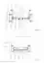
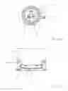
FIG. 1: Schematic plan view of the wheel suspension system of an axle according to the invention;
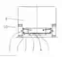
FIG. 2: Schematic front view of the wheel suspension system of an axle according to the invention;
FIG. 3: Schematic side view of the wheel suspension system of an axle according to the invention, as seen from inside;
FIG. 4: Schematic front view of the wheel suspension system in FIG. 2, during uniform deflection;
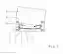
FIG. 5: Schematic front view of the wheel suspension system in FIG. 2, during non-uniform deflection.
DETAILED DESCRIPTION OF THE PREFERRED EMBODIMENTS
FIGS. 1, 2, 3, 4 and 5 illustrate an axle of a motor vehicle designed according to the invention. The axle comprises a transverse leaf spring 1, which is attached to the body 9 of the motor vehicle directly or via an auxiliary support frame by two first mountings 4. In particular, the first mountings 4 are preferably in the form of rubber-metal mountings in order to ensure high mobility of the transverse leaf spring 1 relative to the body 9.
As can be seen from FIGS. 1, 2, 3, 4 and 5, the end of the transverse leaf spring 1 facing each wheel 10 is connected rigidly to a respective control arm 2, the control arms 2 being orientated substantially in the longitudinal direction 11 of the motor vehicle; in FIG. 1 the forward driving direction of the motor vehicle is indicated by the arrow.
Referring to FIG. 1, the control arms 2 are each connected by a respective second mounting 7, directly or via an auxiliary support frame, to the vehicle body 9 and in each case by two third mountings 5, 6 to the respective wheel carrier 3, so that together with the wheel-facing ends of the transverse leaf spring 1 a wheel-guiding element is produced, which takes over the function of a conventional trapezoidal link.
As can be seen particularly clearly in FIG. 2, each wheel carrier 3 is associated with a camber control arm 8 connected to it, which is connected to the body 9 directly or via an auxiliary support frame.
By virtue of the four-point mounting of the transverse leaf spring 1 produced by the first mountings 4 and the rigid connections to the control arms 2, effective vertical and roll suspension is realized so that, in an advantageous manner, the body springs and stabilizers known from the prior art can be omitted. This is made clear by FIGS. 4 and 5, which show a front view of the axle corresponding to FIG. 2, but respectively, during uniform and non-uniform deflection.
In FIG. 4, the wheels 10 are uniformly deflected, for example as the motor vehicle drives over a road bump extending transversely to the driving direction, whereby the transverse leaf spring 1 is elastically stressed and adopts a U-shape. During this, via the first mountings 4 the transverse leaf spring 1 pushes the body 9 back to the rest position shown in FIG. 2 and thus fulfills the function of a vertical spring. In contrast, in FIG. 5 the body 9 is pushed in a sideways direction, for example while driving round a curve, so that only one of the wheels 10 is deflected relative to the body 9. During this, under elastic stress the transverse leaf spring 1 adopts an S-shape and, again via the first mountings 4, pushes the body 9 back to its rest position, thus fulfilling the function of a stabilizer.
In a further design version of the invention the control arms 2 are also fiber-composite components, which is in particular being advantageous with regard to weight.
INDEXES
- 1 Transverse leaf spring
- 2 Control arm
- 3 Wheel carrier
- 4 First mounting
- 5 Third mounting
- 6 Third mounting
- 7 Second mounting
- 8 Camber control arm
- 9 Vehicle body
- 10 Wheel
- 11 Longitudinal direction
Claims
1-5. (canceled)
6. An axle for a motor vehicle, the axle comprising:
at the least a transverse leaf spring (1) attached either directly, or via an auxiliary support frame, to a body (9) of the motor vehicle by a pair of first mounting (4),
two control arms (2), and
two wheel carriers (3),
wherein, in each case, an end of the transverse leaf spring (1), facing toward a respective wheel (10) of the motor vehicle, is rigidly connected to one of the two control arms (2), and the two control arms (2) are both orientated substantially in a longitudinal direction of the motor vehicle,
each of the two control arms (2) is connected by a second mounting (7) either directly, or via an auxiliary support frame, to the body (9), and
each of the two control arms (2) is connected by at least one third mounting (5, 6) to one of the two wheel carriers (3).
7. The axle for a motor vehicle, according to claim 6, wherein a camber control arm (8), associated with each of the two wheel carrier (3), is connected thereto, and is connected either directly or via an auxiliary support frame to the body (9).
8. The axle for a motor vehicle, according to claim 6, wherein the transverse leaf spring (1) is manufactured as a fiber-composite component.
9. The axle for a motor vehicle, according to claim 6, wherein each of the first mounting (4) is in the form of rubber-metal bearings.
10. The axle for a motor vehicle, according to claim 6, wherein the control arms (2) are manufactured as a fiber-composite components.
11. An axle for a motor vehicle, the axle comprising:
a transverse leaf spring (1) fixed to a body (9) of the motor vehicle by a pair of first mountings (4),
two control arms (2), and
two wheel carriers (3),
the transverse leaf spring (1) having two opposed ends that are remote from each other and adjacent a respective wheel (10) of the motor vehicle, each of the two opposed ends of the transverse leaf spring (1) being rigidly connected to a respective one of the two control arms (2),
the two control arms (2) being orientated in a substantially longitudinal direction of the motor vehicle, and each of the two control arms (2) being connected by a second mounting (7) to the body (9) of the motor vehicle, and
each of the two control arms (2) being connected, by at least one third mounting (5, 6), to one of the wheel carriers (3).
Images & Drawings included:
Sources:
- United States Patent and Trademark Office - verify current appl. status at the USPTO↗
Similar patent applications:
- » 20110227402
Motor vehicle axle component and method for producing a motor vehicle axle component - » 20240048071
METHOD AND APPARATUS FOR OPERATING AT LEAST ONE SWITCHING DEVICE OF A POWER CONVERTER FOR AN ELECTRICAL AXLE DRIVE OF A MOTOR VEHICLE, POWER CONVERTER SYSTEM FOR AN ELECTRICAL AXLE DRIVE OF A MOTOR VEHICLE, ELECTRICAL AXLE DRIVE FOR A MOTOR VEHICLE AND MOTOR VEHICLE - » 20230391188
COMMERCIAL MOTOR VEHICLE, AUXILIARY AXLE FOR COMMERCIAL MOTOR VEHICLE, DEVICE AND METHOD FOR CONTROLLING THE COUPLING AND/OR UNCOUPLING BETWEEN AN AXLE OF A COMMERCIAL MOTOR VEHICLE AND AN AUXILIARY MOTOR - » 20240344600
Transmission device for a motor vehicle, drive axle, and motor vehicle - » 20240183420
Axle Support Bearing for a Motor Vehicle Axle Driven in Particular by Means of an Electric Motor - » 20240408976
Method for Operating a Drive Axle for a Motor Vehicle, Control Unit, Drive Axle, and Motor Vehicle - » 20170297398
Axle component for a motor vehicle axle - » 20140151945
Arrangement for holding a first fastening element and a second fastening element on an axle element for a motor vehicle axle - » 20240116312
Spring Seat Body for a Rigid Axle of a Motor Vehicle and Rigid Axle for a Motor Vehicle With a Spring Seat Body - » 20080272569
Structural motor vehicle axle system assembled by structural bonding
Recent applications in this class:
- » 20160031277 2016-02-04
Refurbishment assembly for heavy duty chassis and method - » 20140131971 2014-05-15
Independent suspension system with self-compensated floating swing arm - » 20130093155 2013-04-18
Shock Absorber Structure of Wheelchair Front Fork - » 20100032921 2010-02-11
Suspension apparatus for vehicle - » 20080007022 2008-01-10
Suspension Apparatus - » 20070163071 2007-07-19
Self-propelled sweeper including a front steering axle - » 20050127634 2005-06-16
Arm for a motor-vehicle independent suspension system and a motor-vehicle independent suspension system comprising the arm
Recent applications for this Assignee:
- » 20250293169 2025-09-18
STACKABLE POWER SEMICONDUCTOR MODULE - » 20250292970 2025-09-18
CAPACITIVE WINDING OF A DC LINK CAPACITOR AND DC LINK CAPACITOR WITH A COMMON-MODE CURRENT LEAKAGE FUNCTION - » 20250286013 2025-09-11
APPARATUS AND METHOD FOR MANUFACTURING A POWER SEMICONDUCTOR DEVICE - » 20250283529 2025-09-11
DRIVE UNIT FOR A VEHICLE - » 20250282215 2025-09-11
MOTOR VEHICLE TRANSMISSION FOR AN AT LEAST PARTIALLY ELECTRICALLY DRIVEN MOTOR VEHICLE - » 20250282209 2025-09-11
DRIVE UNIT FOR A VEHICLE - » 20250269709 2025-08-28
ARTICULATED RIGID AXLE OF A VEHICLE WITH AN AXLE SUPPORT WITH AN ELECTRIC MACHINE AS DRIVE - » 20250262892 2025-08-21
AXLE SUPPORT SYSTEM FOR A VEHICLE AXLE - » 20250256806 2025-08-14
BATTERY TERMINAL FOR TWO-WHEELED VEHICLES HAVING AN ELECTRIC DRIVE UNIT - » 20250251033 2025-08-07
GEARBOX AND DRIVE UNIT WITH SUCH A GEARBOX