Butterfly push-pull pin
US20110268535A1
2011-11-03
12/769,085
2010-04-28
✅ Patent granted
US 8,317,445 B2
2012-11-27
-
-
Flemming Saether
2030-12-16
Abstract:
The Butterfly Push-Pull Pin (also referred to as a force advantageous push-pull pin in this application) is a practical fastener used to support penetrable (pierceable) materials on supporting material such as a bulletin board, notice board, tack board, wall or other element penetrable by a push (driven) pin. In the Butterfly Push-Pull Pin, two broad, sloped, opposing sides of a polygonal handle are grasped to push the pin in. Two other broad, sloped, opposing sides of the polygonal handle are used to pull the pin out.
Interested in similar patents?
Get notified when new applications in this technology area are published.
Classification:
B43M15/00 » CPC main
Drawing-pins, Thumb-tacks
F16B19/00 IPC
Bolts without screw-thread; Pins, including deformable elements ; Rivets
F16B15/02 IPC
Nails; Staples with specially-shaped heads, e.g. with enlarged surfaces
Description
REFERENCES CITED
U.S. Patent Documents
| Pat. No. | Patent Date | Inventor | |
| 317,090 | May 1885 | Cave, et al. | |
| 434,650 | August 1890 | Adams | |
| 451,213 | April 1891 | Shipley | |
| 654,319 | July 1900 | Moore | |
| 752,925 | February 1904 | Ryan | |
| 793,123 | June 1905 | Carroll | |
| 885,687 | April 1908 | Chenoweth | |
| 975,235 | November 1910 | Hansen | |
| 978,185 | December 1910 | McMillan | |
| 1,076,983 | October 1913 | Jerrim | |
| 1,991,561 | February 1935 | Krantz | |
| D,149,099 | March 1948 | Sweet | |
| D,175,275 | August 1955 | Romine | |
| 4,897,007 | January 1990 | Chen, et al. | |
| 6,132,060 | October 2000 | Gallo | |
| 6,409,445B1 | June 2002 | Beale | |
| 6,406,241 | June 2002 | Lorincz | |
| D,466,937 | December 2002 | Kochlefl et al. | |
BACKGROUND OF THE INVENTION
Push pins, as the expression is used here, are pins which are pushed through a material or materials requiring support, then into a supporting material. Push pins were first patented in the late 19th Century. This type of push pin is comprised, commonly, of two components: a handle and a pin, which are intended to remain together as a unit. The push pins are typically used to support materials in temporary or changeable circumstances and they are pushed in (driven) by human force and pulled out (removed) by human force. The devices that are known by, and described by, the expression “push pin,” typically are operated in the push and pull modes. They might be more properly identified as push-pull pins, but the expression push-pin is commonly used in descriptions of prior art and in common practice by people who use such devices. A typical use of push pins would be to support drawings on a vertical or sloped bulletin board or tack board, for example.
As can be seen in the prior art referenced in this application, the handles on available push pins offer small areas of purchase to grasp between thumb and finger, or between two fingers, in order to drive the push pin into supporting material. With prior art, when driving a push pin into supporting material, the procedure often is difficult because the thumb and finger contact surfaces of the pin handles lack sufficient surface area, the shape of the handle is difficult to grasp securely, or the shape of the handle does not naturally direct efficient force toward the supporting material. A person intending to drive in a push pin, with stability, often has to pinch, or squeeze, the handle so firmly, parallel to the surface of the supporting material rather than perpendicular (the drive in direction), that limited energy is available to push the pin into the supporting material. Due to limited contact area in many prior art devices, thumb and finger, or fingers, often slide off the push pin handle before the pin is properly embedded in the supporting material. Due to prior art shape—geometry—there is often limited pushing surface for driving the push pin efficiently into supporting material. Due to prior art geometry, in order to grasp and drive in the push pin, many people must use more than two digits.
In prior art, even less attention has been paid to the process of pulling the pin out of the supporting material, axially opposite the pushing direction. The contact area is so small and the handle shape is so difficult to grasp that, again, an inefficient pinching energy is required and often the thumb and finger slide off the pin handle before the pin has been removed from the supporting material.
Furthermore, in prior art, in the process of removing a pin from supporting material, the handle sometimes pulls off the pin, leaving the pin in the supporting material. When this happens, the push pin unit no longer functions as intended. A mechanical tool, such as a pair of pliers, is required to remove the separated pin from the supporting material.
The inventor in this patent application has used common, prior art push pins for several years and it is because of his annoyance and frustration in using this prior art that he created the present invention.
SUMMARY OF THE INVENTION
The present invention, the Butterfly Push-Pull Pin, is a very practical fastener used to support penetrable (pierceable) materials on a bulletin board, notice board, tack board, wall or other element penetrable by a push (driven) pin. In the butterfly push-pull pin, two broad, sloped, opposing sides of the polygonal handle are grasped by a user's thumb and opposing finger, or two fingers, to push the pin in, and the user's thumb and opposing finger, or two fingers, are used to pull the pin out, using the other two broad, sloped, opposing sides of the polygon. The broad sides give advantageous purchase to the acts of pushing and pulling and the sloped geometry of the sides assists in alignings energy in the proper axial direction to either push or pull the push-pull pin. Therefore, the push-pull pin is force advantageous because it provides, in its geometry, an advantageous means of forcing the pin into supporting material and an advantageous means of pulling the pin out of the supporting material. The opposing push and pull faces of the polygonal handle enable a user to push or pull the pin more easily than prior art, using one finger and a thumb, or two fingers.
OBJECTS AND ADVANTAGES
Several objects and advantages of the present invention are:
-
- (a) To provide a force advantageous, stable, easy means to push (drive), the device through material to be supported and into supporting material.
- (b) To provide a force advantageous, stable, easy means to pull (extract) the pin from supporting material.
- (c) To provide improved safety over prior art.
- (d) To prevent the unintended separation of the push pin handle and the pin.
BRIEF DESCRIPTION OF THE INVENTION DRAWINGS
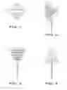
FIGS. 1, 2, 3, 4, 5 and 6 illustrate the butterfly push-pull pin.
FIG. 1 is a plan (top) view of the invention,
FIG. 2 is a perspective view of the invention,
FIG. 3 is a front elevation and rear elevation of the perspective, in which the raised ribs of the push sides are visible,
FIG. 4 is a left side elevation and right side elevation of the invention, in which the pull sides are visible,
FIG. 5 is a perspective view thereof, as pulled (extracted), and
FIG. 6 is a perspective view thereof, as pushed (driven).
REFERENCED NUMERALS IN THE DRAWINGS
-
- 1. Polygonal push-pull handle
- 2. Pin with one deformed embedded end and with one taper exposed end terminating in a point.
DETAILED DESCRIPTION OF THE EMBODIMENT
A preferred embodiment of the present invention is illustrated in FIGS. 1, 2, 3, 4, 5 and 6. The butterfly push-pull pin is one unit comprised of two components, which are permanently affixed to one another: a polygonal handle and a deformed, embedded pin.
The purpose of the present invention, the Butterfly Push-Pull Pin, is to support penetrable (pierceable) materials on supporting material such as a bulletin board, notice board, tack board, wall or other element penetrable by a push (driven) pin.
In the Butterfly Push-Pull Pin, two broad, sloped, opposing sides of the polygonal handle are grasped by a user's thumb and opposing finger, or two fingers, to push the pin in, as indicated in FIG. 6. The user's thumb and opposing finger, or two fingers, are used to pull the pin out, using the other two broad, sloped, opposing sides of the polygon, as indicated in FIG. 5. The present invention exhibits novelty in that, although push pins with the same intended purpose were first patented more than 100 years ago and several types of push pins have been patented since, none of the prior art provides the geometry and consequential force advantage of the present invention and none of the prior art indicates a deformed pin embedment intended to prevent unintentional extraction. Therefore, the present invention was not obvious to anyone of ordinary skill in the art of making push pins.
Polygonal Push-Pull Handle Component:
-
- (a) The polygonal handle has a long and narrow bottom face and a face of the same size at the top, turned 90 degrees to the like face at the bottom, as indicated in FIGS. 1 and 2. Connecting these two faces are four equal size trapezoidal faces, as indicated in FIGS. 1, 2, 3, 4, 5, and 6. The two long and narrow faces and the four trapezoidal faces form a closed, six-sided polygon which is comprised of solid material and is not hollow. The outermost three-dimensional limits of the handle fit precisely within the limits of a cubic (equal-sided) volume. In the preferred embodiment, this volume is approximately ¾″ by ¾″ by ¾″, and it could be larger and it could be smaller. The polygonal handle in the present invention can be fabricated from readily available materials and it can be manufactured by anyone skilled in the art of making push pins.
- (b) The polygonal handle may be made of various materials, such as metals, plastics and wood. The handle material may be formed and pressed around the deformed pin or it may be cast around the deformed pin, in a manner which mechanically engages the deformed pin, in order to prevent separation of the handle and the pin. Also, the polygonal handle may be machined from existing material in which a hole is drilled or punched into the bottom face to receive the deformed pin. This hole is formed with an opening which permits the pin to be embedded, and the inset, deepest, end of the hole is slightly larger. Alternatively, the surface of the made hole may be deformed by means of coarse drilling or chemical etching, for example. The pin is then set into the hole with glue and when the glue cures to a hardened state, the resultant mechanical connection—created by pre-cure flow of the glue into the deformations of the pin and deformations of the hole in the handle—prevents separation of the handle and pin.
- (c) The raised ribs, as indicated in FIGS. 1, 2, 3, 4, 5 and 6, of the push faces of the handle assist in grasping and removing the pin from storage (when not already stored in driven position) and in retaining the push-pull pin between two digits prior to driving it through material to be supported and into supporting material. It is preferred that each push face of the polygonal handle have at least one raised rib. It is within the skill of those in the art to vary the number of the ribs. It is well within the skill of those in the art to vary the rib configuration on each of the push faces, such that the ribs may extend less than the full width of the push faces, or they may be situated diagonally or they may be present in a grid or diagrid formation on the push faces. It is well within the skill of those in the art to add ribs, as described for the push faces, on the pull faces. It is well within the skill of those in the art to construct the push and pull faces of the polygonal handle with grooves rather than raised ribs, grooves being the obverse of raised ribs.
Pin with One Deformed End and One Tapered End Terminating in a Point Component: - (a) The pin is made of metal and is novel in that one end—the end embedded in the polygonal handle—is deformed, as indicated in FIGS. 3 and 4. The deformation is such that the portion of the pin that is embedded is linearly non-uniform and widened. When the polygonal handle is cast, formed or glued around the embedded deformation, the resultant interlocking geometry prevents the pin from unintentionally and disbeneficially sliding out of, and separating from, the polygonal handle. The pin is deformed prior to being embedded in the polygonal handle and the deformation may be imparted by means of a pinching action or other process which, by means of force perpendicular to the axis of the pin, deforms the shape of the embedded face of the pin.
- (b) The pin end opposite the embedded end is tapered and terminates in a point, so that it may be driven into supporting material.
Advantages
On its own and compared with prior art, the present invention, the Butterfly Push-Pull Pin, offers the following advantages based on the description above:
-
- (a) The polygonal handle geometry provides a force advantageous, stable, easy means to push (drive), the device through material to be supported and into supporting material.
- (b) The polygonal handle geometry provides a force advantageous, stable, easy means to pull (extract) the pin from supporting material.
- (c) The polygonal handle geometry provides improved safety over prior art.
- (d) The deformed, embedded end of the pin prevents the unintended separation of the push pin handle and the pin.
Alternative Physical Forms of the Present Invention
The above description of the present invention should not be construed to limit physical manifestations of the Butterfly Push-Pull Pin to the exact characterization shown in the drawings. Alterations within the claims may include, but not be limited to:
-
- (a) Beveled or radiused edges instead of arrises formed by the intersections of polygonal handle faces;
- (b) Alternative layout of ribs in the push faces;
- (c) Grooves instead of ribs in the push faces;
- (d) Coarse texture on the push faces instead of ribs;
- (e) Ribs, grooves or coarse texture on the pull faces;
- (f) Alternative polygonal handle materials;
- (g) Elastically deformable, tactile-responsive, polygonal handle material;
- (h) Alternative pin materials;
- (i) Alternative pin deformation types in the embedded area of the pin such as drill outs, embossing, hooking etc, in an industrially efficient manner which, when the polygonal handle is formed around the embedment, causes the polygonal handle and pin to engage inseparably;
- (j) The depth of the embedment could be increased.
CONCLUSION
In view of the description above, the present invention, the force advantageous Butterfly Push-Pull Pin, represents a major departure from the work exhibited in prior art. It offers improved ease, efficiency and stability of means, in driving the push pin into supporting material and in pulling it out of supporting material. In addition, the end of the pin embedded in the polygonal handle is deformed and when the polygonal handle is cast, formed or glued around the deformed embedment, the handle and pin are made into one unit. When the Butterfly Push-Pull Pin is extracted from supporting material, the embedded end of the driven pin will remain in the polygonal handle and it will not remain in the supporting material, as sometimes happens with prior art.
The Butterfly Push-Pull Pin derives its name from the common insect of the order Lepidoptera. The physical form of the present invention is, strictly in coincidence, an abstraction of Lepidoptera physical form.
Claims
I claim:1. A force advantageous push-pull pin comprising:
(a) A three-dimensional polygonal handle which, with force, provides efficient means to drive an embedded pin through material to be supported and into supporting material.
(b) A pin comprising a deformed end and a pointed end, with said polygonal handle formed around said deformed end, as a means to maintain said polygonal handle and said embedded pin inseparable, as one unit.
Images & Drawings included:


Sources:
- United States Patent and Trademark Office - verify current appl. status at the USPTO↗
Recent applications in this class:
- » 20230373238 2023-11-23
TARGET RETAINING DEVICE - » 20140348614 2014-11-27
Article for Securing Multiple Materials - » 20120134766 2012-05-31
Planar sheet mounting device and frame - » 20120110794 2012-05-10
MAGNETIC SAFETY PUSHPIN - » 20120020757 2012-01-26
Safety tack - » 20100263174 2010-10-21
Magnetic safety pushpin - » 20100158636 2010-06-24
TACK SET FOR USE ON BULLETIN BOARDS - » 20100107373 2010-05-06
Device for releasably securing to a support surface - » 20100000057 2010-01-07
DRAWING PIN HAVING FUNCTIONALITY OF DRAWING BACK AUTOMATICALLY - » 20080008559 2008-01-10
Paper tack