Method for demodulating signals from a multi-access system able to collide and equipment for implementing same
US20110280347A1
2011-11-17
13/105,410
2011-05-11
✅ Patent granted
US 8,693,587 B2
2014-04-08
-
-
Young T. Tse
Baker Hostetler LLP
2032-06-04
Abstract:
A method for demodulating time-multiplexed signals able to mutually collide, in particular in the case of an AIS (Automatic Identification System), being a communications system between ships allows collisions between these ships to be limited and allows the maritime traffic in view from the coasts to be monitored thanks to coastal stations that listen to the communications. When these colliding signals are sufficiently “distinct” (in frequency, in power or in time), algorithms exist for discriminating between them. The demodulator offers the possibility of demodulating two colliding signals, whose collision parameters (difference in frequency, in power or their non-synchronization) are sufficiently small to make them virtually inaccessible otherwise. The method and equipment allow the satellite AIS system to utilize cases of signal collisions that were hitherto detrimental in order to improve the overall performance.
Inventors:
- Thibaud Calmettes 15 🇫🇷 Toulouse, France
- Jérémie GIRAUD 1 🇫🇷 CANNES LA BOCCA, France
- Jérémie Giraud 1 🇫🇷 Cannes la Bocca Cedex, France
Assignee:
- THALES 1,536 🇫🇷 NEUILLY SUR SEINE, France
- CENTRE NATIONAL D'ETUDES SPATIALES 135 🇫🇷 Paris, France
Applicant:
Interested in similar patents?
Get notified when new applications in this technology area are published.
Classification:
H04L25/03331 » CPC main
Baseband systems; Details ; arrangements for supplying electrical power along data transmission lines; Shaping networks in transmitter or receiver, e.g. adaptive shaping networks; Arrangements for removing intersymbol interference; Arrangements involving sequence estimation techniques Arrangements for the joint estimation of multiple sequences
H04L27/2017 » CPC further
Modulated-carrier systems; Phase-modulated carrier systems, i.e. using phase-shift keying; Modulator circuits; Transmitter circuits for continuous phase modulation in which the phase change within each symbol period is constrained in which the phase changes are non-linear, e.g. generalized and Gaussian minimum shift keying, tamed frequency modulation
H04L27/227 » CPC further
Modulated-carrier systems; Phase-modulated carrier systems, i.e. using phase-shift keying; Demodulator circuits; Receiver circuits using coherent demodulation
H04L27/06 IPC
Modulated-carrier systems; Amplitude-modulated carrier systems, e.g. using on-off keying; Single sideband or vestigial sideband modulation Demodulator circuits; Receiver circuits
Description
The present invention relates to a method for demodulating signals of a multi-access system with transmission according to a multiplexing protocol, in which two signals can mutually collide when they arrive simultaneously at a receiver. The invention is more particularly, but not exclusively, applicable to AIS signals.
Amongst the known signals of the time-multiplexed type are those of the AIS system. The AIS (Automatic Identification System) is a public communications system between ships which allows collisions between these ships to be limited and which allows the maritime traffic in view from the coasts to be monitored thanks to coastal stations that listen to the communications. This system advantageously implements satellites for relaying the communications over a wide area. In order to allow the satellite AIS to have an acceptable performance with respect to the performance demands for maritime safety, the highest possible number of tools must be implemented to utilize the colliding signals in order to extract the message from at least one of them.
The circumstances in which signals can collide are many-fold. The colliding signals come from different SO-TDMA (Self Organizing Time Division Multiple Access) cells. The differences in frequency (Doppler), power (distance/free-space loss, antenna gain) and synchronization (distance/propagation time) between these various signals are variable which can allow their discrimination.
Solutions do exist (simple demodulator, SIC or “Sequential Interference Canceller”) that provide access to at least one of the colliding signals, in the case where there are a sufficient number of parameters discriminating between them: difference in synchronization, difference in carrier or difference in power.
When the said parameters of two signals are too close, the performance in terms of bit error rate is seriously degraded. In particular, in the worst case of collision between two signals (i.e. signals received at the same power and with identical Doppler frequencies), access to the two signals becomes impossible.
The article “Co-Channel Demodulation for Continuous-Phase Modulated Signals, Peter A. Murphy & Gary E. Ford, IEEE proceedings” discloses a method, the “Joint Maximum Likelihood Sequence Estimation (J-MLSE)”, providing possibilities for demodulation of two signals in certain collision circumstances, encountered in cellular communications systems. Thus, this method is applicable in the case of two signals with the same carrier frequency and whose digital contents are synchronized when they are received. This type of method therefore seems to be valid, but in circumstances that are too restrictive, which will not be encountered in other systems, such as in particular the satellite AIS.
The subject of the present invention is a method for demodulating two signals, of a multi-access system with transmission according to a multiplexing protocol, that can mutually collide, these two signals having digital contents that are synchronized or not when they are received and carrier frequencies, affected by the Doppler, identical or not, this method allowing the detection performance of such signals to be improved, in particular for AIS signals.
The method according to the invention is a method for demodulating two signals able to mutually collide, these signals being those of a multi-access system with transmission according to a multiplexing protocol and with phase modulation of the signals to be transmitted by all the transmitters of the system, a synchronization in time, frequency and phase having been carried out on these signals, and it is characterized in that it consists, on reception, during the demodulation, in measuring the value of the phase of the global signal formed by these two signals and in determining the value of the phase states of each of these two signals and hence their digital contents using the Viterbi method to eliminate ambiguities produced for cases where the phases of the two signals are separated by kπ.
The Viterbi demodulation consists, in the case where the two signals are “confounded”, in other words having the same carrier frequency and whose bit transitions coincide, in performing the following iterations: as a first step, measure the phase of the global signal sampled at the bit transition times, which will therefore be common to the two signals; as a second step, estimate, depending on the pair of phase states (one for each signal S1 and S2) coming from the preceding iteration, and for each scenario for a received pair of bits (one for each signal S1 and S2), the expected value of the global phase, this estimated phase being a function of the differences in power of the two signals, in phase states of the two signals, and also in values of phase difference of these two signals due to different path lengths (φoff1 and φoff2); as a third step, calculate the metric associated with each scenario for a received bit pair, this metric being the distance between the measured and estimated global phases; and as a final step, conserve the bit-stream pair (one for each signal S1 and S2) offering the smallest aggregate metric, this aggregate metric being the sum of the aggregate metric calculated in the preceding iteration and of the metric calculated in the third step of the current iteration.
The present invention will be better understood upon reading the detailed description of one embodiment, taken by way of non-limiting example and illustrated by the appended drawings, in which:
FIGS. 1 to 3 are phase diagrams showing the principle of conventional GMSK modulation construction for the signals transmitted by an AIS system, which signals the invention processes during the demodulation when they are received,
FIGS. 4 to 8 are diagrams of an example of determination of the value of the phase and Fresnel states for each of two mutually colliding AIS signals, according to the present invention.
The present invention is described hereinbelow with reference to two signals coming from two different ships and communicating on the same AIS system. It is assumed that these two signals mutually collide when they are received in a processing centre (which may form part of the payload of a satellite for an AIS signal listening system, or else may be a mission or control centre for various other systems), but it will be clearly understood that the invention is not limited to these AIS signals, and that it can be implemented in any communications system multiplexed in the time domain (TDMA), in the frequency domain (FDMA) or by spectral spreading (CDMA) in which several users may wish to simultaneously access the multiplexing system, and for which it is desired to avoid mutual blocking of the requests for access.
It will be noted that, for the collisions of more than two signals, which is statistically sufficiently likely for it to be a consideration, the method of the invention would be difficult to implement directly. This is because:
- in the case of two signals, the method of the invention consists, for one phase state of the global signal, in:
- either pointing to a single pair of phase states for the two component signals,
- or pointing to two pairs, and the ambiguity is then lifted by virtue of the Viterbi decoding;
- in the case of three signals, the number of combinations is too large: a phase state of the global signal will very probably result in a too large a number of phase state triplets and there will generally be too many ambiguities that will be irresolvable. However, it is possible to wait for a favourable frame (with two colliding signals) in order to resolve this problem as described here.
The present invention starts from the existing principle of coherent demodulation of multi-signal assemblies modulated by phase coding, in this case GMSK (Gaussian Minimum-[phase]-Shift Keying) modulation then extends it to the case where the received signal is a sum (in other words a collision) of two signals with similar characteristics. It will be clearly understood that GMSK modulation is not the only one that can be implemented by the invention, and that other phase modulations may be used, such as MSK (for unsynchronized incident signals).
The method of the invention is implemented after synchronization of the two mutually colliding received signals. This synchronization is applied to the time information (by marking the bit transitions of the signal undergoing synchronization), to the frequency information (by identifying the carrier frequency of the signal undergoing synchronization) and to the phase information (by determining the absolute phase of the signal undergoing synchronization). Such a synchronization is possible for the AIS by performing correlations of the received signal with “training sequences”, which are sequences of bits contained in each signal and known to the users of the AIS system. Once the synchronization has been carried out on each signal, the total signal is demodulated (in order to lower it in frequency) using the carrier measured on the strongest signal, and the total signal is sampled at the bit transition times of the strongest signal. By convention, in the following part of the description, the strongest signal is denoted S1 and the weakest signal S2.
The method of the invention essentially consists in determining the value of the phase of the global signal formed from two colliding signals, and in determining the values of the phase states of each of these two signals and hence their digital contents using the Viterbi method to eliminate ambiguities produced for cases where the phases of the two signals are separated by kπ.
It is recalled here that, in the case of the AIS, the GMSK modulation of the signals transmitted by the various ships of the same system is constructed as follows: the phase of the transmitted signal is subjected to a ramp of π/2 radians (over the duration of a bit) when the transmitted bit value is 1, and −π/2 radians when the transmitted bit value is 0. In addition, a Gaussian low-pass filter is applied to the transmitted signal, after MSK modulation.
When an AIS signal is received at the control centre, the value of the phase of the signal depends on:
- φs(n): The phase state transmitted by the ship, at the moment of transmission (linked to the bits contained in the message),
- φoff: the phase offset, linked to the distance travelled between the ship and the receiver,
- φd(n): the residual phase drift linked to the frequency synchronization errors.
Hereinbelow, the case of two signals received simultaneously is considered.
In order to describe the solution of the invention, the case is firstly considered where:
- These two signals S1, S2 are “confounded”: they have the same carrier frequency and the bit transitions coincide,
- The components φoff1 and φoff2 are random components (linked to the distances travelled by each signal),
- A perfect synchronization in time and in frequency is carried out on the signal S1 (assumed to have the higher power).
The solution of the invention is based on two main mechanisms:
-
- 1. Knowing the value of the phase of the global signal (sum of the two component signals), it is possible to deduce the value of the phase states of each of the two colliding AIS signals. To illustrate this possibility, the following particular case is used.
- Considering the structure of the signal and of its components S1 and S2 in the case where the transmitted bits are respectively:
- signal 1: bit#n=0 and bit#n+1=0, signal 2: bit#n=1 and bit#n+1=0
- signal 1: bit#n=0 and bit#n+1=0, signal 2: bit#n=0 and bit#n+1=1
- signal 1: bit#n=0 and bit#n+1=0, signal 2: bit#n=0 and bit#n+1=0
FIGS. 1 to 3 show the conventional phase variation diagrams obtained after GMSK modulation for the aforementioned cases. Each of these diagrams comprises four quadrants (2 upper: signal 1, 2 lower: signal 2) respectively corresponding, from left to right and from top to bottom, to the following cases:
On these diagrams, the ramps are traced corresponding, respectively, to π/2 radians and −π/2 radians and intersecting at the centre O of the four quadrants. In the case of a bit transition 0-1 or 1-0 (signal 2 in FIGS. 1 and 2), the curves representing the variation of the phase do not pass through O but curve inwards close to this centre O, at a distance ε from the latter owing to the Gaussian filtering, whereas in the case of transitions 1-1 and 0-0 (FIG. 3), these phase curves pass through O. The narrower the band of the Gaussian filter, the greater the distance ε. In contrast, for a wide band, epsilon is reduced eventually to zero (infinite band, in other words there is no filtering). That is the case for MSK, and the phases pass through O whichever bit transitions are considered.
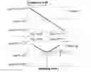
In those cases, the various Fresnel representations of the global signal at the indicated moment of sampling (bit transition) are given on the graph in FIG. 4 (this shows the three previous cases)
In the same way, by envisaging the same bit transitions on the signal 2, but the transitions [bit#n=0/bit#n+1=1] and [bit#n=1/bit#n+1=0] on the signal 1, the corresponding phase and Fresnel diagrams are obtained, as shown in FIGS. 5 and 6.
Thus, for the full set of bit transitions envisaged on the two signals S1 and S2 composing the signal to be demodulated, it is possible to establish a virtually one-to-one correspondence between:
-
- on the one hand, the phase of the global signal at the moment of sampling,
- and, on the other hand, the pair of phase states for each of the signals at the same moment of sampling.
- on the one hand, the phase of the global signal at the moment of sampling,
This is illustrated by the graph in FIG. 7.
-
- 2. The term “virtually one-to-one” is due to the presence of ambiguities in the demodulation process. In the particular case illustrated in FIG. 8, the same value for the phase of the global signal can be associated with two distinct pairs of phase states for each signal component. Such ambiguities occur in the case where the phases of the two component signals are separated by (k.π).
By demodulating according to the Viterbi method, the majority of these ambiguities can be eliminated.
The chosen states of the lattice are then phase state pairs (signals S1 and S2). The successive iterations are then performed as follows:
-
- at each bit transition, the value of the global phase is sampled
- depending on the pairs of preceding phase states (previous level of the
Viterbi lattice), and for each scenario for a received pair of bits, the expected value of the global phase is estimated. This estimated phase is a function of the power difference of the two signals, of the phase states of the signals S1, S2, and also of the values of φoff1 and φoff2.
-
- a metric is then associated with each scenario for a received pair of bits. This metric, which will be used in the execution of the Viterbi algorithm, will have to take account of the difference between the tested scenario and the measured reality. This metric may be defined as the difference between the measured and estimated global phases.
- the bit-stream pair (one for each signal S1 and S2) offering the smallest aggregate metric is then conserved, this aggregate metric being the sum of the aggregate metric calculated in the preceding iteration and the metric calculated in the third step of the current iteration (preceding point).
The method of the invention may also be extended to the cases where the signals are unsynchronized (non-coincident bit transitions), or of different carrier frequencies: the calculation of the global estimated phase then not only takes into account the phase states of the signals S1, S2 and the values of φoff1 and φoff2, but also the phase difference and drift of the signal S2 with respect to S1 (it will be noted that since the synchronization in time and in frequency is carried out on the signal S1, no phase shift nor drift occurs on this signal).
The solution according to the invention has the following advantages. In the case of collisions with two signals, this solution enables a much more effective demodulation of the main signal (the strongest), together with a non-negligible demodulation performance on the “interfering” signal (the weakest). By way of example, in a collision scenario where two signals are simultaneously received, with the same frequency, synchronized (in other words, when received the bit transitions are simultaneous), for a signal S2 which is 5 dB weaker than the signal S1, and beyond 60 dB.Hz signal-to-noise ratio on the signal S1, the likelihood of detection by a simple single-signal demodulator, applied to the two signals S1 and S2 separately, is negligible, whereas the multi-signal demodulation carried out according to the invention allows the demodulation of at least one of the two signals.
Claims
1. A method for demodulating two signals (S1, S2) able to mutually collide, these signals being those of an access system, and on which a time, frequency and phase synchronization has been carried out, the method comprising:
determining the value of the phase of the global signal formed from these two signals, and
determining the values of the phase states of each of these two signals and hence their digital contents using the Viterbi method to eliminate ambiguities produced for cases where the phases of the two signals are separated by kπ, wherein
the Viterbi demodulation, in the case where the two signals include the same carrier frequency and whose bit transitions coincide, comprising the following iterations:
measuring the phase of the global signal sampled at the bit transition times, which will therefore be common to the two signals;
estimating, depending on the pair of phase states (one for each signal S1 and S2) coming from the preceding iteration, and for each scenario for a received pair of bits (one for each signal S1 and S2), the expected value of the global phase, this estimated phase being a function of the differences in power of the two signals, in phase states of the two signals, and also in values of phase difference of these two signals due to different path lengths φoff1 and φoff2);
calculating the metric associated with each scenario for a received bit pair, this metric being the distance between the measured and estimated global phases; and
conserving the bit-stream pair (one for each signal S1 and S2) offering the smallest aggregate metric, this aggregate metric being the sum of the aggregate metric calculated in the preceding iteration and of the metric calculated in the third step of the current iteration.
2. The method according to claim 1, wherein when the bit transitions of the two signals are not coincident when they are received, the successive iterations of the Viterbi method are modified as follows: the phase of the global signal is sampled at the bit transition times of the strongest signal even if the powers are identical, and the calculation of the global phase estimated during each iteration also takes into account the difference in phase of the second signal (S2) with respect to the first signal (S1).
3. The method according to claim 1, wherein the two colliding signals have the same carrier frequency.
4. The method according to claim 1, wherein when the two colliding signals have different carrier frequencies within the same channel, the successive iterations of the Viterbi method are modified as follows: the calculation of the global phase estimated during each iteration also takes into account the drift in phase of the second signal (S2) with respect to the first signal (S1).
5. The method according to claim 1, wherein the characteristics of the signals received and subjected to demodulation follow the specifications associated with multiple-access TDMA, FDMA or CDMA systems.
6. The method according to claim 1, wherein the characteristics of the signals received and subjected to demodulation are linked to the reception conditions Doppler or propagation time.
7. The method according to claim 1, wherein, the method is implemented by a satellite communications system.
8. Equipment implementing the method according to claim 1.
9. Equipment located onboard a satellite implementing the according to claim 1.
10. Equipment integrated into a ground-based mission centre implementing the method according to claim 1.
Images & Drawings included:


Sources:
- United States Patent and Trademark Office - verify current appl. status at the USPTO↗
Recent applications in this class:
- » 20220123970 2022-04-21
RECEIVER FOR RECEIVING A COMBINATION SIGNAL TAKING INTO ACCOUNT INTER-SYMBOL INTERFERENCE, METHOD FOR RECEIVING A COMBINATION SIGNAL, AND COMPUTER PROGRAM - » 20170063578 2017-03-02
Sequence estimation device and method - » 20120155444 2012-06-21
Method for eliminating interference in a receiver, and associated apparatus - » 20120063541 2012-03-15
Method and device for determining estimated values for transmitted symbols in a MIMO-OFDM system - » 20120014482 2012-01-19
Data communication devices, methods, and systems - » 20110268168 2011-11-03
Methods and systems for increased communication throughput - » 20110170637 2011-07-14
Signal separator - » 20100220813 2010-09-02
Protocol operation and message design for SDMA data transmission to a plurality of stations - » 20090323795 2009-12-31
Equalizing structure and equalizing method - » 20090141820 2009-06-04
Apparatus, computer program and method for determining a symbol estimate
Recent applications for this Assignee:
- » 20250173818 2025-05-29
METHOD FOR PERFORMING NON-LOCAL DEMOSAICING OF AN IMAGE, AND ASSOCIATED DEVICE - » 20230058595 2023-02-23
Method for manufacturing a multi-material part by additive manufacturing, using the technique of powder bed selective laser melting or selective laser sintering - » 20220348361 2022-11-03
Ion propulsion device - » 20210181173 2021-06-17
Method and device for measuring atmospheric parameters to estimate the quality of the air and the climate variables - » 20210176103 2021-06-10
Method for demodulating digital signals using multiple digital demodulators - » 20210167477 2021-06-03
Tunable microwave system - » 20210151846 2021-05-20
Microwave waveguide comprising a cavity formed by layers having conductive surfaces and a dielectric strip disposed in the cavity - » 20210135329 2021-05-06
IMPLEMENTATION OF INDUCTIVE POSTS IN AN SIW STRUCTURE AND PRODUCTION OF A GENERIC FILTER - » 20210048537 2021-02-18
Self-assisted fast acquisition and first fix for a standalone GNSS receiver - » 20200395958 2020-12-17
LDPC coding with differentiated protection