Apparatus for longitudinally folding a moving material web twice
US20110281707A1
2011-11-17
13/067,179
2011-05-13
✅ Patent granted
US 8,480,553 B2
2013-07-09
-
-
Hemant M Desai
Oliff & Berridge, PLC
2032-01-17
Abstract:
In order to form two longitudinal folds in a material web, there are two plow folding units which extend in the vertical direction and are arranged behind one another in the movement direction of the material web. Each of the plow folding units has two guide elements for the material web, which guide elements are arranged in the manner of a gable or saddle roof. The guide elements are arranged behind one another in the movement direction of the material web and enclose a folding angle between them. The folding angle between the guide elements of the second plow folding unit which is arranged downstream of the first plow folding unit has a magnitude of at least 100°, preferably of at least 140°.
Assignee:
- HUNKELER AG 22 🇨🇭 Wikon, Switzerland
Applicant:
Interested in similar patents?
Get notified when new applications in this technology area are published.
Classification:
B65H45/08 » CPC main
Folding thin material; Folding limp material without application of pressure to define or form crease lines; Folding webs longitudinally
B65H45/22 » CPC further
Folding thin material; Folding articles or webs with application of pressure to define or form crease lines Longitudinal folders, i.e. for folding moving sheet material parallel to the direction of movement
B65H45/28 » CPC further
Folding thin material; Folding articles or webs with application of pressure to define or form crease lines Folding in combination with cutting
B31F1/00 IPC
Mechanical deformation without removing material, e.g. in combination with laminating
Description
CROSS-REFERENCE TO RELATED APPLICATION
This application claims priority from Swiss Patent Application No. 2010 0755/10, filed May 14, 2010, the entire disclosure of which is incorporated herein by reference.
BACKGROUND
The present invention relates to an apparatus for longitudinally folding a moving material web twice.
BRIEF DESCRIPTION OF THE DRAWINGS
In the following text, one exemplary embodiment of the subject matter of the invention will be explained in greater detail using the drawings, in which, purely diagrammatically:
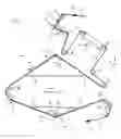
FIG. 1 shows an apparatus for longitudinally folding a moving material web twice, in side view;
FIG. 2 shows a perspective view of one of the plow folding units of the apparatus which is shown in FIG. 1; and
FIG. 3 shows a side view of the web deflecting region of the plow folding unit according to FIG. 2.
DETAILED DESCRIPTION OF EMBODIMENTS
The longitudinal folding apparatus 1 shown in side view in FIG. 1 serves to longitudinally fold a material web 2 twice, which material web 2 is moved through the longitudinal folding apparatus 1 in the direction of the arrows A. The longitudinal folding apparatus 1 has two plow folding units 3 and 4 which are arranged behind one another in the movement direction A of the material web 2. The two plow folding units 3 and 4 are arranged substantially in the direction of the vertical (represented by the arrow V). That is to say, the plow folding units 3 and 4 are arranged at an angle to the horizontal (represented by the arrow H), said angle being 90° in the exemplary embodiment shown. However, said angle can also be less than 90° . In this case, the plow folding units 3, 4 are inclined with respect to the vertical V. The more precise design of the plow folding units 3 and 4, of which each corresponds substantially to the plow folding unit shown in EP-A-2 123 585 (FIGS. 1 and 2), will be explained in greater detail in the following text using FIGS. 2 and 3.
The material web 2 which runs into the longitudinal folding apparatus 1 is first of all guided over a deflecting roller 5 and subsequently runs through a slitting arrangement 6 (shown only diagrammatically) which serves to cut away edge sections of the material web 2. A first drive arrangement 7 for the material web 2 is arranged behind said slitting arrangement 6, which first drive arrangement 7 is followed by a perforating unit 8 which serves to perforate the material web 2 along the future folding lines to be provided. Instead of the perforating unit 8, a scoring unit can also be provided which produces a crease in the material web 2, which crease runs along the folding lines provided. Behind the perforating unit 8, the material web 2 is guided over a number of deflecting rollers, over the deflecting rollers 9, 10, 11, 12, 13 and 14 in the exemplary embodiment which is shown. A web edge controller 16 which is known per se for regulating the run of the material web 2 is arranged between the deflecting rollers 11 and 12. The material web 2 which is deflected around the deflecting roller 14 is folded once in its longitudinal direction in the first plow folding unit 3. The folded material web 2 is then guided over a deflecting arrangement 16 and is driven by means of a second drive arrangement 17 which is arranged between the first plow folding unit 3 and the second plow folding unit 4. The material web 2 is folded a second time in its longitudinal direction in the second plow folding arrangement 4. The material web 2 which has been folded twice is guided around a deflecting roller 18 and is driven by means of a third drive arrangement 19. The material web 2 which has been folded twice is guided around a deflecting roller 20 behind the third drive arrangement 19 and leaves the longitudinal folding apparatus 1 for further processing in the following processing unit.
In the following text, the construction of the plow folding units 3 and 4 will now be described with reference to FIGS. 2 and 3.
The two plow folding units 3, 4 are in principle of identical construction and differ in the exemplary embodiment which is shown only as a result of the magnitude of the folding angle a, as will still be explained. Each plow folding unit 3, 4 has two guide elements 21, 22 or 21′, 22′ (FIG. 1), over which the material web 2 is guided. Each guide element 21, 22 has a folding edge 21a or 22a (FIG. 2) which extends in the movement direction A of the material web 2, but runs obliquely with regard to said movement direction A. The two guide elements 21, 22 or 21′, 22′ are arranged in the manner of a gable or saddle roof behind one another in the movement direction A of the material web 2 and enclose a folding angle a or a1, a2 (FIG. 1) between them. A deflecting element 23 or 23′ (FIG. 1) is arranged at the transition from the first guide element 21 or 21′ to the second guide element 22 or 22′.
As already mentioned, in the exemplary embodiment which is shown, the magnitude of the folding angle a1 between the guide elements 21, 22 of the first plow folding unit 3 differs from the magnitude of the folding angle a2 between the guide elements 21′, 22′ of the other, second plow folding unit 4. Here, the folding angle a1 of the first plow folding unit 3 is smaller than the folding angle a2 of the second plow folding unit 4. In certain cases, the two folding angles a1 and a2 can also be equally large, however. It is important, however, that the folding angle a2 of the second plow folding unit 4 has a minimum magnitude of at least 100°, preferably a minimum magnitude of 140°, in order that the second longitudinal fold can be formed satisfactorily on the material web 2 which has already been folded once.
A passage is provided between the guide elements 21, 22 or 21′, 22′, through which passage that web section of the material web 2 which has been folded over respectively is guided.
The method of operation of the longitudinal folding apparatus 1 is as follows:
The material web 2 is pulled into the longitudinal folding apparatus 1 by means of the first drive arrangement 7 and runs through the slitting arrangement 6 and the perforating unit 8 before it is pulled over the guide elements 21, 22 of the first plow folding unit 3. In said first plow folding unit 3, the formation of the first longitudinal fold in the material web 2 takes place in a manner known per se by folding over a section of the material web 2 along the folding edges 21a, 22a of the guide elements 21, 22. The web tension which is required for the folding operation is produced by the first drive arrangement 7 and the second drive arrangement 17. The material web 2 which has been folded once and is deflected by means of the deflecting arrangement 16 is pulled by the third drive arrangement 19 over the folding elements 21′, 22′ of the second plow folding unit 4, in which the second longitudinal fold is formed in the material web 2 in the way which has already been described. The web tension which is required for this is produced by the second drive arrangement 17 and the third drive arrangement 19. The fact that the folding angle a2 of the second plow folding unit 4 is at least 100°, preferably 140°, ensures that a satisfactory second longitudinal fold is formed in the material web 2 which has already been folded once.
The vertical arrangement of the two plow folding units 3, 4 has the advantage of a space-saving design of the longitudinal folding apparatus 1. If the plow folding units 3, 4 are arranged in such a way that they are inclined with respect to the vertical V, this leads to a larger overall length of the longitudinal folding apparatus 1.
Claims
What is claimed is:1. An apparatus for longitudinally folding a moving material web twice, wherein two plow folding units are provided which are arranged behind one another in the movement direction of the material web, each plow folding unit has two guide elements for the material web, which guide elements are arranged in the manner of a gable or saddle roof, are arranged behind one another in the movement direction of the material web and enclose a folding angle between them, the folding angle between the guide elements of the second plow folding unit which is arranged behind the first plow folding unit having a magnitude of at least 100°.
2. The apparatus as claimed in claim 1, wherein the folding angle between the guide elements of the second plow folding unit has a magnitude of at least 140°.
3. The apparatus as claimed in claim 1, wherein the magnitude of the folding angle between the guide elements of the one, first plow folding unit differs from the magnitude of the folding angle between the guide elements of the other, second plow folding unit.
4. The apparatus as claimed in claim 3, wherein the folding angle between the guide elements of the first plow folding unit is smaller than the folding angle between the guide elements of the second plow folding unit.
5. The apparatus as claimed in claim 1, wherein the guide elements are provided with a folding edge which extends in the movement direction of the material web and runs obliquely with regard to said movement direction.
6. The apparatus as claimed in claim 1, wherein the plow folding units are arranged at an angle to the horizontal, and in that a deflecting arrangement for the material web is provided between the plow folding units.
7. The apparatus as claimed in claim 6, wherein the two plow folding units are arranged substantially vertically.
8. The apparatus as claimed in claim 1, wherein a first drive arrangement for the material web is arranged in front of the first plow folding unit, a second drive arrangement for the material web is arranged between the two plow folding units, and a third drive arrangement for the material web is arranged downstream of the second plow folding unit, a tensile stress being produced in the material web which runs through the first plow folding unit by means of the first and second drive arrangements, and a tensile stress being produced in the material web which runs through the second plow folding unit by means of the second and third drive arrangements.
9. The apparatus as claimed in claim 1, wherein a perforating or scoring unit is arranged in upstream of the first plow folding unit for perforating or scoring the material web along the future folding lines to be provided.
Images & Drawings included:


Sources:
- United States Patent and Trademark Office - verify current appl. status at the USPTO↗
Recent applications in this class:
- » 20200031604 2020-01-30
Conveyor device for a corrugated web, corrugated board manufacturing line including the conveyor device, and method - » 20180194588 2018-07-12
Continuous body folding device and folding method - » 20170203934 2017-07-20
Method and apparatus for pleating or shaping a web - » 20140066279 2014-03-06
FOLDING BLADE FOR A BLOWN FILM LINE AS WELL AS BLOWN FILM LINE WITH SUCH A FOLDING BLADE - » 20140051561 2014-02-20
Assembly and method of folding materials - » 20130303354 2013-11-14
Apparatus and method for folding a web in two - » 20120316047 2012-12-13
DEVICE AND PROCESS FOR FOLDING WEB MATERIALS - » 20100300468 2010-12-02
FILTER TOW BALE, METHOD AND DEVICE FOR PRODUCING A FILTER TOW BALE AND FILTER TOW STRIPS - » 20100292064 2010-11-18
BIAS TAPE MAKER - » 20060280914 2006-12-14
Method and an apparatus for forming an edge thickening along a web material and a web material thus formed
Recent applications for this Assignee:
- » 20250229561 2025-07-17
SORTING DEVICE FOR SORTING BOOK BLOCKS - » 20250206057 2025-06-26
SHEET PROCESSING APPARATUS - » 20170341453 2017-11-30
Method for producing printed products with integrated cover - » 20170197797 2017-07-13
Separator for book blocks - » 20160244291 2016-08-25
Folding apparatus and method - » 20140353958 2014-12-04
Method of, and apparatus for, producing multi-leaf, folded printed products, in particular periodicals and brochures - » 20140306439 2014-10-16
Method for producing printed products consisting of at least three sub-products - » 20140183809 2014-07-03
Method of, and apparatus for, processing sheets of different formats - » 20140183808 2014-07-03
Method of, and apparatus for, processing sheets of different formats - » 20130036884 2013-02-14
METHOD AND APPARATUS FOR PUNCHING OR PERFORATING MOVING MATERIAL WEBS