Method for operating a drive train
US20110282533A1
2011-11-17
13/143,742
2010-01-29
✅ Patent granted
US 8,589,005 B2
2013-11-19
WO; PCT/EP2010/051051; 20100129
WO; WO2010/089246; 20100812
John Q Nguyen | Brian J Broadhead
Davis & Bujold, PLLC | Michael J. Bujold
2030-07-12
Abstract:
A method of operating a drive train of a motor vehicle which includes at least an electric machine, as a drive aggregate, and a transmission which is positioned between the drive aggregate and an output, and a starting element positioned between the electric machine and the transmission. For and during the start, an expected drive resistance is calculated and then, if the expected drive resistance is lower than a first threshold value, starting takes place with the starting element engaged via the electric machine from a standstill, and if the expected drive resistance is larger than the first threshold value, starting takes place with the starting element disengaged, the electric machine is operated with a defined machine rotational speed in a rotation speed control mode, and thereafter, the starting element is engaged such that it transfers starting torque which depends on the a driver request.
Assignee:
- ZF FRIEDRICHSHAFEN AG 3,767 🇩🇪 Friedrichshafen, Germany
Applicant:
Interested in similar patents?
Get notified when new applications in this technology area are published.
Classification:
B60W20/15 » CPC main
Control systems specially adapted for hybrid vehicles; Controlling the power contribution of each of the prime movers to meet required power demand Control strategies specially adapted for achieving a particular effect
B60K6/48 » CPC further
Arrangement or mounting of plural diverse prime-movers for mutual or common propulsion, e.g. hybrid propulsion systems comprising electric motors and internal combustion engines the prime-movers consisting of electric motors and internal combustion engines, e.g. HEVs characterised by the architecture of the hybrid electric vehicle Parallel type
B60L15/2009 » CPC further
Methods, circuits, or devices for controlling the traction-motor speed of electrically-propelled vehicles for control of the vehicle or its driving motor to achieve a desired performance, e.g. speed, torque, programmed variation of speed for braking
B60W10/02 » CPC further
Conjoint control of vehicle sub-units of different type or different function including control of driveline clutches
B60W10/08 » CPC further
Conjoint control of vehicle sub-units of different type or different function including control of propulsion units including control of electric propulsion units, e.g. motors or generators
B60W10/10 » CPC further
Conjoint control of vehicle sub-units of different type or different function including control of change-speed gearings
B60W30/18027 » CPC further
Purposes of road vehicle drive control systems not related to the control of a particular sub-unit, e.g. of systems using conjoint control of vehicle sub-units, or advanced driver assistance systems for ensuring comfort, stability and safety or drive control systems for propelling or retarding the vehicle; Propelling the vehicle related to particular drive situations Drive off, accelerating from standstill
B60L2240/421 » CPC further
Control parameters of input or output; Target parameters; Drive Train control parameters related to electric machines Speed
B60L2240/642 » CPC further
Control parameters of input or output; Target parameters; Navigation input; Road conditions Slope of road
B60W2530/16 » CPC further
Input parameters relating to vehicle conditions or values, not covered by groups or Driving resistance
B60W2552/15 » CPC further
Input parameters relating to infrastructure Road slope
B60W2552/40 » CPC further
Input parameters relating to infrastructure Coefficient of friction
B60W2710/021 » CPC further
Output or target parameters relating to a particular sub-units; Clutches Clutch engagement state
B60W2710/027 » CPC further
Output or target parameters relating to a particular sub-units; Clutches Clutch torque
B60W2710/081 » CPC further
Output or target parameters relating to a particular sub-units; Electric propulsion units Speed
Y02T10/62 » CPC further
Road transport of goods or passengers; Other road transportation technologies with climate change mitigation effect Hybrid vehicles
Y02T10/62 » CPC further
Road transport of goods or passengers; Other road transportation technologies with climate change mitigation effect Hybrid vehicles
Y02T10/64 » CPC further
Road transport of goods or passengers; Other road transportation technologies with climate change mitigation effect Electric machine technologies in electromobility
Y02T10/64 » CPC further
Road transport of goods or passengers; Other road transportation technologies with climate change mitigation effect Electric machine technologies in electromobility
Y02T10/72 » CPC further
Road transport of goods or passengers; Other road transportation technologies with climate change mitigation effect Electric energy management in electromobility
Y02T10/72 » CPC further
Road transport of goods or passengers; Other road transportation technologies with climate change mitigation effect Electric energy management in electromobility
Y02T90/16 » CPC further
Enabling technologies or technologies with a potential or indirect contribution to GHG emissions mitigation; Technologies relating to charging of electric vehicles Information or communication technologies improving the operation of electric vehicles
Y02T90/16 » CPC further
Enabling technologies or technologies with a potential or indirect contribution to GHG emissions mitigation; Technologies relating to charging of electric vehicles Information or communication technologies improving the operation of electric vehicles
B60L15/20 IPC
Methods, circuits, or devices for controlling the traction-motor speed of electrically-propelled vehicles for control of the vehicle or its driving motor to achieve a desired performance, e.g. speed, torque, programmed variation of speed
B60W20/00 » CPC further
Control systems specially adapted for hybrid vehicles
G05D1/00 IPC
Control of position, course or altitude of land, water, air, or space vehicles, e.g. automatic pilot
Description
This application is a National Stage completion of PCT/EP2010/051051 filed Jan. 29, 2010, which claims priority from German patent application serial no. 10 2009 000 720.2 filed Feb. 9, 2009.
FIELD OF THE INVENTION
The invention relates to a method for operating a drive train of a motor vehicle.
BACKGROUND OF THE INVENTION
The main components of a drive train of a motor vehicle are a drive aggregate and a transmission. The transmission changes rotational speed and torque, thus providing a traction force by the drive aggregate to the output of the drive train. The present invention relates to a method for operating a drive train were the drive aggregate comprises at least an electric machine. The inventive method is therefore applicable in a pure electric vehicle, in which the drive aggregate is exclusively an electric machine, as well as for a hybrid vehicle in which the drive aggregate is an electric machine and a combustion engine. The electric machine of the respective drive aggregate is hereby, for instance, designed as a three-phase current synchronous machine.
In a three-phase current synchronous machine, the rotational speed of a rotor corresponds to the rotational speed of a rotating electromagnetic field, thus concluding that the rotor of such a synchronous machine rotates synchronously to the rotating field. A three-phase current synchronous machine, were the rotating field is generated by means of a frequency converter, has therefore no slippage. At that time, when the rotor of the three-phase current synchronous machine is at stand still, mainly just one phase of the synchronous machine has a current flow through it, thus causing a one-sided stress of the related components of the power electronic in the frequency converter. The frequency converter of a three-phase current synchronous machine comprises mainly a rectifier, which represents an interface to a DC intermediate circuit, or DC voltage intermediate circuit, respectively, as well as of an inverter which is fed from this DC intermediate circuit or DC voltage intermediate circuit, respectively.
The inverter comprises switching transistors and generates a pulse width modulated voltage. The inductance of the electric machine creates a smoothing of the current, whereby the amplitude of the resulting output voltage and its frequency can be regulated.
At the time, when a three-phase current synchronous machine is at standstill, its maximal available torque is, for a defined time interval, less than with a rotating synchronous machine, because the components of the power electronics in the frequency converter in a rotating synchronous machine are alternately charged. However, at its stand still, the power electronics are strained one-sided which can cause overheating and thus damage to the power electronics of the frequency converter of the synchronous machine. This causes difficulties during the start of a motor vehicle where the drive aggregate is an electric machine which comprises a three-phase current synchronous machine. Therefore, there exists a need for a method to operate a drive train of a motor vehicle, through which on one hand reliable starting can be realized, and through which on the other hand an overload and thus damage of the electric machine, designed as a three-phase current synchronous machine, can be avoided.
SUMMARY OF THE INVENTION
Based on the above, the present invention addresses the problem to create a novel method for operating a drive train of a motor vehicle.
According to the invention, an expected drive resistance for the start is calculated at the time of the start. If the expected drive resistance is lower than a first threshold value, the start happens with an engaged, transmission external or transmission internal, starting element through the electric machine which is here at a standstill.
At the time, when the expected drive resistance is larger than the first threshold value, initially the electric machine is, with a disengaged, transmission external or transmission internal driving element, operated with a defined machine rotational speed in a rotation speed control mode, and thereafter the transmission external or transmission internal driving element is engaged in a way that it transfers a starting torque which is dependent on the request of the driver.
In accordance with the invention, the method enables safe and reliable starting of a drive train of a motor vehicle were the drive aggregate comprises of an electric machine which is designed as a synchronous machine, specifically as a three-phase current synchronous machine.
During the start, overheating or overloading, respectively, and therefore damage of the power electronics of the electric machine can be avoided.
BRIEF DESCRIPTION OF THE DRAWINGS
One embodiment of the invention, without being limited to it, is further explained through the drawings. These show:
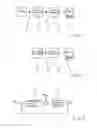
FIG. 1 a schematic drive train of a motor vehicle to which the invented method can be applied to;
FIG. 2 an additional schematic drive train of a motor vehicle to which the invented method can be applied to; and
FIG. 3 a block diagram for the clarification of the aspects of the invented method.
DETAILED DESCRIPTION OF THE PREFERRED EMBODIMENTS
The present invention relates to a method to operate a drive train of a motor vehicle, whereby FIG. 1 and FIG. 2 each show an example of a drive train to which the inventive method can be applied.
Thus, FIG. 1 shows in a simple schematic, a drive train of a so-called parallel hybrid drive, in which the drive train in FIG. 1 comprises a drive aggregate with a combustion engine 1 and an electric machine 2. Between the drive aggregate, that is to say between the electric machine 2 and the output 3, a transmission 4 is positioned, the transmission 4 is preferably designed as an automatic transmission.
In accordance with FIG. 1, a clutch 5 is positioned between the combustion engine 1 and the electric machine 2 of the drive train, in which an additional clutch 6 is positioned between the electric machine 2 and the transmission 4. The clutch 6, between the electric machine 2 and the transmission 4, provides a transmission external starting element. Instead of such transmission external starting element, the drive train of FIG. 1 can also have a transmission internal starting element.
FIG. 2 schematically shows a drive train of a pure electric vehicle, in which the drive aggregate comprises exclusively an electric machine 2, but not a combustion engine. Also in FIG. 2, again between the electric machine 2 and an output 3, a transmission 4 of any design is here positioned, in which again a transmission external starting element 6 is positioned between the electric machine 2 and the transmission 4.
Instead of a transmission external starting element, the drive train as shown in FIG. 2 can also comprise of a transmission internal starting element.
As already presented, the invented method can be applied to a drive train of a hybrid vehicle as in FIG. 1, as well as to the drive train of a pure electric vehicle as in FIG. 2, in which the invention relates to starting of the drive train. The electric machine 2 of the respective drive trains is a synchronous machine, namely a three-phase current synchronous machine.
In terms of the invented method, an expected drive resistance is calculated for the starting of the respective drive train. The expected drive resistance needed to start can be calculated by measurements from slope angle sensors. It is also possible, as an alternative, to calculate the expected drive resistance based on the previous torque results and/or acceleration results of the drive train. Details, through which the drive resistance can be calculated, are known to an expert in the art and do not need to be explained further.
In accordance and in the terms of the present invention, the expected drive resistance for the start, which has been calculated in advance, is now compared to a threshold limit and based on it, the start procedure will be established.
When the expected drive resistance is lower than a first threshold limit, the drive train of FIG. 2 is started from its standstill with the electric machine 2 by engaging the starting element 6. It also applies to the drive train in FIG. 1, whereby in FIG. 1, in addition, the combustion engine 1 is turned off and the clutch 5 positioned between the combustion engine 1 and the electric machine 2 is disengaged.
It is hereby monitored whether the electric machine 2 reaches a minimum rotational speed. If it is determined that this minimum rotation speed has not been reached, the start procedure is terminated and a new start procedure is executed, namely with measurements which can be applied if the prior determined expected drive resistance for the start is larger than the first threshold value.
At the time, when the expected drive resistance is larger than the first threshold value, in reference to the drive train in FIG. 2 and during the start with a disengaged starting element 6, the electric machine 2 is operated with a defined machine rotational speed under rotation speed control mode, whereby the defined machine rotational speed is set above of a minimum rotational speed, at which the electric machine 2 can create a maximum possible torque for a defined time interval. As already mentioned, the electric machine 2 is hereby operated in a rotation speed control mode. Then, after the increase of the machine rotation speed to a defined machine rotational speed, the starting element 6 is engaged in a way such that it can transfer a torque which is desired by the driver. The same applies to the drive train in FIG. 1, whereby the combustion engine 1 in the drive train of FIG. 1 is also turned off and the clutch 5, positioned between the combustion engine 1 and the electrical machine 2, is disengaged.
As previously mentioned and at the time, when the expected drive resistance is larger than the first threshold value, the electric machine 2 is operated in a rotation speed control mode for the starting operation, the structure of the rotational speed control for the electric machine 2 is shown in FIG. 3. During the rotational speed control of the electric machine 2 in the rotation speed control mode, in accordance with FIG. 3, an actual rotational speed NIST of the electric machine 2 is compared to a nominal rotation speed nSOLL and a deviation is executed in a rotational speed control 7, which provides a torque as the control parameter for the electric machine 2.
The torque which is issued by the rotational speed control 7 is combined with a feed forward torque MVOR, whereby the feed forward torque, in the rotation speed control mode, proceeds as the torque of the starting element 6.
In this case, and after the engagement of the starting element 6, the electric machine 2 is switched from the rotation speed control mode to a torque control mode and the starting operation continues with the stating element 6 engaged.
In the case in which the drive train according to FIG. 1 has a combustion engine 1 in an addition to an electric machine 2, the expected drive resistance is compared during the starting operation with two threshold values, namely with the already mentioned first threshold value and a second threshold value which is larger than the first threshold value. In this case, the expected drive resistance is not only larger than the first threshold value, but is also larger than the second threshold value, in the starting operation, with a disengaged starting element 6, the electric machine 2 is operated in the rotation speed control mode with a defined machine rotational speed, and thereafter, the starting element 6 is engaged so that it transfers a starting torque, whereby the combustion engine 1 in addition, by means of the clutch 5 which is operated in slippage mode and which is positioned between the combustion engine 1 and the electric machine 2, transfers an additional starting torque. In this case, the feed forward torque MVOR for the rotational speed control of the electric machine 2 is dependent on the torque of the starting element 6, as well as the torque from the clutch 5 which is positioned between the combustion engine 1 and the electric machine 2. Furthermore, the friction between the clutch 5 and the starting element 6 is split in this case. The clutch 5 has, due to the slippage of the starting element 6, a lower differential rotational speed then when the starting element 6 is completely engaged. The starting element 6 works with a lesser friction than in a situation in which the clutch 5 would be completely engaged.
The starting element 6, however, transfers an identical torque but it also adjusts to a lower differential rotational speed when the clutch 5 slips.
At the time when the expected drive resistance for the drive train, in accordance with FIG. 1, is larger than the first threshold value, but lower than the second threshold value, when the clutch 5 is disengaged and the starting element 6 is disengaged, the electric machine 2 is first brought to a defined machine rotational speed in the rotation speed control mode, and thereafter the starting element 6 is engaged in a way such that it transfers a desired starting torque whereby it is monitored whether the motor vehicle starts after a defined time interval. If it is recognized that the motor vehicle does not start, the start procedure is terminated and a new start procedure is executed with conditions which are applied if the expected drive resistance is larger than the second threshold value.
At the time, when the expected drive resistance for the drive train, in accordance with FIG. 1, is lower than the second threshold value and also lower than the first threshold value, the start from a standstill, as already mentioned, takes place via the electric machine 2 with the combustion engine 1 turned off, the clutch 5 disengaged, and the starting element 6 engaged, whereby it is then monitored whether, after a defined time interval, the electric machine 2 has reached a minimum rotational speed. If it is determined that the electric machine 2 has not reached a minimum rotational speed, the start procedure will be terminated and a new start procedure will be executed, namely either under conditions which can be applied if the expected drive resistance is larger than the first threshold value but lower than the second threshold value, or under conditions which can be applied if the expected drive resistance is larger than the second threshold value.
The invention has a vast number of advantages. A safe start of the motor vehicle can always be realized, i.e., without the danger of an overload and therefore damage to the electric machine, designed as a three-phase current synchronous machine. Furthermore, the maximum available torque of the electric machine 2 can be fully utilized. The starting element, which is designed as a transmission internal or transmission external starting element 6, undergoes just a low load and thus a low wear. If, when starting, the expected drive resistance is larger than the first threshold value, the start only takes place with a slipping transmission internal or transmission external starting element 6. However, if the expected drive resistance is lower than this threshold value, the starting element 6 remains engaged and is therefore not under load.
REFERENCE CHARACTERS
- 1 Combustion Engine
- 2 Electric Machine
- 3 Output
- 4 Transmission
- 5 Clutch
- 6 Starting Element
- 7 Rotational Speed Control
Claims
1-8. (canceled)
9. A method of operating a drive train of a motor vehicle, the drive train comprising at least an electric machine (2) as a drive aggregate, and a transmission (4) that is positioned between the drive aggregate and an output (3), a starting element (6) that is one of external and internal of the transmission (4) and positioned between the electric machine (2) and the transmission (4), the method comprising the steps of:
calculating an expected drive resistance for starting during a starting procedure;
if the expected drive resistance is lower than a first threshold value, carrying out the starting procedure, from a standstill, with the starting element (6) engaged via the electric machine (2); and
if the expected drive resistance is larger than the first threshold value, carrying out the starting procedure with the starting element (6) disengaged and operating the electric machine (2), in a rotation speed control mode, at a defined machine rotation speed and, thereafter, engaging the starting element (6) such that the starting element (6) transfers a starting torque which depends on a request of a driver.
10. The method according to claim 9, further comprising the step of monitoring whether, after a defined time interval, the electric machine (2) reaches a minimum rotation speed, when the expected drive resistance is lower than the first threshold value, and the starting procedure is carried out with the starting element (6) engaged via the electric machine (2) from a standstill, and when the minimum rotation speed is not reached, the start procedure is terminated and a new start procedure is executed under conditions which are applied if the expected drive resistance is larger than the first threshold value.
11. The method according to claim 9, further comprising the step of carrying out the start starting procedure with the electric machine (2) in the rotation speed control mode, when the expected drive resistance is larger than the first threshold value, in which the torque of the starting element (6) determines a forward feed torque for the rotation speed control mode.
12. The method according to claim 9, further comprising the step of switching the electric machine (2) from the rotation speed control mode to a torque control mode, when the expected drive resistance is larger than the first threshold value and after the starting element (6) engages.
13. The method according to claim 9, further comprising the step of carrying out the starting procedure with the starting element (6) disengaged, when the drive aggregate comprises a combustion engine (1) in addition to the electric machine (2) and the expected drive resistance is larger than a second threshold value which is larger than the first threshold value, by operating the electric machine (2) at the defined machine rotation speed in the rotation speed control mode, and, thereafter, the starting element (6) is engaged such that the starting element (6) transfers a starting torque, the combustion engine (1) transferring an additional starting torque of a clutch (5) which is operated in slippage mode and which is positioned between the combustion engine (1) and the electric machine (2).
14. The method according to claim 13, further comprising the step of carrying out the starting procedure, when the expected drive resistance is larger than the second threshold value, and operating the electric machine (2) in the rotation speed control mode, the torque of the starting element (6) and the torque of the clutch (5), which is positioned between the combustion engine (1) and the electric machine (2), determines a forward feed torque for the rotation speed control mode.
15. The method according to claim 13, further comprising the step of operating the electric machine (2) in a defined machine rotation speed in the rotation speed control mode, when the expected drive resistance is larger than the first threshold value and lower than the second threshold value, and with the combustion engine (1) turned off, the clutch (5), which is positioned between the combustion engine (1) and the electric machine (2), is disengaged, and the starting element (6) disengaged, and thereafter, engaging the starting element (6) in a way such that the starting element (6) transfers the start torque, monitoring whether the motor vehicle starts after a defined time interval, and then, if it is determined that the motor vehicle does not start, the start procedure is terminated and a new start procedure is executed with conditions which are applied when the expected drive resistance is larger than the second threshold value.
16. The method according to claim 13, further comprising the step of carrying out the starting procedure when the expected drive resistance is lower than the first threshold value, with the combustion engine (1) turned off, through the clutch (5) which is positioned between the combustion engine (1) and the electric machine (2), and the starting element (6) engaged, via the electric machine (2) from a standstill, and monitoring whether the electric machine (2) reaches a minimum rotation speed after a defined time interval, then terminating the start procedure and executing a new start procedure under the conditions which are applied either when the expected drive resistance is larger than the first threshold value, but lower than the second threshold value, or if the expected drive resistance is larger than the second threshold value.
Images & Drawings included:

Sources:
- United States Patent and Trademark Office - verify current appl. status at the USPTO↗
Similar patent applications:
- » 20160061674
Magnetoelastic torque sensor system for drive train, drive train, method of measuring torque in a drive train, method of operating a drive train and method of manufacturing a primary sensor unit - » 20240270308
ELECTRICALLY OPERABLE AXLE DRIVE TRAIN, METHOD FOR OPERATING AN ELECTRICALLY OPERABLE AXLE DRIVE TRAIN, COMPUTER PROGRAM PRODUCT AND CONTROL UNIT - » 20180202548
VEHICLE DRIVE TRAIN AND METHOD FOR OPERATING A DRIVE TRAIN - » 20200112281
Drive Train and Method for Operating a Drive Train - » 20140190309
Motor vehicle drive train and method of operating a drive train - » 20160236561
DRIVE TRAIN AND METHOD FOR OPERATING A DRIVE TRAIN - » 20120129638
Drive train and method for operating the drive train - » 20170343082
Drive train and method for operating a drive train - » 20190241057
Drive train and method for operating a drive train - » 20090321153
Drive train for a motor vehicle and method of operating a drive train of a motor vehicle
Recent applications in this class:
- » 20250289409 2025-09-18
SYSTEM FOR SETTING A VEHICLE SPEED TRAJECTORY IN RESPONSE TO ENERGY CONSUMPTION - » 20250276681 2025-09-04
VEHICLE CONTROL APPARATUS AND METHOD THEREOF - » 20250269835 2025-08-28
SYSTEM AND METHOD FOR LUBRICATION MANAGEMENT INCLUDING OPERATING POPPET VALVE IN ELECTRIC DRIVE MODULE - » 20250263064 2025-08-21
HYBRID VEHICLE - » 20250263063 2025-08-21
SYSTEM AND METHOD FOR POWER ALLOCATION TO HIGH-VOLTAGE THERMAL LOADS FROM MULTIPLE ENERGY SOURCES IN A HYBRID POWERTRAIN DURING COLD CONDITIONS - » 20250242794 2025-07-31
POWERTRAIN, A METHOD FOR CONTROLLING A POWERTRAIN, AND A VEHICLE - » 20250242793 2025-07-31
STABILIZATION FACTORS AND APPROACHES IN REAL-TIME VEHICLE POWERTRAIN MODE OPTIMIZATION - » 20250236281 2025-07-24
CONTROLLER - » 20250236280 2025-07-24
HYBRID ELECTRIC VEHICLE - » 20250229765 2025-07-17
APPARATUS FOR CONTROLLING DRIVING SYSTEMS OF HYBRID VEHICLE, DRIVING SYSTEM CONTROL METHOD THEREOF, AND SYSTEM INCLUDING THE SAME
Recent applications for this Assignee:
- » 20250293169 2025-09-18
STACKABLE POWER SEMICONDUCTOR MODULE - » 20250292970 2025-09-18
CAPACITIVE WINDING OF A DC LINK CAPACITOR AND DC LINK CAPACITOR WITH A COMMON-MODE CURRENT LEAKAGE FUNCTION - » 20250286013 2025-09-11
APPARATUS AND METHOD FOR MANUFACTURING A POWER SEMICONDUCTOR DEVICE - » 20250283529 2025-09-11
DRIVE UNIT FOR A VEHICLE - » 20250282215 2025-09-11
MOTOR VEHICLE TRANSMISSION FOR AN AT LEAST PARTIALLY ELECTRICALLY DRIVEN MOTOR VEHICLE - » 20250282209 2025-09-11
DRIVE UNIT FOR A VEHICLE - » 20250269709 2025-08-28
ARTICULATED RIGID AXLE OF A VEHICLE WITH AN AXLE SUPPORT WITH AN ELECTRIC MACHINE AS DRIVE - » 20250262892 2025-08-21
AXLE SUPPORT SYSTEM FOR A VEHICLE AXLE - » 20250256806 2025-08-14
BATTERY TERMINAL FOR TWO-WHEELED VEHICLES HAVING AN ELECTRIC DRIVE UNIT - » 20250251033 2025-08-07
GEARBOX AND DRIVE UNIT WITH SUCH A GEARBOX