Left and right interchanging device for a lock clutch
US20110283757A1
2011-11-24
13/198,248
2011-08-04
✅ Patent granted
US 8,910,765 B2
2014-12-16
-
-
Gene Crawford | Mark Manley
Jacobson Holman Hershkovitz, PLLC.
2033-04-19
Abstract:
A left and right interchanging device for a lock clutch includes a clutch pin, an inner rotary clutch shaft, and an outer rotary clutch shaft. The clutch pin is movably placed in a hole of the inner rotary clutch shaft and connected with a built-in driving module of the inner rotary clutch shaft. The module controls the clutch pin so that the clutch pin can retract into or extend out of the inner rotary clutch shaft. The inner rotary clutch shaft is placed in a central hole of the outer rotary clutch shaft, and both can rotate about a same central axis. A first stop edge and a second stop edge are provided on the inner rotary clutch shaft and connected with a driving output shaft. A third stop edge and a fourth stop edge are provided on the outer rotary clutch shaft and connected with a driving output and input shaft. When a door is left-opened, the third stop edge correspondingly contacts the clutch pin and the fourth stop edge correspondingly contacts the second stop edge. When the door is right-opened, the third stop edge contacts the second stop edge, and the fourth stop edge contacts the clutch pin.
Applicant:
Interested in similar patents?
Get notified when new applications in this technology area are published.
Classification:
Y10T70/5805 » CPC further
Locks; Special application; For control and machine elements; Handle, handwheel or knob; Rotary or swinging Freely movable when locked
Y10T70/5832 » CPC further
Locks; Special application; For control and machine elements; Handle, handwheel or knob Lock and handle assembly
Y10T70/7102 » CPC further
Locks; Operating mechanism; Using a powered device [e.g., motor]; Electrical type [e.g., solenoid] And details of blocking system [e.g., linkage, latch, pawl, spring]
Y10T70/8865 » CPC further
Locks; Parts, attachments, accessories and adjuncts Reversible structures
E05B47/0692 » CPC further
Operating or controlling locks or other fastening devices by electric or magnetic means; Controlling mechanically-operated bolts by electro-magnetically-operated detents by disconnecting the handle radially with a rectilinearly moveable coupling element
E05B63/04 » CPC main
Locks or fastenings with special structural characteristics for alternative use on the right-hand or left-hand side of wings
F16D11/16 IPC
Clutches in which the members have interengaging parts with clutching members movable otherwise than only axially
E05B47/02 IPC
Operating or controlling locks or other fastening devices by electric or magnetic means Adaptation of locks, latches, or parts thereof, for movement of the bolt by electromagnetic means
E05B47/06 IPC
Operating or controlling locks or other fastening devices by electric or magnetic means Controlling mechanically-operated bolts by electro-magnetically-operated detents
Description
This application is a continuation-in-part of PCT/CN09/076213, filed Dec. 31, 2009, which has a priority of Chinese Application No. 200920130106.8, filed Feb. 6, 2009, hereby incorporated in its entirety by reference.
FIELD OF THE INVENTION
The present invention involves a part for locks, in particular a left and right interchanging device for a lock clutch.
BACKGROUND OF THE INVENTION
Currently, there are diversified clutch devices for locks.
SUMMARY OF THE INVENTION
The present invention provides a left and right interchanging device for a lock clutch by applying a simple mechanical structure. The simple structure is easy to use and is produced at low cost.
These and other objects of the invention, as well as many of the intended advantages thereof, will become more readily apparent when reference is made to the following description taken in conjunction with the accompanying drawings.
BRIEF DESCRIPTION OF THE DRAWINGS
The following drawings illustrate examples of various components of the invention disclosed herein, and are for illustrative purposes only. Other embodiments that are substantially similar can use other components that have a different appearance.
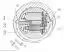
FIG. 1 is a sectional view of forward and backward rotation when a door is left-opened.
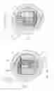
FIG. 2 is a sectional view of forward and backward rotation when a door is right-opened.
FIG. 3 is a sectional view of forward rotation when a door is right-opened and a fourth stop edge 32 contacts a clutch pin 1.
FIG. 4 is a sectional view of backward rotation when a door is right-opened and a fourth stop edge 32 does not contact the clutch pin 1.
FIG. 5 is a sectional view of backward rotation when a door is right-opened.
FIG. 6 is a sectional view of forward rotation when a door is left-opened and a third stop edge 31 contacts the clutch pin 1.
FIG. 7 is a sectional view of forward rotation when a door is left-opened and a third stop edge 31 does not contact the clutch pin 1.
FIG. 8 is a sectional view of backward rotation when a door is left-opened.
In the figures the elements are identified as follows: clutch pin 1; rotary clutch shaft 2; rotary clutch shaft 3; hole 21; driving module 22; first stop edge 23; second stop edge 24; third stop edge 31; and fourth stop edge 32.
DETAILED DESCRIPTION OF THE PREFERRED EMBODIMENTS
In describing a preferred embodiment of the invention illustrated in the drawings, specific terminology will be resorted to for the sake of clarity. However, the invention is not intended to be limited to the specific terms so selected, and it is to be understood that each specific term includes all technical equivalents which operate in a similar manner to accomplish a similar purpose.
A left and right interchanging device for a lock clutch includes a clutch pin 1, a rotary clutch shaft 2, and a hollow rotary clutch shaft 3. The clutch pin 1 is movably placed in a hole 21 of the rotary clutch shaft 2, and connected with a built-in driving module 22 of the rotary clutch shaft 2. The module 22 controls the clutch pin 1, so that the clutch pin 1 can retract into or extend out of the rotary clutch shaft 2. The rotary clutch shaft 2 is placed in a central hole of the rotary clutch shaft 3, and both can rotate about a common central axis.
A first stop edge 23 and a second stop edge 24 are provided on the rotary clutch shaft 2. A third stop edge 31 and a fourth stop edge 32 are provided on the rotary clutch shaft 3. When a door is left-opened, the fourth stop edge 32 contacts the second stop edge 24. When the door is right-opened, the third stop edge 31 contacts the first stop edge 23.
As shown in FIG. 3: right-opened and rotated forward. The rotary clutch shaft 3 rotates forward in a limit stroke. When the clutch pin 1 extends out of the rotary clutch shaft 2, the clutch pin contacts the fourth stop edge 32 of the rotary clutch shaft 3. The rotary clutch shaft 3 rotates to drive the rotary clutch shaft 2, rotating forward together, so that the door is opened.
As shown in FIG. 4: right-opened and rotated forward. When the clutch pin 1 retracts into the rotary clutch shaft 2, the clutch pin does not contact the fourth stop edge 32 of the rotary clutch shaft 3. When the rotary clutch shaft 3 rotates clockwise, the rotary clutch shaft 3 does not contact the rotary clutch shaft 2 through the clutch pin 1 so that the door is locked (FIG. 4).
As shown in FIG. 5: right-opened and rotated backward. The rotary clutch shaft 3 rotates backward in a limit stroke. Whether the clutch pin 1 extends out of the rotary clutch shaft 2 or not, the clutch pin 1 cannot contact the fourth stop edge 32, but the first stop edge 23 of the rotary clutch shaft 2 is contacted by the third stop edge 31 of the rotary clutch shaft 3. The rotary clutch shaft 3 rotates to drive the rotary clutch shaft 2 rotating backward, so that the door is reversely locked.
As shown in FIG. 6: left-opened and rotated forward. The rotary clutch shaft 3 rotates forward in the limit stroke. When the clutch pin 1 extends out of the rotary clutch shaft 2, the clutch pin contacts the third stop edge 31 of the rotary clutch shaft 3. The rotary clutch shaft 3 rotates to drive the rotary clutch shaft 2 rotating forward together, so that the door is opened.
As shown in FIG. 7, when the clutch pin 1 retracts into the rotary clutch shaft 2, the clutch pin 1 does not contact the third stop edge 31 of the rotary clutch shaft 3. The rotary clutch shaft 3 cannot rotate to drive the rotary clutch shaft 2 through the clutch pin 1. The rotary clutch shaft 3 rotates independently, so that the door is locked.
As shown in FIG. 8: left-opened and rotated backward. The rotary clutch shaft 3 rotates backward in the limit stroke. Whether the clutch pin 1 extends out of the rotary clutch shaft 2 or not, the clutch pin cannot contact the third stop edge 31, but the second stop edge 24 of the rotary clutch shaft 2 contacts the fourth stop edge 32 of the rotary clutch shaft 3. The rotary clutch shaft 3 rotates to drive the rotary clutch shaft 2 rotating backward, so that the door is locked reversely.
As shown in FIG. 2: When a door is right-opened, the fourth stop edge 32 correspondingly contacts the clutch pin 1, and the third stop edge 31 correspondingly contacts the first stop edge 23.
As shown in FIG. 1: When a door is left-opened, the fourth stop edge 32 correspondingly contacts the second stop edge 24, and the third stop edge 31 correspondingly contacts the clutch pin 1.
Interchange from left-opened to right-opened: The clutch pin 1 retracts into the rotary clutch shaft 2. When the rotary clutch shaft 2 rotates backward 180 degrees as shown in FIG. 2 (right-opened), the fourth stop edge 32 will contact the second stop edge 24, and the third stop edge 31 does not contact the first stop edge 23, so that right-opened is changed to left-opened.
The foregoing description should be considered as illustrative only of the principles of the invention. Since numerous modifications and changes will readily occur to those skilled in the art, it is not desired to limit the invention to the exact construction and operation shown and described, and, accordingly, all suitable modifications and equivalents may be resorted to, falling within the scope of the invention.
Claims
I claim:1. A left and right interchanging device for a lock clutch, said interchanging device comprising
a clutch pin,
an inner rotary clutch shaft, and
an outer rotary clutch shaft,
the clutch pin being movably placed in a hole of the inner rotary clutch shaft, and connected with a built-in driving module of the inner rotary clutch shaft, the driving module controlling the clutch pin so that the clutch pin retracts into or extends out of the inner rotary clutch shaft, the inner rotary clutch shaft being located in a central hole of the outer rotary clutch shaft, and both the inner rotary clutch shaft and the outer rotary clutch shaft being rotated about a common central shaft axis.
2. The left and right interchanging device for a lock clutch according to claim 1, wherein a first stop edge and a second stop edge are provided on the inner rotary clutch shaft and connected with a driving output shaft, a third stop edge and a fourth stop edge are provided on the outer rotary clutch shaft and connected with a driving input shaft so that when a door is left-opened, the third stop edge correspondingly contacts the clutch pin, and the fourth stop edge correspondingly contacts the second stop edge and when the door is right-opened, the third stop edge contacts the first stop edge and the fourth stop edge contacts the clutch pin.
Images & Drawings included:


Sources:
- United States Patent and Trademark Office - verify current appl. status at the USPTO↗
Recent applications in this class:
- » 20230366240 2023-11-16
Electronic lock compatible with left and right opening and a method for automatically judging left and right opening of the electronic lock - » 20230151642 2023-05-18
Bi-directional electronic lock device and method for setting up the same when mounted on a door - » 20220081938 2022-03-17
Door handing assembly for electromechanical locks - » 20220042350 2022-02-10
SIMPLIFIED LEVER HANDING APPARATUS - » 20180340354 2018-11-29
Door handing assembly for electromechanical locks - » 20180030760 2018-02-01
Simplified lever handing apparatus - » 20170370127 2017-12-28
Method for automatically setting an electronic lock according to a right hand or a left hand installation - » 20170268259 2017-09-21
Lock for left or right hand operation - » 20150308157 2015-10-29
Method for correctly mounting an electronic door lock on a left-handed or right-handed door - » 20150240530 2015-08-27
Simplified lever handing apparatus