Traction battery with increased reliability
US20110285351A1
2011-11-24
13/138,375
2009-12-14
✅ Patent granted
US 8,912,757 B2
2014-12-16
WO; PCT/EP2009/067084; 20091214
WO; WO2010/088999; 20100812
Arun Williams
Maginot, Moore & Beck LLP
2031-10-11
Abstract:
The invention relates to a traction battery having at least two serially connected battery modules, each of which has a first battery module pole, a second battery module pole, and at least one inserted series circuit and/or parallel circuit of battery cells. A first terminal of the series circuit of battery modules is connected to a first battery pole, while a second terminal of the series circuit of battery modules is connected to a second battery pole. According to the invention, at least one battery module of the at least two serially connected battery modules is a first battery module which has at least one disconnecting device and a bridging device. When triggered accordingly, the at least one disconnecting device interrupts the connection between the series circuit and/or parallel circuit of battery cells and the first battery module pole and/or the second battery module pole and/or interrupts the series circuit and/or parallel circuit of battery cells. Furthermore, the first battery module pole and the second battery module pole are short-circuited via the bridging device inserted between the first battery module pole and the second battery module pole when the bridging device is triggered accordingly. Additionally or alternatively, at least one battery module of the at least two serially connected battery modules is a second battery module that has at least one charging and disconnecting device and a bridging device. When triggered accordingly, the at least one charging and disconnecting device interrupts the connection between the series circuit and/or parallel circuit of battery cells and the first battery module pole and/or the second battery module pole and/or interrupts the series circuit and/or parallel circuit of battery cells and limits charging or compensating currents occurring when the battery module or the battery comprising the battery module is connected. Furthermore, the first battery module pole and the second battery module pole are short-circuited via the bridging device inserted between the first battery module pole and the second battery module pole when the bridging device is triggered accordingly.
Assignee:
- Robert Bosch GMBH 19,123 🇩🇪 Stuttgart, Germany
Applicant:
Interested in similar patents?
Get notified when new applications in this technology area are published.
Classification:
H01M10/441 » CPC further
Secondary cells; Manufacture thereof; Methods or arrangements for servicing or maintenance of secondary cells or secondary half-cells; Methods for charging or discharging for several batteries or cells simultaneously or sequentially
H02J7/00 IPC
Circuit arrangements for charging or depolarising batteries or for supplying loads from batteries
H01M10/44 » CPC main
Secondary cells; Manufacture thereof; Methods or arrangements for servicing or maintenance of secondary cells or secondary half-cells Methods for charging or discharging
H01M10/46 » CPC further
Secondary cells; Manufacture thereof; Methods or arrangements for servicing or maintenance of secondary cells or secondary half-cells Accumulators structurally combined with charging apparatus
Y02E60/10 » CPC further
Enabling technologies; Technologies with a potential or indirect contribution to GHG emissions mitigation Energy storage using batteries
Y02E60/10 » CPC further
Enabling technologies; Technologies with a potential or indirect contribution to GHG emissions mitigation Energy storage using batteries
H02J7/0031 » CPC further
Circuit arrangements for charging or depolarising batteries or for supplying loads from batteries with safety or protection devices or circuits using battery or load disconnect circuits
Description
PRIOR ART
The present invention relates to a battery, in particular a traction battery, as described in the preamble to claim 1.
It has become apparent that in the future, both in stationary applications (e.g. wind power stations) and in vehicles (e.g. in hybrid and electric vehicles), there will be increased use of new battery systems that will be subjected to very strict requirements with regard to reliability. The reason for these strict requirements is that a failure of the battery can result in a failure of the overall system (e.g. in an electric vehicle, a failure of the traction battery results in a so-called “stranded vehicle”) or even in a safety-related problem (in wind power stations, for example, batteries are used for adjusting the rotor blades so as to protect the system from impermissible operating states).
The schematic wiring diagram of a battery system according to the current prior art is shown in FIG. 9. To achieve the required performance and energy data with the battery system, individual battery cells are connected in series and partially also in parallel. In addition to the battery cells, the battery system also has a so-called charging and disconnecting device that is shown in FIG. 9 as being situated between the plus pole of the battery and the battery cells, without limiting general design freedom. The circuit breaker TS can be used to switch the battery on and off in monopolar fashion. As an optional functional unit, FIG. 9 shows another disconnecting device with which the battery—if necessary by means of another circuit breaker—can be switched off in bipolar fashion. In the charging and disconnecting device, there is also a so-called charging switch with which a charging resistance can be connected between the battery cells and the externally connected systems in order to limit the equalizing currents when switching on the battery. In such a switching-on procedure, if the circuit breaker is open, then the charging switch in the charging and disconnecting device is first closed and also—if provided—the circuit breaker in the optional disconnecting device on the minus pole of the battery system is closed. Then the input capacitances of the externally connected systems are charged via the charging resistance. If the voltage between the plus pole and minus pole of the battery system deviates only insignificantly from the sum voltage of the battery cells, then the charging procedure is terminated by the closing of the disconnecting switch in the charging and disconnecting device. The battery system is then connected to the external systems in a low-impedance fashion and can be operated with its specified performance data. With the above-explained procedure, the equalizing currents that occur between the external systems and the battery system at the switching-on of the battery system can be limited to permissible values.
The reliability of the battery system is indicated by the failure rate. The failure rate describes the number of failures to be expected on average in a given period of time.
The failure rate of a battery with a series circuit of individual cells can be determined as follows:
Failure ratetraction battery=1−(1−failure ratecell)number of cells (1)
The traction battery of an electric vehicle with a series circuit of 100 cells and a failure rate of 100 ppm/cell in the given period of time, for example, thus yields the following:
Failure rate traction battery = 1 - ( 1 - 100 ppm ) 100 = 9.95 % 0 ( 2 )
With very low failure rates of the individual battery cells (e.g. failure ratecell<10/00 in the given time period), the failure rate can be calculated approximately as follows (the power series expansion of the binomial series interrupted after the first term):
Failure ratetraction battery≈number of cells*failure ratecell (3)
The failure rate of the traction battery in question is therefore about 100 times greater than the failure rate of an individual cell. The failure rate of the individual cells must therefore be smaller by a factor of approximately 100, given the required values for the failure rate of the battery system. For a battery system with 100 series connected cells, if a failure rate of 100 ppm in the given period of time is required, then the cells must have a failure rate of 1 ppm during this period of time. This is a requirement that is extremely hard to fulfill.
The object of the invention is to increase the reliability of battery systems in comparison to the current prior art. With the invention, the failure of one or more cells of a battery module should not result in the complete failure of the battery system. The battery system should then still be available with limited power.
DISCLOSURE OF THE INVENTION
The battery according to the invention, with the defining characteristics of claim 1, has the advantage over the prior art that the battery system is internally modified relative to the current prior art by adding functional units. These additional functional units include
disconnecting devices and/or
charging and disconnecting devices and/or
bridging devices
that will be described in greater detail below. These functional units have been used according to the invention to construct battery modules that can be bridged over upon failure of one or more cells. If the overall system is composed of a plurality of such battery modules, then—depending on the requirements and the embodiment of the battery system—one or more of the battery modules can be bridged over upon failure of one or more cells in the corresponding module. The battery system does then have a limited power at its terminals as compared to regular operation, but with a suitable design of the battery system, it is possible to prevent the system from failing or shifting into a safety-critical state. In addition, the failure of the cells or module is detected and repair procedures can be initiated. This increases the reliability of the battery system.
Preferred modifications of the invention are disclosed in the dependent claims.
In a particularly preferred embodiment, the battery according to the invention includes a charging device that is connected between the first terminal of the series circuit of battery modules and the first battery pole and/or is connected between the second terminal of the series circuit of battery modules and the second battery pole, with the battery including only first battery modules. In this case, in the event of a failure of any of the battery modules, a limiting of the equalizing currents in the traction electrical system is assured; only simply designed first battery modules are provided.
In an alternative embodiment, the battery according to the invention preferably includes only second battery modules. In this case, even if any of the battery modules fails, a limiting of the equalizing currents in the traction electrical system takes place; it is not necessary to provide a separate charging device since the second battery modules are each equipped with one. This permits a simpler assembly of the battery, which is composed exclusively of identical modules.
In an alternative embodiment, the battery according to the invention preferably includes n battery modules: 2 second battery modules and n−2 first battery modules. In this case, even if one of the second battery modules fails, a limiting of the equalizing currents in the traction electrical system is assured since in this case, the charging device of the second of the second battery modules is still present and can be used.
In the battery according to the invention, the bridging device is preferably also embodied or alternatively embodied so that it can produce a short-circuit of the first battery module pole and second battery module pole only if there is an interruption of the connection between the series circuit and/or parallel circuit of battery cells and the first battery module pole and/or an interruption of the connection between the series circuit and/or parallel circuit of battery cells and the second battery module pole and/or an interruption of the series circuit and/or parallel circuit of battery cells.
DRAWINGS
An exemplary embodiment of the invention will be described in detail below with reference to the accompanying drawings.
FIG. 1 shows a schematic wiring diagram of a battery, preferably a traction battery, according to a first preferred embodiment of the invention,
FIG. 2 shows a schematic wiring diagram of a battery, preferably a traction battery, according to a second preferred embodiment of the invention,
FIG. 3 shows a schematic wiring diagram of a battery, preferably a traction battery, according to a third preferred embodiment of the invention,
FIG. 4 shows a schematic wiring diagram of a first battery module according to a preferred embodiment of the invention,
FIG. 5 shows a schematic wiring diagram of a second battery module according to a preferred embodiment of the invention,
FIG. 6 shows a schematic wiring diagram of a disconnecting device according to a preferred embodiment of the invention,
FIG. 7 shows a schematic wiring diagram of a charging and disconnecting device according to a preferred embodiment of the invention,
FIG. 8 shows a schematic wiring diagram of a bridging device according to a preferred embodiment of the invention, and
FIG. 9 shows a schematic wiring diagram of a traction battery according to the prior art.
PREFERRED EMBODIMENTS OF THE INVENTION
Preferred embodiments of the invention will be described in detail below with reference to the drawings.
First, a definition will be given for the term reliability as it is used here (definition according to Laubner/Göhner: Prozessautomatisierung 1 [process automation], 3rd edition, Springer-Verlag):
Reliability is the capacity of a system to function properly for a predetermined time (also referred to as dependability).
The invention increases the reliability of battery systems compared to the prior art because the failure of an individual battery cell does not immediately result in the failure of the battery system. As opposed to the current prior art, with the present invention, in battery modules that have a series circuit of battery cells, the battery system is preferably modified internally by adding functional units that will be first described below:
-
- Disconnecting devices 1d, a schematic depiction of which is shown in FIG. 6a and one embodiment of which is shown in FIG. 6b:
- A disconnecting device 1d is used to disconnect the battery cells 1c of a first battery module 1 in monopolar fashion from one of the two poles 1a, 1b of the battery module 1 and to connect the battery cells 1c in a low-impedance fashion to the corresponding pole 1a, 1b.
- For a bipolar disconnection of the battery cells 1c from the two poles 1a, 1b of the battery module 1, it is also possible to use two disconnecting devices 1d in a battery module 1 (it is practical to respectively provide one directly on the plus pole of the battery module and one directly on the minus pole).
- The basic principle of the present invention is independent of the specific embodiment of the circuit breaker TS in the disconnecting device 1d; it can be embodied among other things in the form of an electromechanical switch (relay or contactor), an electronic switch (semiconductor switch), or a combination of an electromechanical and electronic switch.
- Charging and disconnecting devices 2d, a schematic depiction of which is shown in FIG. 7a and one embodiment of which is shown in FIG. 7b:
- A charging and disconnecting device 2d constitutes the functional expansion of a disconnecting device 2d1, which functions in the same way as the disconnecting device 1d described above in connection with FIG. 6 and has the same purpose, through addition of a charging device 2d2, which limits the charging and equalizing currents that occur when the battery system or a battery module is switched on. These currents are caused by the input capacitances of the external systems, which before the battery is switched on, are generally not at the same voltage as the sum voltage of the battery system. In the simplest case, the charging and equalizing currents are limited by means of a resistance LW, which is connected in series with the charging switch LS. Through suitable selection of the resistance value, the equalizing currents are limited to permissible values for the battery system and for the external systems. If the voltage at the poles of the battery system or the voltage at the poles of a battery module 2 equipped with a charging and disconnecting device 2d is approximately the same voltage as the sum voltage of the corresponding battery cells 2c (i.e. the voltage drop at the charging resistance is low), then the circuit breaker TS in the charging and disconnecting device 2d can be closed. The switching-on procedure of a battery system or a battery module therefore occurs as follows: If the circuit breaker TS is open, then the charging switch LS of the charging and disconnecting module 2d is first closed. The external capacitances are then charged or recharged until the voltage at the poles of the battery system or battery module approximately corresponds to the sum voltage of the associated battery cells. Then, the circuit breaker TS is closed and the charging procedure is terminated. The battery cells are then connected in a low-impedance fashion to the poles of the battery system or battery module.
- The circuit breaker TS and the charging switch LS of the charging and disconnecting module 2d can have the same concrete embodiment as the circuit breaker TS of the disconnecting device 1d.
- Bridging devices 1e; 2e, a schematic depiction of which is shown in FIG. 8a and one embodiment of which is shown in FIG. 8b:
- A bridging device 1e; 2e is used to bridge a battery module 1, 2 in low-impedance fashion, i.e. to connect the plus and minus poles of the battery module 1, 2 in low-impedance fashion, upon failure of one or more battery cells 1c, 2c in the battery module 1, 2.
- The basic principle of the present invention is independent of the specific embodiment of the bypass switch US in the bridging device, which—as described in connection with the circuit breaker—can be embodied among other things in the form of an electromechanical switch (relay or contactor), an electronic switch (semiconductor switch), or a combination of an electromechanical and electronic switch.
Battery modules can be constructed based on the above-described functional units and can then be connected to battery systems. Depending on the requirements placed on the battery system, it can be practical to use the following topologies for the battery modules:
-
- First battery module (topology 1) with a disconnecting device and bridging device, as shown in FIG. 4.
- In this topology, a disconnecting device 1d is used to disconnect the battery cells 1c in monopolar fashion from one of the two poles 1a, 1b of the first battery module 1 and to connect the battery cells 1c to the corresponding pole 1a, 1b in a low-impedance fashion. In FIG. 4, the disconnecting device 1d is shown situated on the plus pole 1a, without limiting general design freedom.
- The bridging device 1e, which is arranged in parallel with the disconnecting device 1d and the battery cells 1c, is used to bridge over the first battery module 1 in a low-impedance fashion upon failure of one or more cells 1c of the first battery module 1. The bypass switch in the bridging device 1e is preferably closed only if the circuit breaker in the disconnecting device is open.
- The disconnecting device 1d and the bridging device 1e are triggered via signal lines to control and diagnose the battery module functional units, which are not shown.
- Second battery module (topology 2) with a charging and disconnecting device and a bridging device, as shown in FIG. 5.
- By contrast with topology 1, in this topology, a charging device is additionally provided in the second battery module 2, i.e. a charging and disconnecting device 2d shown in FIG. 7 is used in lieu of the disconnecting device 1d to limit the charging and equalizing currents when the battery system is switched on (other properties equivalent to topology 1).
- The charging and disconnecting device 2d and the bridging device 2e are triggered via signal lines to control and diagnose the battery module functional units, which are not shown.
The above-described battery modules are used according to the invention to construct modular battery systems that have an increased reliability by comparison with the current prior art. Three battery systems with different topologies (labeled topology A, B, and C) should be taken into consideration as examples for the interconnection of the above-described battery modules.
-
- Battery system with topology A according to a second preferred embodiment of the invention, as depicted in FIG. 2, with
- a separate charging and disconnecting device 7,
- several first battery modules 1 (topology 1) connected in series.
- Advantages:
- Uniform battery modules are used.
- All told, only one charging device is used, which is active when the battery system is switched on.
- Battery system with topology B according to a third preferred embodiment of the invention, as depicted in FIG. 3, with
- a plurality of second battery modules 2 (topology 2) connected in series.
- Advantages:
- Uniform battery modules are used.
- Lower internal resistance by comparison with topology A since one fewer disconnecting device is connected in series.
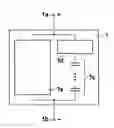
- Battery system with topology C according to a first preferred embodiment of the invention, as depicted in FIG. 1, with
- two second battery modules 2 (topology 2) connected in series,
- one or more first battery modules 1 (topology 1) connected in series.
- Advantages:
- Lower internal resistance by comparison with topology A since one fewer disconnecting device is connected in series.
- Lower additional cost, by comparison with topology B, for the charging devices, which are only provided in two battery modules (cost and space savings). Two battery modules with charging devices are required so that in the event of a malfunction in one of these two modules, after a bridging procedure, there is still one charging device for connecting the battery to the external systems.
- Battery system with topology A according to a second preferred embodiment of the invention, as depicted in FIG. 2, with
The following applies to all of the above-described battery systems:
Upon failure of one or more cells in a battery module, after the disconnecting switch in the disconnecting device(s) is/are opened, the affected module can be short-circuited in a low-impedance fashion by closing the bypass switch.
Depending on the number of battery modules of the battery system and the number of bridged-over battery modules, there is then still a battery system available, which has the following data as compared to the regular operation with all battery modules.
| Battery system with | Bridging of | Bridging of | Bridging of |
| n modules | 1 module | 2 modules | n−1 modules |
| Reduction of power P to | n - 1 n · P Regular | n - 2 n · P Regular | 1 n · P Regular |
| Reduction of Energy E to | n - 1 n · E Regular | n - 2 n · E Regular | 1 n · E Regular |
In a battery system with 5 battery modules, after a battery module is bridged over, a battery system is available that still has 80% of the power and 80% of the energy of the complete battery system.
In addition to the above written disclosure, the disclosure in the figures is also expressly included herein by reference.
Claims
1-5. (canceled)
6. A battery, in particular a traction battery, comprising
at least two series-connected battery modules, each of which has a first battery module pole, a second battery module pole, and at least one series circuit and/or parallel circuit of battery cells connected between them;
a first terminal of the series circuit of battery modules is connected to a first battery pole, while a second terminal of the series circuit of battery modules is connected to a second battery pole, wherein
at least one battery module of the at least two serially connected battery modules is a first battery module, which has at least one disconnecting device and one bridging device;
when triggered accordingly, the at least one disconnecting device interrupts a connection between the series circuit and/or parallel circuit of battery cells and the first battery module pole and/or second battery module pole and/or interrupts the series circuit and/or parallel circuit of battery cells; and
when triggered accordingly, the bridging device, which is connected between the first battery module pole and second battery module pole, short-circuits the first battery module pole and the second battery module pole, and/or
at least one battery module of the at least two series-connected battery modules is a second battery module that has at least one charging and disconnecting device and one bridging device;
when triggered accordingly, the at least one charging and disconnecting device interrupts the connection between the series circuit and/or parallel circuit of battery cells and the first battery module pole and/or second battery module pole and/or interrupts the series circuit and/or parallel circuit of battery cells and limits charging or equalizing currents occurring when the battery module or the battery with the battery module is switched on; and
when triggered accordingly, the bridging device, which is connected between the first battery module pole and second battery module pole, short-circuits the first battery module pole and second battery module pole.
7. The battery according to claim 6, further comprising a charging device, which is connected between the first terminal of the series circuit of battery modules and the first battery pole and/or is connected between the second terminal of the series circuit of battery modules and the second battery pole, with the battery including only first battery modules.
8. The battery according to claim 6, wherein the battery includes only second battery modules.
9. The battery according to claim 6, wherein the battery includes n battery modules: 2 second battery modules and n−2 first battery modules.
10. The battery according to claim 6, wherein the bridging device is embodied so that it is able to produce a short-circuit of the first battery module pole and second battery module pole only if there is an interruption of the connection of the series circuit and/or parallel circuit of battery cells to the first battery module pole and/or an interruption of the connection of the series circuit and/or parallel circuit of battery cells to the second battery module pole and/or an interruption of the series circuit and/or parallel circuit of battery cells.
11. The battery according to claim 7, wherein the bridging device is embodied so that it is able to produce a short-circuit of the first battery module pole and second battery module pole only if there is an interruption of the connection of the series circuit and/or parallel circuit of battery cells to the first battery module pole and/or an interruption of the connection of the series circuit and/or parallel circuit of battery cells to the second battery module pole and/or an interruption of the series circuit and/or parallel circuit of battery cells.
12. The battery according to claim 8, wherein the bridging device is embodied so that it is able to produce a short-circuit of the first battery module pole and second battery module pole only if there is an interruption of the connection of the series circuit and/or parallel circuit of battery cells to the first battery module pole and/or an interruption of the connection of the series circuit and/or parallel circuit of battery cells to the second battery module pole and/or an interruption of the series circuit and/or parallel circuit of battery cells.
13. The battery according to claim 9, wherein the bridging device is embodied so that it is able to produce a short-circuit of the first battery module pole and second battery module pole only if there is an interruption of the connection of the series circuit and/or parallel circuit of battery cells to the first battery module pole and/or an interruption of the connection of the series circuit and/or parallel circuit of battery cells to the second battery module pole and/or an interruption of the series circuit and/or parallel circuit of battery cells.
Images & Drawings included:

Sources:
- United States Patent and Trademark Office - verify current appl. status at the USPTO↗
Similar patent applications:
- » 20110286137
Traction battery having increased reliability
Recent applications in this class:
- » 20250266516 2025-08-21
BATTERY DISCHARGE SYSTEM FOR END-OF-LIFE PROTECTION - » 20250260077 2025-08-14
CHARGING CONTROL METHOD AND APPARATUS, AND ELECTRONIC DEVICE - » 20250183388 2025-06-05
Charging and Discharging Management Method - » 20250174745 2025-05-29
VEHICULAR BATTERY CHARGER, CHARGING SYSTEM, AND METHOD WITH PROGRAMMED CHARGING SESSION OVERRIDE - » 20250167321 2025-05-22
VEHICULAR BATTERY CHARGER, CHARGING SYSTEM, AND METHOD DISPLAYING CHARGE TIME - » 20250167320 2025-05-22
VEHICULAR BATTERY CHARGER, CHARGING SYSTEM, AND METHOD WITH A TIME DELAY FUNCTION - » 20250140951 2025-05-01
SELECTIVE DISABLING OF BATTERIES FROM BATTERY PACK BASED ON PREDICTED LEVEL OF DENDRITE FORMATION - » 20250112285 2025-04-03
METHOD FOR DENDRITE FORMATION SUPPRESSION IN SECONDARY BATTERIES - » 20250046890 2025-02-06
BATTERY MANAGEMENT DEVICE, BATTERY PACK, AND BATTERY PACK CHARGING CONTROL METHOD - » 20250046889 2025-02-06
BATTERY MANAGEMENT SYSTEM AND METHOD FOR CHARGING BATTERY
Recent applications for this Assignee:
- » 20250154889 2025-05-15
PRESSURE CONTROL IN AN EXHAUST AFTERTREATMENT SYSTEM - » 20250154580 2025-05-15
ENZYME TRANSLOCATORS IN NANOGAP WITH 3' -ESTERS - » 20250147582 2025-05-08
METHOD FOR DETERMINING AN EYE DISTANCE IN A PAIR OF DATA GLASSES, AND DATA GLASSES - » 20250146568 2025-05-08
DRIVE ASSEMBLY AND VEHICLE HAVING SUCH A DRIVE ASSEMBLY - » 20250146495 2025-05-08
Flexible Pump Assembly for Use in a Fan Drive - » 20250140882 2025-05-01
FUEL CELL SYSTEM HAVING ENERGY RECUPERATION - » 20250137810 2025-05-01
METHOD FOR MATCHING A DIGITAL ROAD MAP - » 20250137033 2025-05-01
DNA UNFOLDING USING A FREE-END TAG FLOW MODIFIER - » 20250119751 2025-04-10
A BLUETOOTH COMMUNICATION METHOD AND SYSTEM - » 20250118116 2025-04-10
Diagnostic Protocol Search With Improved Efficiency