Apparatus and method for mounting of cabinets
US20110290957A1
2011-12-01
13/118,133
2011-05-27
✅ Patent granted
US 8,439,322 B2
2013-05-14
-
-
Terrell McKinnon | Christopher Garft
Bryan Cave LLP
2031-05-27
Abstract:
A mounting post for supporting a plurality of electronic cabinets, each having different bolt patterns, comprising a hollow post configured to receive a hollow mount at the upper end, a stabilizer plate attached to the lower end of the post, and a hollow mount selected from a plurality of hollow mounts, each having a lower end configured to mate to the post, and having a substantially planar upper surface with openings formed therein corresponding to a unique bolt pattern for an electronics cabinet.
Inventors:
- Michael E. Skudin 1 🇺🇸 Little Rock, AR, United States
- Dennis D. Davis 1 🇺🇸 Sheridan, AR, United States
- David W. Willis 1 🇺🇸 Franklin, IN, United States
Assignee:
- General Devices Co., Inc. 8 🇺🇸 Indianapolis, IN, United States
- Windstream Intellectual Property Services, Inc. 1 🇺🇸 Little Rock, AR, United States
Applicant:
Interested in similar patents?
Get notified when new applications in this technology area are published.
Classification:
A47G23/02 IPC
Other table equipment Glass or bottle holders
E04C3/32 » CPC main
Structural elongated elements designed for load-supporting; Columns; Pillars; Struts of metal
H01Q1/1242 » CPC further
Details of, or arrangements associated with, antennas; Supports; Mounting means Rigid masts specially adapted for supporting an aerial
H01Q1/42 » CPC further
Details of, or arrangements associated with, antennas Housings not intimately mechanically associated with radiating elements, e.g. radome
Y10T29/49826 » CPC further
Metal working; Method of mechanical manufacture Assembling or joining
F16M11/04 IPC
Stands or trestles as supports for apparatus or articles placed thereon Stands for scientific apparatus such as gravitational force meters; Heads Means for attachment of apparatus; Means allowing adjustment of the apparatus relatively to the stand
B23P11/00 IPC
Connecting or disconnecting metal parts or objects by metal-working techniques not otherwise provided for
F16M13/00 IPC
Other supports for positioning apparatus or articles ; Means for steadying hand-held apparatus or articles
A47B96/00 IPC
Details of cabinets, racks or shelf units not covered by a single one of groups - ; General details of furniture
A47B97/00 IPC
Furniture or accessories for furniture, not provided for in other groups of this subclass
A47B91/00 IPC
Feet for furniture in general
A47G29/00 IPC
Supports, holders, or containers for household use, not provided for in groups - or
A47K1/00 IPC
Wash-stands; Appurtenances therefor
A47H1/10 IPC
Curtain suspension devices Means for mounting curtain rods or rails
A47B81/00 IPC
Cabinets or racks specially adapted for other particular purposes, e.g. for storing guns or skis
Description
CROSS-REFERENCE TO RELATED APPLICATIONS
This application claims benefit of priority under 35 U.S.C. Section 119(e) to U.S. Provisional Application Ser. No. 61/350398, filed Jun. 1, 2010, entitled “APPARATUS AND METHODS FOR MOUNTING OF CABINETS,” which is hereby incorporated herein by reference.
BACKGROUND OF THE INVENTION
1. Field of the Invention
The present invention relates generally to exterior mounting of cabinets that house electronic devices commonly used to provide telecommunication services.
2. Description of the Related Art
Conventional methods for exterior mounting of cabinets that house electronic devices commonly used to provide telecommunication services include utility pole with mount kit, pre-cast pads, and site poured pads.
SUMMARY OF THE INVENTION
In accordance with various illustrative embodiments hereinafter described, the present invention is a device that may be used to mount cabinets that house electronic and electrical devices, such as the types commonly used to provide telecommunication services, in an outdoor environment. The present invention minimizes the costs and the depth profile of cabinet installations, while maximizing protection of both the cabinet and the cable associated with that installation. The present invention also comprises a two-piece pole and mount configuration that allows for the use of one of a variety of mounts that are configured to accommodate different electronics cabinet sizes and configurations to be installed on a single post design, thus minimizing manufacturing and inventory costs.
The invention can be used in lieu of utility pole with mount kit, H-Frame mounts, pre-cast pads, and site poured pads. The present invention thus reduces the overall cabinet footprint required when placing cabinet apparatus on right of ways (“ROWs”). The present invention also reduces labor costs and site preparation activities.
The present invention provides a mounting post to raise the electronics cabinet up off the ground, while keeping the overall depth of the total apparatus to a minimum. The present invention raises the electronics cabinet up off the ground by approximately 2 feet, making it easier to work on and less likely to get damaged from ROW mowers. The hollow post design provides for protection of the cabling routed in the interior, and requires less site preparation than other methods, as little to no leveling is required. The elongated slot in the side of the post allows cables to be routed through the post without impingement or abrasion. The top mount design allows for a minimum depth dimension and reduces man-hours and equipment required because the 14″ diameter post will fit into the hole drilled by a standard auger. The top mount design also allows for rear access into the cabinet, whereas traditional pole mount designs limited the types of cabinet configurations.
The stabilizer plate welded to the lower end of the tube provides stability and limits penetration and settling of the post into the soil, while the opening in the stabilizer plate allows for drainage of liquid from the lower end of the tube. The access panel in the transition piece allows for ease of access in routing and installing cables from the post into the electronics cabinet.
The two piece pole and mount configuration allows for a variety of mounts that are configured to accommodate different electronics cabinet sizes and configurations to be installed on a single post design. The hollow mount design permits mating of cable entry openings for a variety of different cabinet configurations by selected use of openings from multiple different cabinet mounting bolt patterns in a single mount configuration.
BRIEF DESCRIPTION OF THE DRAWINGS
The above mentioned and other features and objects of this invention and the manner of attaining them will become more apparent and the invention itself will be better understood by reference to the following description of an embodiment of the invention taken in conjunction with the accompanying drawings.
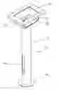
FIG. 1 is an overhead perspective view of the mounting post assembly according to one embodiment of the present invention.
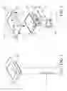
FIG. 2 is an exploded perspective view of the mounting post assembly according to one embodiment of the present invention.
FIG. 3 is an underside perspective view of the mounting post assembly according to one embodiment of the present invention.
FIG. 4 is an underside perspective view of the mounting post assembly according to one embodiment of the present invention as installed in the ground with a commercially available cabinet bolted in place.
DETAILED DESCRIPTION
The one embodiment, the present invention comprises a mounting post assembly configured to accommodate different cabinets. As illustrated in FIG. 1, in one embodiment, the present invention is comprised of two sections; the tubular post 12 and the mounting assembly 22. The post 12 preferably consists of an eight inch diameter aluminum tube that is ¼ inch thick and 64.5 inches in length. There is a ¼inch thick by 14 inch diameter stabilizer plate 16 welded to the lower end of the post 12.
As illustrated in FIG. 2, the post 12 has a mounting flange 20 welded to the upper end. Also as illustrated in FIG. 2, the mounting assembly 22 comprises a transition piece 24, which is preferably a 19.3 by 28.7 inch, 11 gauge platform which is bolted to the mounting flange 20 of tube 12 using flange bolts 36. The transition piece 24 has a front access panel opening 38, which can be fitted with access panel covering 28, which is secured using access panel screws 40. The transition piece 24 is welded to mounting plate 26, which has multiple arrays of bolt openings 30A, 30B, and 30C to accommodate bolt patterns of popular cabinet installation configurations.
As illustrated in FIG. 3, the stabilizer plate 16 welded to the lower end of the tube provides stability and limits penetration and settling of the post 12 into the soil, while the opening 18 in the stabilizer plate allows for drainage of liquid from the lower end of the tube 12. The elongated slot 14 in the side of the post 12 allows cables to be routed through the post 12 and into the mounting assembly 22 without impingement or abrasion.
FIG. 4 illustrates the mounting post assembly according to one embodiment of the present invention as installed in the ground with a commercially available cabinet 42 bolted in place. As illustrated in FIG. 4, the stabilizer plate 16 limits penetration and settling of the post 12 into the soil 44.
The present invention may thus encompass a mounting post for supporting a plurality of electronic cabinets, each having different bolt patterns, comprising a hollow post configured to receive a hollow mount at the upper end, a stabilizer plate attached to the lower end of the post, and a hollow mount selected from a plurality of hollow mounts, each having a lower end configured to mate to the post, and having a substantially planar upper surface with openings formed therein corresponding to a unique bolt pattern for an electronics cabinet.
The present invention may also include a mounting post for supporting a plurality of electronic cabinets, each having different bolt patterns, comprising, a hollow post configured to receive a hollow mount at the upper end, a stabilizer plate attached to the lower end of the post, and a hollow mount having a lower end configured to mate to the post, and having a substantially planar upper surface with openings formed therein corresponding to a plurality of bolt patterns for an electronics cabinet.
Thus, in essence, the present invention comprises a method for supporting a plurality of electronic cabinets, each having different bolt patterns, comprising the steps of providing a hollow post configured to receive a hollow mount at the upper end, attaching stabilizer plate to the lower end of the post, and attaching to the post a hollow mount selected from a plurality of hollow mounts, each having a lower end configured to mate to the post, and having a substantially planar upper surface with openings formed therein corresponding to a unique bolt pattern for an electronics cabinet.
These examples are provided for the purposes of illustration and the present invention is not limited to them. Many changes, modifications, variations, combinations, subcombinations and other uses and applications of the subject invention will be and become apparent to those skilled in the art after considering this specification and the accompanying drawings, which disclose a preferred embodiment thereof. All such changes, modifications, variations, and other uses and applications that do not depart from the spirit and scope of the invention are deemed to be covered by the invention, which is to be limited only by the claims which follow.
Claims
What is claimed is:1. A mounting post for supporting a plurality of electronic cabinets, each having different bolt patterns, comprising:
a hollow post configured to receive a hollow mount at the upper end;
a stabilizer plate attached to the lower end of the post; and
a hollow mount selected from a plurality of hollow mounts, each having a lower end configured to mate to the post, and having a substantially planar upper surface with openings formed therein corresponding to a unique bolt pattern for an electronics cabinet.
2. The mounting post of claim 1, further comprising a removable access panel in the mount.
3. The mounting post of claim 1, further comprising an elongated slot in the post.
4. The mounting post of claim 1, further comprising an opening in the stabilizer plate.
5. A mounting post for supporting a plurality of electronic cabinets, each having different bolt patterns, comprising:
a hollow post configured to receive a hollow mount at the upper end;
a stabilizer plate attached to the lower end of the post; and
a hollow mount having a lower end configured to mate to the post, and having a substantially planar upper surface with openings formed therein corresponding to a plurality of bolt patterns for an electronics cabinet.
6. The mounting post of claim 5, further comprising a removable access panel in the mount.
7. The mounting post of claim 5, further comprising an elongated slot in the post.
8. The mounting post of claim 5, further comprising an opening in the stabilizer plate.
9. A method for supporting a plurality of electronic cabinets, each having different bolt patterns, comprising the steps of:
providing a hollow post configured to receive a hollow mount at the upper end;
attaching stabilizer plate to the lower end of the post; and
attaching to the post a hollow mount selected from a plurality of hollow mounts, each having a lower end configured to mate to the post, and having a substantially planar upper surface with openings formed therein corresponding to a unique bolt pattern for an electronics cabinet.
10. The method of claim 9, wherein the mount is configured with a removable access panel.
11. The method of claim 9, wherein the post is configured with an elongated slot.
12. The method of claim 9, wherein the stabilizer plate is configured with an opening.
13. A mounting post for supporting an electronic cabinet comprising:
a hollow post configured to receive a hollow mount at the upper end;
a stabilizer plate attached to the lower end of the post; and
a hollow mount having a lower end configured to mate to the post, and having a substantially planar upper surface with openings formed therein corresponding to the bolt pattern for the electronics cabinet.
Images & Drawings included:

Sources:
- United States Patent and Trademark Office - verify current appl. status at the USPTO↗
Similar patent applications:
- » 9869618
Method and apparatus for mounting panels in electrical cabinets - » 20160360881
Apparatus and method for mounting an under-cabinet storage system - » 14974543
Framing apparatus and method for mounting advertising material to a traffic control cabinet - » 20170111451
Methods and Apparatus For Remotely Monitoring Access To Rack Mounted Server Cabinets - » 20180302477
Methods and Apparatus For Remotely Monitoring Access To Rack Mounted Server Cabinets
Recent applications in this class:
- » 20240117634 2024-04-11
Studs with triangular longitudinal channels - » 20230358044 2023-11-09
Anchorage device, anchorage comprising the anchorage device and method of producing the anchorage - » 20230088085 2023-03-23
Steel Thermal Stud - » 20220403654 2022-12-22
Structural post with internal connector system - » 20220120083 2022-04-21
Structural post with internal connector system - » 20220090381 2022-03-24
Modular framing structure design and a method of using the same - » 20200308834 2020-10-01
Strut and method of using same - » 20200270865 2020-08-27
Structural element - » 20200102750 2020-04-02
Self-leveling Detachable Base - » 20200102749 2020-04-02
Apparatus for supporting overhead structure
Recent applications for this Assignee:
- » 20230157451 2023-05-25
Telescoping slide system with a toolless release feature - » 20050189856 2005-09-01
Latch mover for quick-mount telescoping slide support system - » 20050189855 2005-09-01
Latch mover for quick-mount support for telescoping slide - » 20050189854 2005-09-01
Latch controller for quick-mount support for telescoping slide - » 20050088069 2005-04-28
Telescoping slide assembly with quick-mount keyhole lock system - » 10641743 2005-08-09
Support system for telescoping slide assembly - » 10600660 2005-03-29
Quick-mount support system for telescoping slide