Coated cutting insert
US20110299950A1
2011-12-08
13/209,652
2011-08-15
✅ Patent granted
US 8,215,879 B2
2012-07-10
-
-
Archene Turner
2031-08-15
Abstract:
Coated cemented carbide inserts (cutting tools), particularly useful for wet or dry machining of steels and stainless steels, are disclosed. The cutting tool insert is characterized by a cemented carbide substrate and a coating formed from an about 0.5 to 5 μm thick innermost layer of (Ti,Al)N and an about 1 to 5 μm thick layer of (Al,Cr)2O3.
Assignee:
- Seco Tools AB 239 🇸🇪 Fagersta, Sweden
Interested in similar patents?
Get notified when new applications in this technology area are published.
Classification:
C23C30/005 » CPC main
Coating with metallic material characterised only by the composition of the metallic material, i.e. not characterised by the coating process on hard metal substrates
C23C14/0641 » CPC further
Coating by vacuum evaporation, by sputtering or by ion implantation of the coating forming material characterised by the coating material Nitrides
C23C14/08 » CPC further
Coating by vacuum evaporation, by sputtering or by ion implantation of the coating forming material characterised by the coating material Oxides
Y10T407/27 » CPC further
Cutters, for shaping comprising tool of specific chemical composition
Y10T409/303808 » CPC further
Gear cutting, milling, or planing; Milling; Process including infeeding
Y10T428/24967 » CPC further
Stock material or miscellaneous articles; Structurally defined web or sheet [e.g., overall dimension, etc.] including components having same physical characteristic in differing degree; Thickness [relative or absolute] Absolute thicknesses specified
Y10T428/24975 » CPC further
Stock material or miscellaneous articles; Structurally defined web or sheet [e.g., overall dimension, etc.] including components having same physical characteristic in differing degree; Thickness [relative or absolute]; Absolute thicknesses specified No layer or component greater than 5 mils thick
Y10T428/265 » CPC further
Stock material or miscellaneous articles; Web or sheet containing structurally defined element or component, the element or component having a specified physical dimension; Coating layer not in excess of 5 mils thick or equivalent; Up to 3 mils 1 mil or less
B23C3/00 IPC
Milling particular work; Special milling operations; Machines therefor
B23C5/20 IPC
Milling-cutters characterised by physical features other than shape with removable cutter bits or teeth or cutting inserts
Y10T409/303752 » CPC further
Gear cutting, milling, or planing; Milling Process
B32B9/00 IPC
Layered products characterised by particular substances used
B32B9/00 IPC
Layered products comprising a layer of a particular substance not covered by groups -
Description
CROSS REFERENCE TO RELATED APPLICATIONS
This application claims priority to Swedish Application No. 0702781-6 filed Dec. 14, 2007, the entire disclosure of which is incorporated herein by reference.
FIELD OF THE INVENTION
This invention relates to coated cemented carbide inserts (cutting tools) particularly useful for wet or dry machining of steels and stainless steels.
BACKGROUND OF THE INVENTION
When machining low and medium alloyed steels and stainless steels with cemented carbide tools, the cutting edge is worn according to different wear mechanisms, such as chemical wear, abrasive wear, and adhesive wear and by edge chipping caused by cracks formed along the cutting edge. The domination of any of the wear mechanisms is determined by the application, and is dependent on properties of the machined material, applied cutting parameters, and the properties of the tool material. In general, it is very difficult to improve all tool properties simultaneously, and commercial cemented carbide grades have usually been optimized with respect to one or few of the above mentioned wear types, and have consequently been optimized for specific application areas.
WO 2007/069973 discloses a coated cutting tool insert particularly useful for dry and wet machining, preferably milling, in low and medium alloyed steels, stainless steels, with or without raw surface zones. The insert is characterized by a WC-TaC-NbC-Co cemented carbide with a W alloyed Co-binder phase and a coating including an innermost layer of TiCxNyOz with columnar grains and a top layer at least on the rake face of a smooth α-Al2O3.
US 5879823 discloses a coated cutting tool with a (Ti,A1)N-layer applied by PVD and an alumina layer applied by PVD on top of the (Ti,A1)N-layer.
US 5310607 discloses a hard coating including mainly (A1,Cr)2O3 crystals and a chrome content higher than 5 at % wherein the (A1,Cr)2O3 is a single crystal. The coating is deposited at a temperature lower or equal to 500 ° C. The hard coating is deposited by a CVD or PVD process.
What is needed is a coated cutting tool with enhanced performance for machining of steels and stainless steels. The invention is directed to these, as well as other, important needs.
SUMMARY OF THE INVENTION
Accordingly, the invention is directed to cutting tool inserts, comprising a cemented carbide substrate with a wear resisting coating comprising a first, innermost, layer of (Ti,A1)N and a second layer of (A1,Cr)2O3, particularly useful for wet or dry machining of steels and stainless steels.
In one embodiment, the invention is directed to cutting tool inserts, particularly useful for wet or dry machining of steels and stainless steels, comprising:
a cemented carbide substrate; and
a coating;
wherein said coating comprises:
a first (innermost) layer of Til-x,AlxN with about 0.25≦x ≦ about 0.7 with columnar grains and a total thickness of about 0.5-5 μm; and a layer of (Ali-yCry)2O3 with about 0.1 ≦y ≦ about 0.6 with a thickness of about 1-5 μm with columnar grains.
In other embodiments, the invention is directed to methods for machining of steel or stainless steel, comprising the step of:
using a cutting tool insert described herein at cutting speeds of about 75-600 m/min with an average feed, per tooth in the case of milling, of about 0.08-0.5 mm.
BRIEF DESCRIPTION OF THE DRAWINGS
The accompanying drawings, which are included to provide a further understanding of the invention and are incorporated in and constitute a part of this specification, illustrate embodiments of the invention and together with the description serve to explain the principles of the invention. In the drawings:
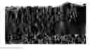
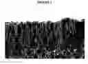
FIG. 1 shows in 20000x a scanning electron microscopy image of a fracture cross section of a cemented carbide insert according to the present invention in which
1. Cemented carbide substrate,
2. Innermost (Ti,A1)N layer and
3. (A1,Cr)2O3 layer.
The coating deposited on a cemented carbide substrate comprises:
a first (innermost) layer of Til-xAlxN with about 0.25 ≦x ≦ about 0.7, preferably x>about 0.4, more preferably x>about 0.6, with columnar grains and a total thickness of about 0.5-5 preferably, about 1-4μm a layer of (Ali -yCry)2O3 with about 0.1 <y <about 0.6, preferably with about 0.3 <y <about 0.55, most preferably y=about 0.5, with a thickness of about 1-5μm, preferably about 1.5-4.5μm, more preferably about 2-4 with columnar grains.
In a further alternative embodiment, there is a thin, less than about 1μm thick, TiN layer on top of the (A1,Cr)2O3 layer.
In a first embodiment, the cemented carbide substrate has a composition of about 9.3-10.9 wt-% Co, preferably about 9.75-10.7 wt-% Co, more preferably about 9.9-10.5 wt-% Co; about 0.5-2.5 wt-%, about preferably 1.0-2.0 wt-%, more preferably about 1.2-1.8 wt-% total amount of the metals Ti, Nb, and Ta; and balance WC. Ti, Ta, and/or Nb may also be partially or totally replaced by other elements from groups IVb, Vb, or VIb of the periodic table. The content of Ti is preferably on a level corresponding to a technical impurity. Preferably, the ratio between the weight concentrations of Ta and Nb is within about 7.0-12.0, preferably about 7.6-11.4, more preferably about 8.2-10.5. The cemented carbide has a coercivity (Hc) of about 10-15, preferably about 11-14, more preferably about 11.5-13.5 kA/m.
In a second embodiment the a cemented carbide substrate has a composition of about 4.7-5.9 wt-% Co, preferably about 4.9-5.6 wt-% Co, more preferably about 5.0-5.5 wt-% Co; about 5.0-10.0 wt-%, preferably about 6.0-9.0 wt-%, more preferably about 7.0-8.0 wt-% total amount of the metals Ti, Nb and Ta; and balance WC. Ti, Ta, and/or Nb may also be partially or totally replaced by other elements from groups IVb, Vb, or VIb of the periodic table. Preferably, the weight ratio between Ta and Nb is about 1.0-5.0, more preferably about 1.5-4.5. The cemented carbide has a coercivity (Hc) of about 11-17, preferably about 12-16, more preferably about 13-15 kA/m.
A cutting insert according to the invention are made by powder metallurgical technique, wet milling of powders forming hard constituents and binder phase, compacting the milled mixture to bodies of desired shape and size and sintering, comprising a cemented carbide substrate, with compositions according to the above, and a coating comprising a layer of (Ti,Al)N and a layer of (AlCr)2O3.
The layer of (Ti,Al)N is arc-deposited using known technique. The (AlCr)2O3 layer is deposited according to Example 1 in US 2007/0000772.
In an alternative embodiment, a thin, less than about 1 TiN top layer is deposited on the (Al,Cr)2O3 layer using known techniques.
In a further preferred embodiment, the cutting tool insert as described above is treated after coating with a wet blasting or brushing operation, such that the surface quality of the coated tool is improved.
The invention also relates to the use of cutting tool inserts according to the above for wet or dry milling of steels and stainless steels at cutting speeds of about 75-600 m/min, preferably about 150-500 m/min, with an average feed, per tooth in the case of milling, of about 0.08-0.5 mm, preferably about 0.1-0.4 mm depending on cutting speed and insert geometry.
Unless defined otherwise, all technical and scientific terms used herein have the same meaning as commonly understood by one of ordinary skill in the art to which this invention belongs. Although any methods and materials similar or equivalent to those described herein can be used in the practice or testing of the present invention, the preferred methods and materials are now described. All publications mentioned hereunder are incorporated herein by reference. Unless mentioned otherwise, the techniques employed or contemplated herein are standard methodologies well known to one of ordinary skill in the art. The materials, methods, and examples are illustrative only and not limiting.
The present invention is further defined in the following Examples, in which all parts and percentages are by weight and degrees are Celsius, unless otherwise stated. It should be understood that these examples, while indicating preferred embodiments of the invention, are given by way of illustration only. From the above discussion and these examples, one skilled in the art can ascertain the essential characteristics of this invention, and without departing from the spirit and scope thereof, can make various changes and modifications of the invention to adapt it to various usages and conditions.
EXAMPLES
Example 1:
Grade A: A cemented carbide substrate with the composition 10.3 wt% Co, 1.35 wt% Ta, 0.15 wt% Nb and balance WC, was produced by conventional milling of the powders, pressing of green compacts and subsequent sintering at 1430° C. The He value of the cemented carbide was 12.5 kA/m, indicating a mean intercept length of about 0.7 μm. The substrate was coated with a 3.0 μm thick layer of (Ti0.5Al0.5)N, according to known arc evaporation technique, columnar grains, a 2.9μm thick layer of columnar (Al0.5Cr0.5)2O3 deposited according to Example 1 in US2007/0000772. FIG. 1 shows in 20000x a scanning electron microscopy image of a fracture cross section of the coated cemented carbide.
Example 2:
Grade B: Example 1 was repeated using a carbide substrate with the composition 5.3 wt% Co, 2.0 wt% Ti, 3.4 wt% Ta, 2.0 wt% Nb, and balance WC. The He value of the cemented carbide was 13.8 kA/m.
Example 3:
Grade C: A layer of 6.0μm Ti0.33Al0.67N was deposited on the substrates according to Examples 1 and 2 using known arc evaporation techniques.
Example 4:
Grades A and C were tested in machining in steel.
| Operation | Face milling |
| Cutter diameter | 125 | mm |
| Material | SS1672 | |
| Insert type | SEEX1204AFTN-M15 |
| Cutting speed | 300 | m/min | |
| Feed | 0.2 | mm/tooth | |
| Depth of cut | 2.5 | mm | |
| Width of cut | 120 | mm | |
| Results | Tool life (min) | |
| Grade A (grade according | 10 | |
| to invention) | ||
| Grade C | 8 | |
The test was stopped at the same maximum flank wear. The wear resistance was much improved with the grade according to the invention.
Example 5:
Grades A and C were tested in machining in stainless steel.
| Operation | Shoulder milling |
| Cutter diameter | 32 | mm |
| Material | SS1672 | |
| Insert type | XOEX120408-M07 |
| Cutting speed | 275 | m/min | |
| Feed | 0.25 | mm/tooth | |
| Dcpth of cut | 3 | mm | |
| Width of cut | 8.8 | mm | |
| Results | Tool life (min) | |
| Grade A (grade according | 8 | |
| to invention) | ||
| Grade C | 5 | |
The test was stopped at the same maximum flank wear. The wear resistance was much improved with the grade according to the invention.
Example 6:
Grades B and C were tested in machining in stainless steel.
| Operation | Interrupted turning | |
| Material | SS2348 | |
| Insert type | CNMG120408-MR3 |
| Cutting speed | 80 | m/min | |
| Feed | 0.3 | mm | |
| Dcpth of cut | 2 | mm | |
| Results | Tool life (cycles) | |
| Grade B (grade according | 5 | |
| to invention) | ||
| Grade C | 3 | |
The test was stopped at the same maximum flank wear. The wear resistance was much improved with the grade according to the invention.
Example 7:
Grades B and C were tested in machining in steel.
| Operation | Interrupted turning | |
| Material | SS1672 | |
| Insert type | CNMG120408-MR3 |
| Cutting speed | 400 | m/min | |
| Feed | 0.3 | mm | |
| Depth of cut | 2 | mm | |
| Results | Tool life (min) | |
| Grade B (grade according | 13 | |
| to invention) | ||
| Grade C | 10 | |
The test was stopped at the same maximum flank wear. The wear resistance was much improved with the grade according to the invention.
When ranges are used herein for physical properties, such as molecular weight, or chemical properties, such as chemical formulae, all combinations and subcombinations of ranges specific embodiments therein are intended to be included.
The disclosures of each patent, patent application, and publication cited or described in this document are hereby incorporated herein by reference, in their entirety.
Those skilled in the art will appreciate that numerous changes and modifications can be made to the preferred embodiments of the invention and that such changes and modifications can be made without departing from the spirit of the invention. It is, therefore, intended that the appended claims cover all such equivalent variations as fall within the true spirit and scope of the invention.
Claims
What is claimed is:1. A method for machining of steel or stainless steel, comprising:
providing a cutting tool insert formed from a cemented carbide substrate and a coating, the coating comprising a first (innermost) layer of Til-xAlxN with about 0.25 ≦x≦ about 0.7 with columnar grains and a total thickness of about 0.5-5μm, and a layer of (All-yCry)2O3 with about 0.1≦y≦about 0.6 with a thickness of about 1-5μm with columnar grains; and
cutting with the cutting tool insert at a cutting speed of about 75-600 m/min with an average feed, per tooth in the case of milling, of about 0.08-0.5 mm.
2. The method according to claim 1, wherein the cutting speed is 150-500 m/min.
3. The method according to claim 1, wherein the average feed is 0.1-0.4 mm.
4. The method according to claim 1, wherein x >about 0.4.
5. The method according to claim 1, wherein x >about 0.6.
6. The method according to claim 1, wherein said first (innermost) layer of Til-xAlxN has a total thickness of about 1-4 μm.
7. The method according to claim 1, wherein about 0.3 <y <about 0.55.
8. The method according to claim 1, wherein y is about 0.5.
9. The method according to claim 1, wherein said layer of (All-yCry)2O3 has a thickness of about 1.5-4.5 μm.
10. The method according to claim 1, wherein said layer of (All-yCry)2O3 has a thickness of about 2-4 μm.
11. The method according to claim 1, wherein said cemented carbide substrate comprises:
about 9.3-10.9 wt% Co;
about 0.5-2.5 wt% total amount of cubic carbides of metals selected from the group consisting of Group IVb metal, Group Vb metal, Group VIb metal, and combinations thereof; and
balance WC,
wherein said cemented carbide substrate has a coercivity of about 10-15 kA/m.
12. The method according to claim 11, wherein said cemented carbide substrate comprises about 9.75-10.7 wt% Co.
13. The method according to claim 11, wherein said cemented carbide substrate comprises about 1.0-2.0 wt% total amount of cubic carbides of the metals of Nb and Ta.
14. The method according to claim 11, wherein said cemented carbide substrate has a coercivity of about 11-14 kA/m.
15. The method according to claim 11, wherein a weight ratio of Ta and Nb is about 7.0-12.0.
16. The method according to claim 11, wherein a weight ratio of Ta and Nb is about 7.6-11.4.
17. The method according to claim 1, wherein said cemented carbide substrate, comprises:
about 4.7-5.9 wt-% Co;
about 5.0-10.0 wt-% total amount of cubic carbides of metals selected from the group consisting of Group IVb metal, Group Vb metal, Group VIb metal, and combinations thereof; and
balance WC;
wherein said cemented carbide substrate has a coercivity of about 11-17 kA/m.
18. The method according to claim 17, wherein said cemented carbide substrate comprises about 4.9-5.6 wt-% Co.
19. The method according to claim 17, wherein said cemented carbide substrate comprises about 5.0-5.5 wt-% Co.
20. The method according to claim 17, wherein said cemented carbide substrate comprises about 6.0-9.0 wt-% total amount of cubic carbides of the metals of Ti, Nb and Ta.
Images & Drawings included:
Sources:
- United States Patent and Trademark Office - verify current appl. status at the USPTO↗
Similar patent applications:
- » 20100255345
Coated PCBN cutting insert, coated PCBN cutting tool using such coated PCBN cutting insert, and method for making the same - » 20080260477
Coated cutting insert and manufacturing method thereof - » 20060147755
Coated cutting insert - » 20070248424
Coated cutting insert and manufacturing method thereof - » 20080242200
Method for manufacturing surface-coated cutting insert - » 20050129987
Coated cutting insert for rough turning - » 20070128469
Surface-coated cutting insert and method for manufacturing the same - » 20060154051
Coated cutting inserts - » 20070128987
Method for manufacturing surface-coated cutting insert - » 20070298230
Coated cutting insert and manufacturing method thereof
Recent applications in this class:
- » 20250230553 2025-07-17
COMPOSITION FOR SURFACE TREATMENT OF MG-CONTAINING GALVANIZED STEEL SHEET AND MG-CONTAINING GALVANIZED STEEL SHEET SURFACE-TREATED USING SAME - » 20230193474 2023-06-22
Al COATING LAYER-EQUIPPED STAINLESS STEEL SHEET - » 20230047998 2023-02-16
Steel component comprising an anti-corrosion layer containing manganese - » 20230012077 2023-01-12
Apparatus, compositions, and methods for stainless-coated steel reinforcement bar - » 20220298646 2022-09-22
Hot stamped steel - » 20220195607 2022-06-23
COATING FILM AND COMPOSITE MATERIAL CONTAINING COATING FILM - » 20210348280 2021-11-11
Composition for surface treatment of Mg-containing galvanized steel sheet and Mg-containing galvanized steel sheet surface-treated using same - » 20210292912 2021-09-23
Solid-Rocket Propellant Coatings - » 20200248317 2020-08-06
Method for Depositing Noble Metal to Carbon Steel Member of Nuclear Power Plant and Method for Suppressing Radionuclide Deposition on Carbon Steel Member of Nuclear Power Plant - » 20200087797 2020-03-19
Modified oxide surface treatment layer for alloys and corresponding methods
Recent applications for this Assignee:
- » 20240173787 2024-05-30
TOOL AND MANUFACTURING METHOD OF IT - » 20240109138 2024-04-04
Cutting insert and milling tool - » 20230205162 2023-06-29
Tool part, system, method, and a computer program for determining a dimension of the tool part - » 20230196043 2023-06-22
Tool part, system, method and computer program product for determining a tool wear - » 20230158577 2023-05-25
Anvil with curved passage for cutting tool - » 20230130145 2023-04-27
Rotary cutting tool with continuous major flutes and discontinuous minor flutes intersecting to form quadrilateral-shaped face portions - » 20230067286 2023-03-02
Cutting insert - » 20220410280 2022-12-29
CUTTING TOOL ASSEMBLY - » 20220212268 2022-07-07
System and method for tracing the use of a cutting edge - » 20220176471 2022-06-09
Cutting tool, a method for manufacturing a cutting tool and a method for machining of a workpiece