Manual spray head
US20110309167A1
2011-12-22
12/818,666
2010-06-18
✅ Patent granted
US 9,243,732 B2
2016-01-26
-
-
Steven J Ganey
Volpe and Koenig, P.C.
2032-11-09
Abstract:
A manual spray head can be connected with a flexible hose line by means of a coupling that has a ball-and-socket joint inserted between the manual spray head and the hose line. This arrangement not only increases the mobility and flexibility between the manual spray head and the flexible hose line, but also permits twisting of the manual spray head relative to the hose line without fear of unscrewing the screw-type connection or similar coupling provided between the manual spray head and the hose line.
Assignee:
- Neoperl GmbH 21 🇩🇪 Muellheim, Germany
Applicant:
Interested in similar patents?
Get notified when new applications in this technology area are published.
Classification:
B05B15/65 » CPC further
Details of spraying plant or spraying apparatus not otherwise provided for; Accessories; Arrangements for mounting, supporting or holding spraying apparatus Mounting arrangements for fluid connection of the spraying apparatus or its outlets to flow conduits
B05B15/652 » CPC further
Details of spraying plant or spraying apparatus not otherwise provided for; Accessories; Arrangements for mounting, supporting or holding spraying apparatus; Mounting arrangements for fluid connection of the spraying apparatus or its outlets to flow conduits whereby the jet can be oriented
B05B15/654 » CPC further
Details of spraying plant or spraying apparatus not otherwise provided for; Accessories; Arrangements for mounting, supporting or holding spraying apparatus; Mounting arrangements for fluid connection of the spraying apparatus or its outlets to flow conduits whereby the jet can be oriented using universal joints
F16L33/00 IPC
Arrangements for connecting hoses to rigid members; Rigid hose connectors, i.e. single members engaging both hoses
E03C1/021 » CPC further
Domestic plumbing installations for fresh water or waste water; Sinks; Plumbing installations for fresh water Devices for positioning or connecting of water supply lines
F16L27/0861 » CPC further
Adjustable joints, Joints allowing movement allowing adjustment or movement only about the axis of one pipe Arrangements of joints with one another and with pipes or hoses
E03C1/08 IPC
Domestic plumbing installations for fresh water or waste water; Sinks; Plumbing installations for fresh water Jet regulators or jet guides , e.g. anti-splash devices
F16L37/088 » CPC further
Couplings of the quick-acting type in which the connection between abutting or axially overlapping ends is maintained by locking members combined with automatic locking by means of a split elastic ring
E03C1/0404 » CPC further
Domestic plumbing installations for fresh water or waste water; Sinks; Plumbing installations for fresh water; Water-basin installations specially adapted to wash-basins or baths Constructional or functional features of the spout
F16L27/08 IPC
Adjustable joints, Joints allowing movement allowing adjustment or movement only about the axis of one pipe
E03C1/02 IPC
Domestic plumbing installations for fresh water or waste water; Sinks Plumbing installations for fresh water
E03C1/04 » CPC further
Domestic plumbing installations for fresh water or waste water; Sinks; Plumbing installations for fresh water Water-basin installations specially adapted to wash-basins or baths
E03C1/0401 » CPC further
Domestic plumbing installations for fresh water or waste water; Sinks; Plumbing installations for fresh water; Water-basin installations specially adapted to wash-basins or baths Fixing a tap to the sanitary appliance or to an associated mounting surface, e.g. a countertop
E03C2001/0415 » CPC further
Domestic plumbing installations for fresh water or waste water; Sinks; Plumbing installations for fresh water; Water-basin installations specially adapted to wash-basins or baths having an extendable water outlet
E03C2001/082 » CPC further
Domestic plumbing installations for fresh water or waste water; Sinks; Plumbing installations for fresh water; Jet regulators or jet guides , e.g. anti-splash devices Outlets connected by an universal joint
F16L33/20 » CPC further
Arrangements for connecting hoses to rigid members; Rigid hose connectors, i.e. single members engaging both hoses Undivided rings, sleeves or like members contracted on the hose or expanded in the hose by means of tools; Arrangements using such members
F16L27/04 » CPC main
Adjustable joints, Joints allowing movement; Universal joints, i.e. with mechanical connection allowing angular movement or adjustment of the axes of the parts in any direction with partly spherical engaging surfaces
B05B1/18 » CPC further
Nozzles, spray heads or other outlets, with or without auxiliary devices such as valves, heating means with multiple outlet openings ; with strainers in or outside the outlet opening Roses; Shower heads
Description
The invention relates to a manual spray head which can be connected with a flexible hose line by means of a coupling.
BACKGROUND OF THE INVENTION
Manual spray heads, which can be used as shower heads or as kitchen spray heads, are known in various constructions. The known manual spray heads are normally connected with a flexible hose line by way of a screw-type coupling, which hose line is, in turn, connected to the water conduit system. The known manual spray heads usually have a spray head grip which carries an external thread on its end region facing away from the spray head. A hose connection is provided on the hose line, which hose connection can be tightly screwed to the external thread of a manual spray head by means of a coupling nut having an internal thread.
However, the screwed connection that is provided in known manual spray heads between the spray head grip and the hose line does not easily allow a rotation of the manual spray head with respect to the longitudinal axis of the hose line, because otherwise the screwed connection between the manual spray head and the hose line may be unintentionally loosened and become loose. The known manual spray heads also normally exhibit wear near the clamping or coupling point to the spray head grip due to overstressing transversely to the longitudinal axis, which is caused by the movement of the manual spray head during its use.
It is therefore an object of the invention to create a manual spray head of the initially mentioned type which is characterized by greater mobility, and especially also by a twisting capability between the manual spray head and the hose line.
SUMMARY OF THE INVENTION
This and other objects and advantages are achieved by the manual spray head according to the invention, in which the coupling provided for using the manual spray head and the hose line has a ball-and-socket joint.
The spray head according to the invention has a coupling which connects the manual spray head with a flexible hose line. This coupling provided for connecting the manual spray head and the hose line has a ball-and-socket joint, inserted between the manual spray head and the hose line. This arrangement not only increases the mobility and flexibility between the manual spray head and the flexible hose line, but also permits twisting of the manual spray head relative to the hose line, without fear of unscrewing the screwed connection or opening-up of a similar coupling provided between the manual spray head and the hose line.
In a structurally simple and preferred embodiment of the invention, the coupling provided for connecting the manual spray head and the hose line is constructed as a screw-type coupling having a spray head connection with an external or internal thread on the manual spray head. The external or internal thread can be connected (preferably detachably) with an internal or external thread on a hose connection of the hose line. When, in this case, a spray head connection with an external thread is provided on the manual spray head and a hose connection with a complementary internal thread is provided on the hose line, commercially available manual spray heads can be mounted on the hose line further developed according to the invention.
The same applies to rotationally rigid plug-type connections or plug-type couplings in this area. The advantages of a better mobility also exist in the case of rotation-free connections or couplings, even if the rotating about the longitudinal axis is carried out at least partly by a non-rotating plug-type connection or plug-type coupling.
Instead, another embodiment according to the invention provides that the coupling provided for the connection of the manual spray head and the hose line is constructed particularly as a rotationally rigid revolving and/or plug-type coupling. Thus, such a revolving and/or plug-type coupling can, for example, also provide a bayonet-type or similar bayonet-lock-type connection between the manual spray head and the hose line.
An exchange of the manual spray head and/or the hose line will be facilitated when the spray head connection and/or the hose connection has a ball-and-socket joint.
In this case, an embodiment is preferred where the hose connection has a ball-and-socket joint which has a first and second joint parts that are connected with one another in a hinged manner and have mutually connected fluid conduits. One joint part carries a hose stem, while the internal or external thread is provided on the other joint part.
In a streamlined embodiment according to the invention that can be produced at low expenditures, the first joint part is held with its universal-ball-joint-shaped or spherical-segment-shaped or similarly spherical front end area of its wall between a form-adapted socket on the second joint part, on the one side, and a joint head on a holding element provided in the inside cavity of the first joint part, on the other side, in a swivelable manner. The holding element penetrates a through-opening of the first joint part by means of a connecting shaft acting upon the second joint part, and mutually connects the fluid conduits of the first joint part as well as the second joint part.
The ball-and-socket joint provided in the coupling further developed according to the invention has two joint parts which are connected with one another in a hinged manner, of which a first joint part has a universal-ball-joint-shaped or spherical-segment-shaped or similarly spherical front end area. In this case, the first joint part is held with its front-side and spherically further developed front-end area between a form-adapted socket on the second joint part, on the one side, and a joint head on a holding element provided in the inside cavity of the first joint part, on the other side, in a swivelable manner. Because the first joint part is therefore securely and firmly held between the second joint part and the holding element, and because the first joint part is secured not only by means of a sealing ring, the ball-and-socket joint has a comparatively high functionality since the holding function and the sealing function are separate from one another and can therefore each be optimized separately. Because the first joint part, which may be arranged on the in-flow or out-flow side of the ball-and-socket joint, is arranged to be swivelable into a socket of the second joint part, the first joint part and the second joint part can be connected with one another without major transitions and particularly without esthetically spoiling variations in diameter. By means of a connecting shaft acting upon the second joint part, the holding element, in this case, penetrates a through-opening of the first joint part, the holding element mutually connecting the fluid conduits of the first joint part as well as of the out-flow part.
In order to integrate the ball-and-socket joint in a manner that is as space-saving as possible in the coupling provided between the manual spray head and the hose line, it is advantageous for one (preferably the first) joint part to have an out-flow side coupling opening with an internal thread, into which internal thread an external thread can be screwed that is provided on the manual spray head.
In this case, a preferred embodiment according to the invention provides that a sleeve-shaped partial area adjoins the spherical front-end area of the first joint part, which partial area carries the internal thread in its sleeve interior that is open on the front side.
It is expedient for the second joint part to carry the hose stem.
To facilitate easy mounting of the component parts of the ball-and-socket joint integrated in the coupling provided between the manual spray head and the hose line, it is expedient for the holding element to be screwable by means of an external thread into an internal thread in the second joint part, and/or for the sleeve interior of the holding element to be further developed as a preferably noncircular tool working surface and particularly as a hexagon socket.
In order to be able to provide a good seal in the area between the joint parts, it is advantageous to provide at least one ring-type seal between the first joint part and the second joint part and/or between the holding element and the first joint part.
It is particularly advantageous to provide at least one ring-type seal and for at least one ring-type seal to be active between the first joint part and the holding element and/or between the first joint part and the second joint part.
It may be expedient for a ring groove for receiving a ring-type seal to be provided at the outer circumference of the holding element, at the inner or outer circumference of the first joint part and/or at the inner circumference of the second joint part in the area of the joint socket.
In a further development of the invention, having its own patentable significance, a spray head fitting having an outlet tube is assigned to the manual spray head. The hose line connected with the manual spray head is guided in the outlet tube, preferably such that it can be pulled out against a restoring force. In this case, it is particularly advantageous for the manual spray head to be held in a readiness position at the outlet tube in such a manner that the coupling between the manual spray head and the hose line is arranged in the tube interior of the outlet tube.
Further developments according to the invention are contained in the description in connection with the drawing and the claims. In the following, the invention will be explained in detail by means of an advantageous embodiment.
BRIEF DESCRIPTION OF THE DRAWINGS
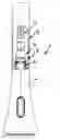
FIG. 1 is a view of a kitchen spray head fitting illustrated in a partially cut fashion, on which a manual spray head is held by means of a pull-down pull-out device, and is connected by way of a flexible hose line to the water conduit network;
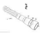
FIG. 2 is a perspective view of the flexible hose line of the kitchen spray head fitting illustrated in FIG. 1 in the area of its hose connection facing the manual spray head;
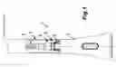
FIG. 3 is a partial longitudinal sectional view of the hose connection of the flexible hose line from FIGS. 1 and 2 having a ball-and-socket joint;
FIG. 4 is a partial longitudinal sectional view of the hose connection from FIGS. 1 to 3 connected with the flexible hose line; and
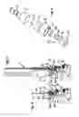
FIG. 5 is an exploded view of the hose connection from FIGS. 3 and 4.
DETAILED DESCRIPTION OF THE INVENTION
FIG. 1 illustrates a kitchen spray head fitting 1 which has an outlet tube 2. In the outlet tube 2, a flexible hose line 3 is guided so that it can be pulled out against a restoring force and is connected with a manual spray head 4 on its out-flow side hose line end. For this purpose, a coupling 5 is provided which connects the manual spray head with the flexible hose line 3.
FIG. 1 indicates that the coupling provided for connecting the manual spray head 4 and the hose line 3 is configured as a screw-type coupling having a spray head connection with an external thread 6 on the manual spray head, which external thread 6 can be connected, preferably detachably, to a hose connection of the hose line 3. In this case, the hose connection illustrated in detail in a partial longitudinal sectional view in FIGS. 3 and 4 has a ball-and-socket joint 7.
The ball-and-socket joint 7 has first and second joint parts 8, 9 (FIG. 2) which are connected with one another in a hinged manner and have mutually connected fluid conduits. While the second joint part 9 carries a hose stem 10 on its front end facing away from the first joint part 8, the first joint part 8 has a sleeve-shaped partial area which carries the internal thread 11 in its sleeve interior open on the front side. The external thread 6 provided on the manual spray head 4 can be releasably screwed into the internal thread 11 of the first joint part. In this case, the front edge of the manual spray head 4 facing the joint part 8 acts upon a sealing ring 24 in the sleeve interior of the joint part 8 in an axially sealing manner.
The end of the hose line 3 facing the coupling 5 is pushed onto the stem 10 (FIG. 3) and is securely and firmly held there by means of a pressing sleeve 25.
FIGS. 1, 3 and 4 illustrate that the first joint part 6 is held with its universal-ball-joint-shaped or spherical-segment-shaped or similarly spherical front end area 12 of its wall between a form-adapted socket 13 on the second joint part 9, on the one side, and a joint head 14 on a holding element 15 provided in the inside cavity of the first joint part 8, on the other side, in a swivelable manner. (See FIGS. 3 and 4.) The holding element 15 penetrates a through-opening 31 of the first joint part 8 by means of a connecting shaft 30 acting upon the second joint part 9 and mutually connects the fluid conduits of the first joint part 8 as well as of the second joint part 9.
The sleeve-shaped partial area adjoins the spherical front-end area 12 of the first joint part 8 on the flow-off side, which sleeve-shaped partial area carries the internal thread 11 in its sleeve interior.
An external thread 17 of the holding element 15 can be screwed into an internal thread in the second joint part 9, the sleeve interior of the holding element 15 being further developed as a preferably noncircular tool working surface and here as a hexagon socket 18. The external thread 17 of the holding element 15 can be releasably screwed into the internal thread in the second joint part 9 and is water-tightly connected therein. At its end area adjoining the external thread 17, the holding element 15 is radially and/or axially sealed off with respect to the joint part 9 by means of the sealing ring 23.
It is easily recognizable in FIGS. 3 and 4 that at least one ring-type seal 20 is provided between the holding element 15 and the first joint part 8. This ring-type seal 20 is active between the first joint part 8 and the holding element 15. For this purpose, a ring groove 21 (FIG. 4) for receiving the ring-type seal 20 is provided at the inner circumference of the first joint part 8.
In FIG. 1, the manual spray head 4 is illustrated in a readiness position, in which the spray head 4 is held at the outlet tube 2 in such a manner that the coupling 5 between the manual spray head 4 and the hose line 3 is arranged completely in the tube interior of the outlet tube 2 in a covered manner. Since the ball-and-socket joint 7 integrated in the coupling 5 ensures not only a swiveling capability but also a twisting capability of the manual spray head 4 relative to the longitudinal axis of the hose line 3, the manual spray head 4 connected with the hose line 3 is distinguished by a high flexibility and twisting capability without fear of an unintentional unintentionally unscrewing the screw-type connection provided between the manual spray head 4 and the hose line 3, and without the occurrence of the usual damage to the hose close to the grip as a result of being overstressed due to movement.
The foregoing disclosure has been set forth merely to illustrate the invention and is not intended to be limiting. Since modifications of the disclosed embodiments incorporating the spirit and substance of the invention may occur to persons skilled in the art, the invention should be construed to include everything within the scope of the appended claims and equivalents thereof.
Claims
1-16. (canceled)
17. A manual spray head having a coupling for connection with a flexible hose line, wherein, the coupling has a ball-and-socket joint.
18. The manual spray head according to claim 17, wherein:
the connection of the manual spray head and the hose line comprises a screw-type coupling; and
an external or internal thread on the manual spray head is detachably connectable with an internal or external thread on a hose connection of the hose line.
19. The manual spray head according to claim 17, wherein the screw-type coupling comprises one of a revolving coupling and a plug-type coupling.
20. The manual spray head according to claim 17, wherein at least one of the spray head connection and the hose connection has a ball-and-socket joint.
21. The manual spray head according to claim 17, wherein:
said ball-and-socket joint includes first and second joint parts, which are connected with one another and have mutually connected fluid conduits; and
one of said joint parts carries a hose stem, with the internal or external thread being provided on the other joint part.
22. The manual spray head according to claim 21, wherein:
the first joint part is swivelably held by a universal-ball-joint shaped or substantially spherical front end area thereof, between a form-adapted socket on the second joint part on one side, and a joint head on a holding element provided in the inside cavity of the first joint part, on the other side;
a connecting shaft of the holding element penetrates a through-opening of the first joint part, and acts upon the second joint part; and
the holding element mutually connects fluid conduits of the first and second joint parts.
23. The manual spray head according to claim 21, wherein one of the first and second joint parts has an out-flow side opening with an internal thread into which an external thread on the manual spray head can be screwed.
24. The manual spray head according to claim 22, wherein:
a sleeve-shaped partial area adjoins the substantially spherical front end area of the first joint part; and
said sleeve-shaped partial area carries the internal thread in its sleeve interior open on the front side.
25. The manual spray head according to claim 21, wherein the second joint part carries the hose stem.
26. The manual spray head according to claim 17, wherein at least one of the following applies:
the holding element is configured such that it is screwable into an internal thread in the second joint part by an external thread; and
the sleeve interior of the holding element comprises a noncircular tool working surface.
27. The manual spray head according to claim 26, wherein the tool working surface comprises a hexagonal socket.
28. The manual spray head according to claim 26, wherein at least one of the following is true:
the external thread of the holding element can be releasably screwed into the internal thread in the second joint part; and
the holding element is connected into the second joint part in a water-tight manner.
29. The manual spray head according to claim 21, wherein at least one ring-type seal is provided between one of i) the first and second joint parts, and ii) the holding element and the first joint part.
30. The manual spray head according to claim 22, wherein:
at least one ring-type seal is provided between one of i) the first joint part and the holding element, and ii) the first joint part and the second joint part.
31. The manual spray head according to claim 22, wherein a ring groove for receiving a ring-type seal is provided at one of i) an outer circumference of the holding element, ii) an inner or outer circumference of the first joint part, and iii) an inner circumference of the second joint part in the area of the joint socket.
32. The manual spray head according to claim 17, wherein:
a spray head fitting having an outlet tube is assigned to the manual spray head; and
the hose line connected with the manual spray head is guided in the outlet tube such that it can be pulled out against a restoring force.
33. The manual spray head according to claim 17, wherein the manual spray head is held in a readiness position at the outlet tube, such that the coupling is arranged between the manual spray head and the hose line in the tube interior of an outlet tube.
34. A spray head coupling comprising:
a first joint part;
a second joint part; and
a holding element; wherein,
one extremity of said first joint part has an external configuration that is at least partially spherical;
said second joint part has a socket which has an interior configuration that conforms to the external configuration of the first joint part;
said extremity of said first joint part is held in said socket of said second joint part by said holding element, a first end of which has a radially extending partially spherical portion that conforms to and bears against an interior surface configuration of said extremity of said first joint part;
a second end of said holding element, opposite said first end, has a connecting shaft that extends through internal openings of said first and second joint parts, and is configured for attachment to a hose end; and
said holding element has an internal conduit that, when connected to a hose end, communicates fluidically with said hose end.
Images & Drawings included:
Sources:
- United States Patent and Trademark Office - verify current appl. status at the USPTO↗
Similar patent applications:
Recent applications in this class:
- » 20250207699 2025-06-26
SCOTCH YOKE GIMBAL JOINT - » 20240125413 2024-04-18
ENHANCED GIMBAL JOINT FOR CONDUITS - » 20240060584 2024-02-22
SURGICAL DEVICE - » 20240011586 2024-01-11
IRRIGATION KINEMATIC JOINT - » 20230143344 2023-05-11
SELF-CENTERING BLIND MATE FLUID COUPLING - » 20230022280 2023-01-26
Tube coupling - » 20220397219 2022-12-15
Enhanced gimbal joint for conduits - » 20200158271 2020-05-21
JOINING PIECE COMPRISING TWO PARTS FITTED ONE INSIDE THE OTHER AND ASSEMBLED TOGETHER, AND ASSOCIATED MANUFACTURING METHOD - » 20170292645 2017-10-12
Anti-binding ball swivel - » 20170097114 2017-04-06
Self-Supported Hose Delivery Assembly
Recent applications for this Assignee:
- » 20240019059 2024-01-18
Water hose connection clip - » 20190170548 2019-06-06
APPARATUS FOR DETECTING STAGNANT WATER - » 20180052021 2018-02-22
Apparatus for detecting stagnant water - » 20170152651 2017-06-01
JET REGULATOR - » 20170052544 2017-02-23
Flow control valve - » 20160202094 2016-07-14
Method and apparatus for detecting stagnant water - » 20130175366 2013-07-11
Sanitary installation element - » 20110309168 2011-12-22
Manual spray head - » 20110139283 2011-06-16
Jet regulator and sanitary water outlet - » 20110036930 2011-02-17
Sanitary functional unit