THERMAL MODULE
US20110315352A1
2011-12-29
12/825,360
2010-06-29
Abstract:
A thermal module includes at least one heat pipe and a heat sink. The heat pipe has a heat absorption end and a heat-spreading end extending in a direction away from the heat absorption end. The heat sink has a heat-spreading face on which multiple radiating fins are disposed and a heat conduction face opposite to the heat-spreading face. The heat conduction face is formed with a reception channel. The heat-spreading end of the heat pipe is press-fitted in the reception channel to integrally connect the heat pipe and the heat sink with each other. The heat-spreading end is flush with the heat conduction face. The heat pipe and the heat sink are connected by means of press fit connection. Therefore, the thermal module can be easily assembled to save working time and lower manufacturing cost. Moreover, the thermal module is able to provide excellent heat dissipation effect.
Assignee:
- ASIA VITAL COMPONENTS CO., LTD. 103 🇹🇼 Sinjhuang City, Taiwan
Interested in similar patents?
Get notified when new applications in this technology area are published.
Classification:
H01L2924/0002 » CPC further
Indexing scheme for arrangements or methods for connecting or disconnecting semiconductor or solid-state bodies as covered by; Technical content checked by a classifier Not covered by any one of groups , and
F28D15/0233 » CPC main
Heat-exchange apparatus with the intermediate heat-transfer medium in closed tubes passing into or through the conduit walls ; Heat-exchange apparatus employing intermediate heat-transfer medium or bodies in which the medium condenses and evaporates, e.g. heat pipes the conduits having a particular shape, e.g. non-circular cross-section, annular
F28D15/0275 » CPC further
Heat-exchange apparatus with the intermediate heat-transfer medium in closed tubes passing into or through the conduit walls ; Heat-exchange apparatus employing intermediate heat-transfer medium or bodies in which the medium condenses and evaporates, e.g. heat pipes Arrangements for coupling heat-pipes together or with other structures, e.g. with base blocks; Heat pipe cores
H01L23/427 » CPC further
Details of semiconductor or other solid state devices; Arrangements for cooling, heating, ventilating or temperature compensation ; Temperature sensing arrangements; Fillings or auxiliary members in containers or encapsulations selected or arranged to facilitate heating or cooling Cooling by change of state, e.g. use of heat pipes
H01L23/467 » CPC further
Details of semiconductor or other solid state devices; Arrangements for cooling, heating, ventilating or temperature compensation ; Temperature sensing arrangements involving the transfer of heat by flowing fluids by flowing gases, e.g. air
H01L2924/00 » CPC further
Indexing scheme for arrangements or methods for connecting or disconnecting semiconductor or solid-state bodies as covered by
F28D15/04 IPC
Heat-exchange apparatus with the intermediate heat-transfer medium in closed tubes passing into or through the conduit walls ; Heat-exchange apparatus employing intermediate heat-transfer medium or bodies in which the medium condenses and evaporates, e.g. heat pipes with tubes having a capillary structure
Description
FIELD OF THE INVENTION
The present invention relates to a thermal module, and more particularly to a thermal module, which can be easily assembled to save working time and facilitate manufacturing process. Therefore, the manufacturing cost of the thermal module is lowered. Moreover, the thermal module is able to provide excellent heat dissipation effect.
BACKGROUND OF THE INVENTION
It is known that when an electronic device (such as a notebook) works, the electronic components of the electronic device, especially the CPU, will generate high heat to cause rise of temperature. The heat generated by the CPU and other heat-generating components must be quickly dissipated. Otherwise, the electronic components will overheat to cause unstable operation or even crash of the entire electronic device. Following the rapid advance of the electronic technologies, the processing speed of various electronic components has been continuously increased. As a result, the electronic components will generate more heat when operating at higher speed. In this case, it is critical to apply a suitable thermal module to the electronic device for efficiently dissipating the heat.
The conventional thermal module is generally assembled by means of press fit or soldering. FIG. 1A shows a conventional thermal module 1 assembled by means of press fit. The thermal module 1 includes a heat pipe 11, a heat sink 10 and a base 13. The heat sink 10 has multiple radiating fins 101, which are piled up to form the heat sink 10. Each of the radiating fins 101 is formed with a perforation 103. A first end of the heat pipe 11 is passed through the perforations 103 and fixed with the radiating fins 101. A second end of the heat pipe 11 is passed through the base 13 and fixed therewith to form the thermal module 1.
When assembled, the first end of the heat pipe 11 must be fitted through the perforations 103 of the radiating fins 101 one by one. Finally, the first end of the heat pipe 11 extends out of the perforation 103 of the last radiating fin 101 and protrudes therefrom. Under such circumstance, the heat pipe 11 is fixed with the heat sink 10.
It can be known from the above that it is troublesome and time-consuming to assemble the radiating fins 101 and the heat pipe 11 by means of press-fit connection. Moreover, the length of the radiating fins 101 is limited by the processing machine so that it is inconvenient to assemble the thermal module.
FIGS. 1B and 1C show a conventional thermal module 1 assembled by means of soldering. The thermal module 1 includes a heat sink 10, a heat pipe 11 and a base 13. The heat sink 10 has multiple radiating fins 101. Each of the radiating fins 101 is formed with a perforation 103. The perforation 103 includes a heat pipe hole 1031 for receiving the heat pipe 11 and a solder hole 1032 for containing therein a solder material 15 such as tin paste. The solder hole 1032 is positioned above the heat pipe hole 1031 in communication therewith. A first end of the heat pipe 11 is fixedly fitted through the heat pipe holes 1031 of the radiating fins 101. A second end of the heat pipe 11 is passed through the base 13 and fixed therewith to form the thermal module 1.
When assembled, the solder material 15 and the heat pipe 11 are previously respectively positioned in the solder holes 1032 and the heat pipe holes 1031 of the radiating fins 101 (as shown in FIG. 1B). Alternatively, the solder material 15 in the form of a paste is filled into the solder holes 1032 and the heat pipe holes 1031 of the radiating fins 101 by means of a tool (not shown) to preliminarily assemble the thermal module 1. Thereafter, the preliminarily assembled thermal module 1 is heated to melt the solder material 15 in the solder holes 1032. The melted solder material 15 will flow from the walls of the solder holes 1032 through the junctions between the solder holes 1032 and the heat pipe holes 1031 into the heat pipe holes 1031. Accordingly, the melted solder material 15 will fill into the gaps between the heat pipe 11 and the radiating fins 101. After cooled and solidified, the heat pipe 11 is fixedly soldered with the radiating fins 101 (as shown in FIGS. 1C and 1D).
According to the aforesaid, after preliminarily assembled, it is necessary to heat and then cool the thermal module 1 to fixedly solder the heat pipe 11 with the radiating fins 101 to form a complete thermal module 1. Such assembling process is complicated and time-consuming so that the manufacturing cost is relatively high.
Moreover, when the melted solder material 15 flows through the junctions between the solder holes 1032 and the heat pipe holes 1031, the solder material 15 is likely to accumulate at the junctions in the form of small tin balls. The tin balls will attach to the radiating fins 101 to cause a poor appearance of the thermal module 1. This will lower the attraction of the product to consumers.
SUMMARY OF THE INVENTION
A primary object of the present invention is to provide a thermal module in which the heat pipe and the heat sink are integrally connected by means of press fit connection. Therefore, the thermal module can be easily assembled to lower manufacturing cost.
A further object of the present invention is to provide the above thermal module, which can be easily assembled to save working time.
A further object of the present invention is to provide the above thermal module, which is able to provide excellent heat dissipation effect.
To achieve the above and other objects, the thermal module of the present invention includes at least one heat pipe and a heat sink. The heat pipe has a heat absorption end and a heat-spreading end extending in a direction away from the heat absorption end. The heat sink has a heat-spreading face on which multiple radiating fins are disposed and a heat conduction face opposite to the heat-spreading face. The heat conduction face is formed with a reception channel. The heat-spreading end of the heat pipe is press-fitted in the reception channel to integrally connect the heat pipe and the heat sink with each other. The heat-spreading end is flush with the heat conduction face. The heat pipe and the heat sink are connected by means of press fit connection. Therefore, the thermal module can be easily assembled to save working time and lower manufacturing cost. Moreover, the thermal module is able to provide excellent heat dissipation effect.
BRIEF DESCRIPTION OF THE DRAWINGS
The structure and the technical means adopted by the present invention to achieve the above and other objects can be best understood by referring to the following detailed description of the preferred embodiments and the accompanying drawings, wherein:
FIG. 1A is a perspective view of a conventional thermal module;
FIG. 1B is a perspective view of another conventional thermal module;
FIG. 1C is a perspective view of the conventional thermal module of FIG. 1B, in which the heat pipe is soldered with the heat sink;
FIG. 1D is a sectional view according to FIG. 1C, showing that the heat pipe is soldered with the heat sink;
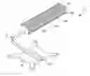
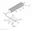
FIG. 2 is a perspective assembled view of a preferred embodiment of the thermal module of the present invention;
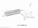
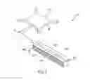
FIG. 3 is a perspective assembled view of the preferred embodiment of the thermal module of the present invention as seen in another direction;
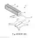
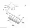
FIG. 4 is a perspective exploded view of the preferred embodiment of the thermal module of the present invention; and
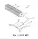
FIG. 5 is a right view of the preferred embodiment of the thermal module of the present invention.
DETAILED DESCRIPTION OF THE PREFERRED EMBODIMENTS
Please refer to FIGS. 2 and 3. According to a preferred embodiment, the thermal module 2 of the present invention includes at least one heat pipe 21 and a heat sink 23. The heat pipe 21 has a heat absorption end 211 and a heat-spreading end 212 extending in a direction away from the heat absorption end 211. The heat absorption end 211 serves to absorb heat, which is quickly transferred to the heat-spreading end 212.
The heat sink 23 has a heat-spreading base 230. The heat-spreading base 230 has a heat-spreading face 231 formed on a first face of the heat-spreading base 230 and a heat conduction face 232 formed on a second face of the heat-spreading base 230 opposite to the heat-spreading face 231. Multiple radiating fins 234 are disposed on the heat-spreading face 231. The heat conduction face 232 is recessed to form a reception channel 235 (as shown in FIG. 4). The heat-spreading end 212 of the heat pipe 21 is press-fitted in the reception channel 235 of the heat sink 23 to integrally connect the heat pipe 21 and the heat sink 23 with each other to form the thermal module 2. The heat-spreading end 212 is flush with the heat conduction face 232.
Referring to FIGS. 4 and 5, the reception channel 235 has a closed side 2351 and an open side 2352 opposite to the closed side 2351. The reception channel 235 is defined between the closed side 2351 and the open side 2352. The heat-spreading end 212 has a plane face 2121 and a non-planar face 2122 axially extending along the plane face 2121. The plane face 2121 is flush with the open side 2352 and the heat conduction face 232. The non-planar face 2122 is tightly and snugly attached to the closed side 2351 of the reception channel 235.
Please refer to FIGS. 3 and 4. The thermal module 2 further includes a heat conduction base 25. The heat conduction base 25 has a groove 251 formed on a third face of the heat conduction base 25. The heat absorption end 211 of the heat pipe 21 is press-fitted in the groove 251 to integrally connect with the heat conduction base 25. A fourth face of the heat conduction base 25 attaches to a heat-generating component (such as a CPU or a south/north bridge chip) to absorb the heat generated by the heat-generating component (not shown). The heat is transferred from the heat conduction base 25 to the heat absorption end 211 of the heat pipe 21 and then to the heat-spreading end 212 thereof. The heat is further transferred from the heat-spreading end 212 to the heat conduction face 232 of the heat sink 23 and then to the radiating fins 234 on the heat-spreading face 231. Through heat exchange process between the radiating fins 234 and the ambient cold air, the heat generated by the heat-generating component can be quickly dissipated.
According to the above arrangement, the heat pipe 21 and the heat sink 23 of the present invention are integrally connected by means of press fit connection. It is unnecessary for the heat pipe 21 to pass through the radiating fins one by one as in the prior art. Therefore, the thermal module can be easily assembled to save working time and facilitate manufacturing process. In this case, the manufacturing cost of the thermal module is lowered. Moreover, the thermal module is able to provide excellent heat dissipation effect. In addition, when recovered for environmental protection purpose, the heat pipe 21 can be easily forcedly separated from the heat sink 23 for classified recovery.
Furthermore, the thermal module 2 of the present invention is assembled without using any solder material. Therefore, the thermal module 2 has a beautiful and tidy appearance to enhance the attraction of the product to consumers.
In comparison with the prior art, the thermal module of the present invention has the following advantages:
1. The thermal module of the present invention is manufactured at lower cost.
2. The thermal module of the present invention can be easily assembled to save working time.
3. The thermal module of the present invention is able to provide excellent heat dissipation effect.
4. The thermal module of the present invention can be easily assembled to facilitate manufacturing process.
The above embodiments are only used to illustrate the present invention, not intended to limit the scope thereof. It is understood that many changes and modifications of the above embodiments can be made without departing from the spirit of the present invention. The scope of the present invention is limited only by the appended claims.
Claims
What is claimed is:1. A thermal module comprising:
at least one heat pipe having a heat absorption end and a heat-spreading end extending in a direction away from the heat absorption end; and
a heat sink having a heat-spreading face and a heat conduction face opposite to the heat-spreading face, multiple radiating fins being disposed on the heat-spreading face, the heat conduction face being recessed to form a reception channel, whereby the heat-spreading end of the heat pipe is press-fitted in the reception channel of the heat sink to integrally connect the heat pipe and the heat sink with each other, the heat-spreading end being flush with the heat conduction face.
2. The thermal module as claimed in claim 1, wherein the heat sink has a heat-spreading base, the heat-spreading face being formed on a first face of the heat-spreading base, the heat conduction face being formed on a second face of the heat-spreading base.
3. The thermal module as claimed in claim 1, further comprising a heat conduction base, the heat conduction base having a groove formed on a third face of the heat conduction base, whereby the heat absorption end of the heat pipe is press-fitted in the groove to integrally connect with the heat conduction base, a fourth face of the heat conduction base attaching to a heat-generating component.
4. The thermal module as claimed in claim 1, wherein the reception channel has a closed side and an open side opposite to the closed side, the closed side and the open side together defining the reception channel.
5. The thermal module as claimed in claim 4, wherein the heat-spreading end has a plane face and a non-planar face axially extending along the plane face, the plane face being flush with the open side and the heat conduction face, the non-planar face being tightly and snugly attached to the closed side of the reception channel.
Images & Drawings included:


Sources:
- United States Patent and Trademark Office - verify current appl. status at the USPTO↗
Similar patent applications:
- » 20230216444
BASE TROUGH FOR A THERMAL MODULE, THERMAL MODULE COMPRISING SUCH BASE TROUGH, A SYSTEM FOR EXTRACTING THERMAL ENERGY AND THE USE OF SUCH BASE TROUGH FOR EXTRACTING THERMAL ENERGY FROM SUNLIGHT - » 20160165750
THERMAL MODULE AND ELECTRONIC DEVICE HAVING THE THERMAL MODULE - » 20240389269
THERMAL MODULE AND JOINING METHOD FOR HERMETICALLY SEALED ENCLOSURE OF A THERMAL MODULE USING A CAPILLARY JOINT - » 20230045376
REFRIGERANT THERMAL MANAGEMENT MODULE, THERMAL MANAGEMENT SYSTEM, AND VEHICLE - » 20200191042
Liquid driven thermal module and thermal management system - » 20220414888
Thermal image processing device, thermal image processing module, thermal image processing method, and recording medium - » 20240208119
MANUFACTURING PROCESS OF NOVEL LIGHT-WEIGHT VACUUM THERMAL INSULATION MODULE, AND VACUUM THERMAL INSULATION MODULE - » 20130055726
MAGNETIC THERMAL MODULE AND MAGNETIC THERMAL DEVICE - » 20090034327
Thermal-emitting memory module, thermal-emitting module socket, and computer system - » 20250058601
THERMAL MANAGEMENT INTEGRATED MODULE, THERMAL MANAGEMENT SYSTEM, AND VEHICLE
Recent applications in this class:
- » 20250067519 2025-02-27
THREE-DIMENSIONAL HEAT TRANSFER DEVICE - » 20250052511 2025-02-13
VAPOR CHAMBER HEATSINK ASSEMBLY - » 20250012514 2025-01-09
HEATPIPE WITH GRADUATED CONDENSER PORTION AND CONSTANT RATIO BETWEEN WICK THICKNESS AND CROSS-SECTION AREA - » 20240426558 2024-12-26
DYNAMICALLY ENHANCING HEAT TRANSFER THROUGH HEAT PIPES - » 20240410656 2024-12-12
COMPOSITE HEAT EXCHANGE APPARATUS FOR A TURBINE ENGINE - » 20240361082 2024-10-31
VAPOR CHAMBER - » 20240344773 2024-10-17
VAPOR CHAMBER DEVICE - » 20240247877 2024-07-25
EMBEDDED-LATTICE-JIG, ISOTHERMAL, TRUSS-PLATE APPARATUS AND METHOD - » 20240175638 2024-05-30
3D VAPOR CHAMBER - » 20240125559 2024-04-18
BODY SHEET FOR VAPOR CHAMBER, VAPOR CHAMBER, AND ELECTRONIC APPARATUS
Recent applications for this Assignee:
- » 20130337169 2013-12-19
Heat-dissipation unit coated with oxidation-resistant nano thin film and method of depositing the oxidation-resistant nano thin film thereof - » 20130333864 2013-12-19
Heat-Dissipation Unit Coated with Oxidation-Resistant Nano Thin Film and Method of Depositing the Oxidation-Resistant Nano Thin Film Thereof - » 20130118012 2013-05-16
Flat plate heat pipe and method for manufacturing the same - » 20130118011 2013-05-16
Plate-type heat pipe sealing structure and manufacturing method thereof - » 20120267083 2012-10-25
INCLINED WAVED BOARD AND HEAT EXCHANGER THEREOF - » 20120213578 2012-08-23
Mounting rack structure and mounting hole adapter thereof - » 20120171024 2012-07-05
BEARING HOLDING STRUCTURE AND FAN MODULE USING SAME - » 20120170882 2012-07-05
FAN BEARING RETAINING STRUCTURE - » 20120161553 2012-06-28
Water-cooling structure for electric motor - » 20120160454 2012-06-28
HEAT EXCHANGER