Oil pumping unit
US20110318199A1
2011-12-29
13/171,495
2011-06-29
✅ Patent granted
US 8,746,093 B2
2014-06-10
-
-
Charles Freay | Alexander Comley
Matthias Scholl P.C. | Matthias Scholl
2032-09-11
Abstract:
A crank-type non-beam pumping unit, including a belt, a foundation, a crown sheave, a frame, a support rod, a belt pulley, a pin shaft, a crank, a transmission shaft, and a bracket. The bottom of the frame is disposed on the foundation, and the top of the frame is supported by the support rod. The top of the support rod is hinge connected to the frame, and the bottom of the support rod is hinge connected to the foundation. The bracket is disposed on the foundation, the transmission shaft is disposed on the bracket, and the crank is disposed on the transmission shaft. The crank rotates synchronously with the transmission shaft, and the belt pulley is disposed on one end of the crank via the pin shaft. One end of the belt bypasses the crown sheave, and is connected to a smooth sucker rod.
Inventors:
- Minxuan WANG 2 🇨🇳 Dongying, China
- Guangqi GAO 3 🇨🇳 Dongying, China
- Zhengquan CHENG 2 🇨🇳 Dongying, China
- Bin WEI 3 🇨🇳 Dongying, China
- Jianli XU 1 🇨🇳 Dongying, China
- Zhonghui ZHANG 1 🇨🇳 Dongying, China
- Bingsheng LIU 1 🇨🇳 Dongying, China
- Yan LUO 1 🇨🇳 Dongying, China
- Zejun ZHU 1 🇨🇳 Dongying, China
Assignee:
- CHINA PETROLEUM CHEMICAL CORPORATION 659 🇨🇳 BEIJING, China
- Oil Production Technology Research Institute of Shengli Oilfield Branch of China Petroleum Chemical Corporation 1 🇨🇳 Dongying, China
Applicant:
Interested in similar patents?
Get notified when new applications in this technology area are published.
Classification:
E21B43/126 » CPC main
Methods or apparatus for obtaining oil, gas, water, soluble or meltable materials or a slurry of minerals from wells; Methods or apparatus for controlling the flow of the obtained fluid to or in wells; Lifting well fluids Adaptations of down-hole pump systems powered by drives outside the borehole, e.g. by a rotary or oscillating drive
Y10T74/18176 » CPC further
Machine element or mechanism; Mechanical movements; Rotary to or from reciprocating or oscillating Crank, pitman, lever, and slide
Y10T74/18182 » CPC further
Machine element or mechanism; Mechanical movements; Rotary to or from reciprocating or oscillating; Crank, pitman, lever, and slide Pump jack type
Y10T74/18968 » CPC further
Machine element or mechanism; Mechanical movements; Reciprocating to or from oscillating; Lever and slide Flexible connections
F04B53/00 IPC
Component parts, details or accessories not provided for in, or of interest apart from, groups - or -
F16H21/32 IPC
Gearings comprising primarily only links or levers, with or without slides all movement being in, or parallel to, a single plane for interconverting rotary motion and reciprocating motion; Crank gearings; Eccentric gearings with one connecting-rod and one guided slide to each crank or eccentric with additional members comprising only pivoted links or arms
F16H21/44 IPC
Gearings comprising primarily only links or levers, with or without slides all movement being in, or parallel to, a single plane for conveying or interconverting oscillating or reciprocating motions
F04B17/00 IPC
Pumps characterised by combination with, or adaptation to, specific driving engines or motors
Description
CROSS-REFERENCE TO RELATED APPLICATIONS
Pursuant to 35 U.S.C. § 119 and the Paris Convention Treaty, this application claims the benefit of Chinese Patent Application No. 201010226167.1 filed on Jun. 29, 2010, the contents of which are incorporated herein by reference.
BACKGROUND OF THE INVENTION
1. Field of the Invention
The invention relates to a pumping unit, and more particularly to a crank-type non-beam pumping unit.
2. Description of the Related Art
Nowadays pumping units are widely used, and are divided into two types: a beam pumping unit, and a vertical pumping unit. The beam pumping unit features large number of components, complex structure, high production cost, low mechanical efficiency, and poor economy. As for the vertical pumping unit, there are several problems therewith: transportation thereof is inconvenient, and special equipments must be used to move it during workover operation; moreover, this type of pumping unit cannot meet requirement for coordinate installation of multiple pumping units among multiple oil wells.
SUMMARY OF THE INVENTION
In view of the above-described problem, it is an objective of the invention to provide a crank non-beam pumping unit that is capable of addressing the above-mentioned problems.
To achieve the above objectives, in accordance with one embodiment of the invention, provided is a crank non-beam pumping unit, comprising a belt, a foundation, a crown sheave, a frame, a support rod, a belt pulley, a pin shaft, a crank, a transmission shaft, and a bracket, the bottom of the frame is disposed on the foundation, the top of the frame is supported by the support rod, the top of the support rod is hinge connected to the frame, the bottom of the support rod is hinge connected to the foundation, the bracket is disposed on the foundation, the transmission shaft is disposed on the bracket, the crank is disposed on the transmission shaft, the bracket and the crank are symmetric, the crank rotates synchronously with the transmission shaft, the belt pulley is disposed on one end of the crank via the pin shaft, one end of the belt bypasses the crown sheave, and is connected to a smooth sucker rod, and the other end of the belt is wrapped on the belt pulley.
In a class of this embodiment, two or more of the pumping units are serially connected, the crown sheave, the frame, the support rod, the belt, the belt pulley, the pin shaft, the crank, the transmission shaft, the bracket, and the foundation of each of the pumping units is the same, one end of the transmission shaft is connected to a power supply, the other end of the transmission shaft is connected to a crank of a first pumping unit, the other crank of the first pumping unit is connected to an end of a second transmission shaft, the other end of the second transmission shaft is connected to a crank of a second pumping unit, an end of a third transmission shaft is connected to the other crank of the second pumping unit, cranks of the pumping units are staggered mounted, and stagger angles between cranks of each of the pumping unit are the same.
In a class of this embodiment, the other end of the belt bypasses the belt pulley, and is fixed on the foundation.
In a class of this embodiment, a length regulator is disposed on the support rod.
In a class of this embodiment, the bottom of the frame is hinge connected to the foundation.
Advantages of the invention comprise: as a power supply drives the transmission shaft to rotate, the crank synchronously rotates therewith, the belt pulley rotates with respect to the transmission shaft, and a connection terminal between the belt and the smooth sucker rod reciprocally moves up and down, and drives the smooth sucker rod to pump oil; the invention has no beam, and thus structure thereof is simple; multiple pumping units can be connected to the transmission shaft, which makes the invention meet requirement for coordinate installation of multiple pumping units among multiple oil wells, and thus improving mechanical efficiency, and reducing power consumption, and therefore, the invention has significant economic benefit.
BRIEF DESCRIPTION OF THE DRAWINGS
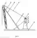
FIG. 1 is a schematic view of a crank non-beam pumping unit of an exemplary embodiment of the invention; and
FIG. 2 illustrates installation of a belt pulley, a pin shaft, a crank, a transmission shaft, and a bracket of the invention.
DETAILED DESCRIPTION OF THE EMBODIMENTS
Further description of the invention will be given below in conjunction with accompanying drawings.
As shown in FIG. 1, a crank non-beam pumping unit of the invention comprises a belt 4, a foundation 11, a crown sheave 1, a frame 2, a support rod 3, a belt pulley 6, a pin shaft 7, a crank 8, a transmission shaft 9, and a bracket 10.
The bottom of the frame 2 is disposed on the foundation 11, and the top of the frame 2 is supported by the support rod 3.
The top of the support rod 3 is hinge connected to the frame 2, and the bottom of the support rod 3 is hinge connected to the foundation 11.
The bracket 10 is disposed on the foundation 11.
The transmission shaft 9 is disposed on the bracket 10, the crank 8 is disposed on the transmission shaft 9, and the bracket 10 and the crank 8 are symmetric.
The crank 8 rotates synchronously with the transmission shaft 9.
The belt pulley 6 is disposed on one end of the crank 8 via the pin shaft 7.
One end of the belt 4 bypasses the crown sheave 1, and is connected to a smooth sucker rod, and the other end of the belt 4 is wrapped on the belt pulley 6.
The other end of the belt 4 bypasses the belt pulley 6, and is fixed on the foundation 11.
A length regulator 5 is disposed on the support rod 3. By adjusting the length regulator 5, the frame 2 leans back and is beyond movement range of a travelling block of a production rig. At this time, workover operation can be done, and no extra equipment is required to move it, and the workover operation is very convenient.
The bottom of the frame 2 is hinge connected to the foundation 11. As the frame 2 leans back by adjustment of the length regulator 5, the frame 2 rotates with respect to a hinge connection point between the bottom thereof and the foundation 11.
The crank non-beam pumping unit of the invention can be used independently, or multiple crank non-beam pumping units can be coordinately used among multiple oil wells, which make the invention especially suitable for cluster wells production.
As shown in FIG. 2, if multiple crank non-beam pumping units are coordinately used among multiple oil wells, multiple transmission shafts 9 are used. One transmission shaft 9 is connected to a crank 8, another transmission shaft 9 is connected to the other crank 8, a further transmission shaft 9 is connected to a power supply, and operates as a driving shaft, a still further transmission shaft 9 is connected to a crank of another pumping unit, and operates as a driven shaft. Thus, multiple crank non-beam pumping units can be coordinately used among multiple oil wells. Two or more of the pumping units are serially connected, the crown sheave 1, the frame 2, the support rod 3, the belt 4, the belt pulley 6, the pin shaft 7, the crank 8, the transmission shaft 9, the bracket 10, and the foundation 11 of each of the pumping units is the same, one end of the transmission shaft 9 is connected to a power supply, the other end of the transmission shaft 9 is connected to a crank 8 of a first pumping unit, the other crank 8 of the first pumping unit is connected to an end of a second transmission shaft 9A, the other end of the second transmission shaft 9A is connected to a crank 8 of a second pumping unit, an end of a third transmission shaft 9B is connected to the other crank 8 of the second pumping unit, and cranks 8 of the pumping units are staggered mounted. As shown in FIG. 2, a stagger angle between cranks 8 of the pumping units is 180°, and thus alternating loads on uplinks and downlinks are balanced, which improves mechanical efficiency of the oil wells. If three pumping units are connected, the stagger angle is 120°.
An output shaft on a reduction box of the power supply is integrated with the transmission shaft 9.
As the crank non-beam pumping unit of the invention is used independently, and alternating loads are comparatively large, a counterweight can be added on the other end of the crank 8 whereby facilitating balance.
As the crank non-beam pumping unit of the invention is used independently, and alternating loads are comparatively large, a counterweight can be added on the other end of the crank 8 whereby facilitating balance.
While particular embodiments of the invention have been shown and described, it will be obvious to those skilled in the art that changes and modifications may be made without departing from the invention in its broader aspects, and therefore, the aim in the appended claims is to cover all such changes and modifications as fall within the true spirit and scope of the invention.
Claims
The invention claimed is:1. An oil pumping unit, comprising:
a belt (4);
a foundation (11);
a crown sheave (1);
a frame (2);
a support rod (3);
a belt pulley (6);
a pin shaft (7);
a crank (8);
a transmission shaft (9); and
a bracket (10);
wherein
the bottom of said frame (2) is disposed on said foundation (11);
the top of said frame (2) is supported by said support rod (3);
the top of said support rod (3) is hinge connected to said frame (2);
the bottom of said support rod (3) is hinge connected to said foundation (11);
said bracket (10) is disposed on said foundation (11);
said transmission shaft (9) is disposed on said bracket (10);
said crank (8) is disposed on said transmission shaft (9);
said bracket (10) and said crank (8) are symmetric;
said crank (8) rotates synchronously with said transmission shaft (9);
said belt pulley (6) is disposed on one end of said crank (8) via said pin shaft (7);
one end of said belt (4) bypasses said crown sheave (1), and is connected to a smooth sucker rod; and
the other end of said belt (4) is wrapped on said belt pulley (6).
2. The unit of claim 1, wherein
two or more of said pumping units are serially connected;
said crown sheave (1), said frame (2), said support rod (3), said belt (4), said belt pulley (6), said pin shaft (7), said crank (8), said transmission shaft (9), said bracket (10), and said foundation (11) of each of said pumping units is the same;
one end of said transmission shaft (9) is connected to a power supply;
the other end of said transmission shaft (9) is connected to a crank (8) of a first pumping unit;
the other crank (8) of said first pumping unit is connected to an end of a second transmission shaft (9A);
the other end of said second transmission shaft (9A) is connected to a crank (8) of a second pumping unit;
an end of a third transmission shaft (9B) is connected to the other crank (8) of said second pumping unit; and
cranks (8) of said pumping units are staggered mounted.
3. The unit of claim 1, wherein the other end of said belt (4) bypasses said belt pulley (6), and is fixed on said foundation (11).
4. The unit of claim 1, wherein a length regulator (5) is disposed on said support rod (3).
5. The unit of claim 1, wherein the bottom of said frame (2) is hinge connected to said foundation (11).
Images & Drawings included:


Sources:
- United States Patent and Trademark Office - verify current appl. status at the USPTO↗
Similar patent applications:
- » 20190345852
Oil pump and balancer unit of oil pump integrated type - » 20120070318
Oil pump unit with variable flow rate - » 20190145228
Electric machine driving method and system under non-conventional work mode of oil pumping unit - » 20140238160
Oil pumping unit with pinion reciprocating on rack - » 20080073153
Oil pump unit for internal combustion engine - » 20070114015
Oil pumping unit using an electrical submersible pump driven by a circular linear synchronous three-phase motor with rare earth permanent magnet - » 20120070317
Oil pump unit with variable flow rate - » 20080206078
Electric pump unit and electric oil pump apparatus - » 20100008797
Electric pump unit and electric oil pump - » 20050196286
Oil well pumping unit and method therefor
Recent applications in this class:
- » 20250223892 2025-07-10
A PUMPING UNIT USING A CONCENTRIC DUAL-AXIS DRIVE CONTROL DEVICE - » 20250027394 2025-01-23
Fluid lift system - » 20240263548 2024-08-08
Methods and systems to control flow and heat transfer between subsurface wellbores connected hydraulically by fractures - » 20240218766 2024-07-04
CRUDE OIL HYDRAULIC LIFT - » 20240052733 2024-02-15
PRODUCTION INLET ASSEMBLIES FOR A SUBTERRANEAN WELLBORE - » 20240044231 2024-02-08
Multi-phase controlled multi-well pumping unit - » 20230193729 2023-06-22
Method for remotely shutting down downhole unit of rotary steering system from ground - » 20230039266 2023-02-09
METHODS AND APPARATUS FOR CREATING AND USING A MULTI-DIMENSIONAL DATA MATRIX TO IDENTIFY AN OPTIMUM ROTARY STEERABLE SYSTEM SETTING - » 20220220835 2022-07-14
Subsea variable speed drive apparatus - » 20220195851 2022-06-23
Method of lifting fluids from a producing formation to a surface location
Recent applications for this Assignee:
- » 20250180775 2025-06-05
METHOD FOR CALIBRATING PRESTACK SEISMIC INVERSION USING FULLY CONNECTED NEURAL NETWORKS - » 20250129703 2025-04-24
MUD PULSE GENERATION SYSTEM BASED ON TWO-WAY COMMUNICATION - » 20240417508 2024-12-19
HALOGENATED POLYPHOSPHATE POLYOL AND PREPOLYMER AND PREPARATION METHOD THEREFOR, AS WELL AS POLYUREA ELASTOMER COMPOSITION AND POLYUREA ELASTOMER AND APPLICATION - » 20240390714 2024-11-28
Flame Arrester Capable of Automatically Eliminating Defects of Fire Arresting Portion - » 20240384186 2024-11-21
Hydrocracking Process and System - » 20240376369 2024-11-14
Application of naphthenic imidazoline in inhibiting formation of natural gas hydrates and composition containing same - » 20240376242 2024-11-14
POLYMER, THICKENING AGENT, AND PREPARATION METHOD THEREFOR - » 20240368490 2024-11-07
LUBRICITY IMPROVER COMPOSITION FOR FUEL OIL AND USE THEREOF - » 20240288414 2024-08-29
WATER QUALITY TESTING METHOD AND WATER QUALITY TESTING APPARATUS - » 20240270958 2024-08-15
Microspheric ionomer having cross-linked structure, preparation method therefor, applications thereof, and preparation system thereof