Locking screw
US20120009042A1
2012-01-12
12/916,589
2010-10-31
✅ Patent granted
US 8,475,101 B2
2013-07-02
-
-
Victor Batson | Tyler Johnson
Altis Law Group, Inc.
2031-07-31
Abstract:
A locking screw for connecting two or more articles together is provided. The screw includes an externally threaded shaft, a head, and an elastic member. The head defines a chamber in which a spiral groove is defined. The shaft extends from the bottom of the chamber; and the elastic member is arranged around the shaft and one end of the elastic member is received in the spiral groove of the chamber and another end abuts against an article. The elastic member can be rotated around the longitudinal axis of the shaft, to change the length of the elastic member, so that enough tension is created to ensure locking the screw in place and prevent any rotation, thus maintain a tight engagement among the articles.
Inventors:
- PENG-YU CHEN 2 🇨🇳 Shenzhen City, China
- HUNG-TI SU 4 🇹🇼 Tu-Cheng, Taiwan
- Peng-Yu Chen 2 🇨🇳 Shenzhen, China
- Hung-Ti Su 4 🇹🇼 Taipei Hsien, Taiwan
Assignee:
- HON HAI PRECISION INDUSTRY CO., LTD. 12,833 🇹🇼 Tu-Cheng, Taiwan
- FU TAI HUA INDUSTRY (SHENZHEN) CO., LTD. 489 🇨🇳 ShenZhen City, China
- HON HAI PRECISION INDUSTRY CO., LTD. 10,014 🇹🇼 New Taipei, Taiwan
- FU TAI HUA INDUSTRY (SHENZHEN) CO., LTD. 815 🇨🇳 Shenzhen, China
Applicant:
Interested in similar patents?
Get notified when new applications in this technology area are published.
Classification:
F16F1/12 IPC
Springs made of steel or other material having low internal friction ; Wound, torsion, leaf, cup, ring or the like springs, the material of the spring not being relevant; Wound springs Attachments or mountings
F16B5/0266 » CPC main
Joining sheets or plates, e.g. panels, to one another or to strips or bars parallel to them by means of fastening members using screw-thread using springs
F16B31/04 » CPC further
Screwed connections specially modified in view of tensile load; Break-bolts for maintaining a tensile load
F16B35/06 » CPC further
Screw-bolts; Stay-bolts; Screw-threaded studs; Screws; Set screws with specially-shaped head or shaft in order to fix the bolt on or in an object Specially-shaped heads
F16B39/24 IPC
Locking of screws, bolts or nuts in which the locking takes place during screwing down or tightening by means of washers, spring washers, or resilient plates that lock against the object
F16B39/26 IPC
Locking of screws, bolts or nuts in which the locking takes place during screwing down or tightening by means of washers, spring washers, or resilient plates that lock against the object with spring washers fastened to the nut or bolt-head
F16F1/06 IPC
Springs made of steel or other material having low internal friction ; Wound, torsion, leaf, cup, ring or the like springs, the material of the spring not being relevant; Wound springs with turns lying in cylindrical surfaces
Description
BACKGROUND
1. Technical Field
The present disclosure relates to screws and, more particularly, to a screw having an elastic member to prevent the screw from loosening.
2. Description of Related Art
Screws are used to connect various articles together. Special nuts and lock washers are often used to prevent a screw from loosening. The need for additional elements to prevent loosening adds to the expense and complication of attaching articles together.
BRIEF DESCRIPTION OF THE DRAWINGS
The components in the drawing are not necessarily drawn to scale, the emphasis instead being placed upon clearly illustrating the principles of the loosening proof screw.
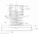
The drawing is a schematic view of a locking screw in accordance with an exemplary embodiment with a head of the screw cut-away to exposed internal details.
DETAILED DESCRIPTION
Referring to the drawing, a locking screw 1 can be used to connect two or more articles together. In the embodiment, a first article 40 and a second article 50 are illustrated as an example. The locking screw 1 includes an externally threaded shaft 10, a head 20, and an elastic member 30. The articles 40 and 50 can be connected together by the engagement of the screw 1 with internally threaded holes of the articles 40 and 50.
The head 20 defines a chamber 201 in which a spiral groove 2011 is defined. The spiral groove 2011 is configured to receive one end of the elastic member 30. The shaft 10 extends from the bottom of the chamber 201.
In use, the elastic member 30 is arranged around the shaft 10. One end of the elastic member 30 is received in the spiral groove 2011 of the chamber 201, and the other opposite end of the elastic member 30 abuts against the top surface 401 of the first article 40 when the shaft 10 is screwed into the threaded holes of the first article 40 and the second article 50. Tension produced between the elastic member 30, the head 20, the first articles 40 and the second article 50 can be adjusted by rotating the elastic member 30 around the longitudinal axis of the shaft 10 to change the length of the elastic member 30. In the embodiment, the elastic member 30 is a coil spring.
Once the screw 1 is installed, tension created by compression of the elastic member 30 ensures threads of the shaft 10 steadily resist against the internal threads of the first and second articles 40,50 so that the screw 1 cannot back out of the through holes of the articles 40, 50, such as from vibration. The elastic member 30 can be rotated around the longitudinal axis of the shaft 10, to change the length of the elastic member 30, so that enough tension is created to ensure locking the screw 1 in place and prevent any rotation, thus maintain a tight engagement between the first article 40 and the second article 50.
In the embodiment, a graduation line 60 can be set on the lateral surface of the shaft 10 so that, for example, when many screws 1 are employed they can all be adjusted to the same degree of tension, and is configured to indicate the distance D from the end 202 of the head 20 to the top surface 401 of the first article 40. For example, it means that the distance D is a standard distance when the graduation line 60 is flush with the top surface 401. The distance D can be changed by rotating the elastic member 30 around the longitudinal axis of the shaft 10 through auxiliary tools, so that the length of the elastic member 30 from the end 202 to the top surface 401 can be changed, and the tension given by the elastic member 30 can be changed accordingly.
In the embodiment, the locking screw 1 also includes flattened portion 70 on lateral sides of the elastic member 30 to provide gripping surfaces for tools used to adjust the elastic member 30.
Although the current disclosure has been specifically described on the basis of the exemplary embodiment thereof, the disclosure is not to be construed as being limited thereto. Various changes or modifications may be made to the embodiment without departing from the scope and spirit of the disclosure.
Claims
What is claimed is:1. A locking screw, comprising:
a head defining a chamber in which a spiral groove is defined;
an externally threaded shaft extending from a bottom of the chamber; and
an elastic member arranged around the shaft and one end of the elastic member received in the spiral groove of the chamber, and another end of the elastic member to abut against an article when the shaft is screwed into the article.
2. The locking screw according to claim 1, wherein the elastic member is a coil spring.
3. The locking screw according to claim 1, wherein a graduation line is set on the lateral surface of the externally threaded shaft.
4. The locking screw according to claim 1, further comprising flattened portion on lateral sides of the elastic member to provide gripping surfaces for tools used to adjust the elastic member.
Images & Drawings included:
Sources:
- United States Patent and Trademark Office - verify current appl. status at the USPTO↗
Similar patent applications:
- » 20060009771
Bone stabilization system including plate having fixed-angle holes together with unidirectional locking screws and surgeon-directed locking screws - » 20170319248
VARIABLE-ANGLE LOCKING SCREWS, AND BONE PLATE SYSTEMS THAT INCLUDE VARIABLE-ANGLE LOCKING SCREWS - » 20170105774
Orthopedic locking screw for an orthopedic fastening system and method of securing an orthopedic locking screw - » 20110238123
Implant plate screw locking system and screw having a locking member - » 20090024170
Implant plate screw locking system and screw having a locking member - » 20100114108
Multiplanar taper lock screw and lock indicator gauge - » 20150094774
BONE FIXATION ASSEMBLY, INCLUDING S-SHAPED RESILIENT LOCK FOR SCREW LOCKING CLIPS - » 20100114180
Multi-planar, taper lock screw with additional lock - » 20090253294
Terminal lock device for screw lock terminal - » 20100100136
Poly-axial pedicle screw implements and lock screw therefor
Recent applications in this class:
- » 20250290531 2025-09-18
Hybrid Compensation Nut - » 20250067292 2025-02-27
CONNECTOR FOR FIXING LAMINATE BETWEEN TWO VERTICAL PLATES - » 20240376917 2024-11-14
COMPACT SCREW-LATCHING ASSEMBLY WITH OVERDRIVE PROTECTION - » 20240376916 2024-11-14
Removable shoulder screw - » 20240328445 2024-10-03
ANTI-WEAR SCREW - » 20240093707 2024-03-21
FASTENING BODY - » 20230340978 2023-10-26
Floating fastener with shock-absorbing structure - » 20230213049 2023-07-06
BOLTING DEVICE - » 20230193935 2023-06-22
Fastener structure - » 20230138233 2023-05-04
Fastener Assembly and Method of Use
Recent applications for this Assignee:
- » 20250218287 2025-07-03
METHOD OF GENERATING AND PROMPTING TRAFFIC INFORMATION, AND ROADSIDE DEVICE THEREOF - » 20250178535 2025-06-05
METHOD FOR CONSTRUCTING 3D PANORAMIC VIEW MODEL, VEHICLE-MOUNTED DEVICE, AND STORAGE MEDIUM - » 20250074444 2025-03-06
METHOD FOR EARLY WARNING A BLIND AREA, ELECTRONIC DEVICE AND STORAGE MEDIUM - » 20240416754 2024-12-19
DISPLAY CONTROL DEVICE, DISPLAY EQUIPMENT, AND VEHICLE EMPLOYING DEVICE - » 20240411051 2024-12-12
Light-emitting device array and optical transceiver system having the same - » 20240324114 2024-09-26
DISPLAY CONTROL DEVICE AND VEHICLE EMPLOYING DEVICE - » 20240295957 2024-09-05
METHOD FOR CONTROLLING ELECTRONIC DEVICE, ELECTRONIC DEVICE AND COMPUTER STROAGE MEDIUM EMPLOYING METHOD - » 20240257357 2024-08-01
METHOD FOR DETECTING OBSTACLES, ELECTRONIC DEVICE, AND STORAGE MEDIUM - » 20240203133 2024-06-20
LANE LINE RECOGNITION METHOD, ELECTRONIC DEVICE AND STORAGE MEDIUM - » 20240194999 2024-06-13
Robot using limiting device for locking battery