Method for detecting the clutch condition
US20120041657A1
2012-02-16
13/197,120
2011-08-03
✅ Patent granted
US 8,972,133 B2
2015-03-03
-
-
Jerrah Edwards
Kenyon & Kenyon LLP
2033-03-07
Abstract:
A method for detecting the clutch condition in engine-powered vehicles. To ensure a reliable detection of the clutch condition even in extreme driving situations, the engine torque of at least one vehicle engine is increased or reduced automatically by pulses and the response of the engine to the torque pulse is evaluated.
Inventors:
- Ulrich Goennenwein 1 🇩🇪 Untergruppenbach, Germany
- Muhammad Rauf Hameed 1 🇩🇪 Heilbronn, Germany
- Ruediger Poggenburg 2 🇩🇪 Vaihingen/Enz, Germany
Assignee:
- Robert Bosch GMBH 19,123 🇩🇪 Stuttgart, Germany
Applicant:
Interested in similar patents?
Get notified when new applications in this technology area are published.
Classification:
B60W2510/0638 » CPC further
Input parameters relating to a particular sub-units; Combustion engines, Gas turbines Engine speed
B60W2710/0666 » CPC further
Output or target parameters relating to a particular sub-units; Combustion engines, Gas turbines Engine torque
G01M13/00 IPC
Testing of machine parts
F16D2500/30401 » CPC further
External control of clutches by electric or electronic means; Signal inputs from the clutch On-off signal indicating the engage or disengaged position of the clutch
F16D2500/3115 » CPC further
External control of clutches by electric or electronic means; Signal inputs from the vehicle; Vehicle wheels Vehicle wheel speed
F16D2500/70458 » CPC further
External control of clutches by electric or electronic means; Details about the implementation of the control system; Output parameters from the control unit; Target parameters to be controlled; Engine parameters Engine torque
F16D48/00 IPC
External control of clutches
F16D48/06 » CPC main
External control of clutches Control by electric or electronic means, e.g. of fluid pressure
Description
FIELD OF THE INVENTION
The present invention relates to a method for ascertaining the clutch condition “engaged” or “disengaged” and a control unit having a corresponding algorithm.
BACKGROUND INFORMATION
It is known from the related art to detect the clutch condition by evaluating the engine torque and the wheel speeds. Under normal conditions, this method functions sufficiently well. However, it delivers relatively unreliable results in driving situations in which the wheels are braked strongly and begin to slip. During an ABS regulation, the wheels are namely exposed to a high dynamic caused by brake pressure modulations. In such a condition, the analysis of the wheel and engine characteristics alone does not provide unambiguous information concerning the clutch condition.
SUMMARY OF THE INVENTION
It is therefore an object of the present invention to provide a method for detecting the clutch condition in which it is also possible to detect the clutch condition even in extreme driving situations such as, for example, during an ABS braking.
This object is achieved according to the present invention.
According to the present invention, an engine torque pulse is to be applied, via which the engine torque is increased or reduced temporarily and the response of the engine to the torque pulse is to be evaluated. If the engine speed follows a predefined characteristic curve which is typical for the disengaged condition, it may be assumed that the clutch is disengaged. If the engine speed does not follow the characteristic curve, an engaged condition must be assumed. The corresponding reference characteristic curve may be stored in, for example, a control unit. Alternatively, for example, it would also be possible to compare and evaluate the increase in the engine speed or another characteristic variable using a corresponding reference value.
According to a preferred specific embodiment of the present invention, the wheel speed of at least one driven wheel is measured in addition to the engine characteristics, and the correlation between the engine speed and the wheel speed is evaluated. For example, this makes it possible to detect the clutch condition “engaged” if the correlation of the two variables is greater than a predefined threshold value. The clutch condition “disengaged” is preferably detected if the behavior of the engine and the driven wheels is extremely different and the correlation between the two elements is low. For example, the rotational speeds or velocities of the forenamed elements may be compared with one another as a measure of the correlation.
The engine torque pulse is preferably fixed to an amount, for example, ranging between 10 Nm and 40 Nm.
The applied engine torque pulse may optionally be a drive torque pulse or a drag torque pulse. The decision as to whether a drive torque pulse or a drag torque pulse is triggered is preferably a function of the degree of the wheel slip of at least one driven wheel and/or of the engine speed.
If the wheel slip (brake slip) is, for example, greater than a predefined threshold value and the engine speed is lower than a predefined threshold value, a drive torque pulse is preferably triggered. If, however, the wheel slip is lower than a predefined threshold value or the engine speed is greater than a predefined threshold value, a drag torque pulse is preferably triggered.
The triggering of an engine torque pulse and evaluation of the relevant signals are preferably performed by a control unit in which a corresponding algorithm is stored.
BRIEF DESCRIPTION OF THE DRAWING
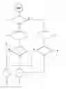
FIG. 1 shows a schematic flow chart for representing the method steps for detecting the clutch condition.
DETAILED DESCRIPTION
FIG. 1 shows a schematic flow chart of a method for clutch detection. It is checked in step 1 if wheel slip λ of at least one driven wheel is greater than a predefined threshold value λ0 and in addition if engine speed nMot is lower than a predetermined threshold value n0. If wheel slip λ is greater than threshold value λ0 and engine speed nMot is lower than threshold value n0, a drive torque pulse is generated (step 2). If, on the other hand, at least one of the named conditions is not met (case N), a drag torque pulse is generated in step 3.
After step 2, it is monitored in step 4 if the change in engine speed occurs at a characteristic rate of increase as is typical for the disengaged condition and how wheel speeds nRad behave in comparison to this. If the response of the engine to the pulse shows a curve typical for the disengaged condition and the wheel speeds do not change or change only slightly, a disengaged condition is detected in step 7. If, on the other hand, at least one of the conditions in step 4 is not met, the engaged condition is detected (step 6).
After a drag torque is exerted in step 3, it is again monitored in step 5 if the engine speed drops at a predefined rate of increase which is typical for the disengaged condition and how the wheels behave in comparison to this. If engine speed nMot follows a characteristic curve in which the wheel speeds do not change or change only slightly, a disengaged condition is detected in step 7. If, however, the behavior of the wheels correlates strongly with the engine speed, an engaged condition is detected (step 6).
A control unit is preferably used for the automatic generation of an engine torque pulse and the evaluation of the rotational speed values.
With the aid of the method described above, it is possible in a simple manner, even in extreme driving situations such as, for example, ABS braking, to determine an engaged or disengaged condition of the clutch.
Claims
What is claimed is:1. A method for detecting a clutch condition in an engine-powered vehicle, comprising:
increasing or reducing automatically by pulses an engine torque of at least one vehicle engine; and
evaluating a response of the engine to a torque pulse.
2. The method according to claim 1, wherein wheel speeds of at least one driven wheel are measured in addition and a correlation between a change in the engine torque and a change in the wheel speed are considered after a torque pulse is output.
3. The method according to claim 2, wherein the clutch condition “engaged” is detected if a correlation is greater than a predefined threshold value.
4. The method according to claim 2, wherein the condition “disengaged” is detected if a correlation is lower than a predefined threshold value.
5. The method according to claim 1, wherein the torque pulse has a fixed value.
6. The method according to claim 5, wherein the torque pulse is between 10 Nm and 40 Nm.
7. The method according to claim 1, wherein a wheel slip of at least one driven wheel and/or an engine speed is monitored, and a drive torque pulse or a drag torque pulse is exerted as a function of a degree of the wheel slip and/or the engine speed.
8. The method according to claim 7, wherein a drive torque pulse is triggered if the wheel slip is greater than a first predefined threshold value and the engine speed is lower than a second predefined threshold value, and a drag torque pulse is triggered if the wheel slip is lower than the first threshold value or the engine speed is greater than the second threshold value.
9. A control unit for detecting a clutch condition in an engine-powered vehicle, comprising:
means for increasing or reducing automatically by pulses an engine torque of at least one vehicle engine; and
means for evaluating a response of the engine to a torque pulse.
Images & Drawings included:
Sources:
- United States Patent and Trademark Office - verify current appl. status at the USPTO↗
Recent applications in this class:
- » 20250180081 2025-06-05
CLUTCH CONTROL DEVICE - » 20250172179 2025-05-29
METHOD FOR CALIBRATING A CLUTCH CONTROL - » 20250163977 2025-05-22
DOG CLUTCH CONTROL SYSTEM - » 20250137502 2025-05-01
METHOD FOR CONTROLLING AN OPERATION OF A MOTOR VEHICLE - » 20250084903 2025-03-13
METHOD FOR CHECKING THE ACTUATING ACCURACY OF A CLUTCH WHEN AN ELECTRIC OR HYBRID MOTOR VEHICLE IS AT A STANDSTILL - » 20250084902 2025-03-13
CLUTCH CONTROL DEVICE - » 20250020176 2025-01-16
Method For Determining A Force Transmission Contact Point Of An Electric Clutch Actuator - » 20240392846 2024-11-28
METHOD AND DEVICE FOR CALIBRATING A CLUTCH, AND AGRICULTURAL TOWING VEHICLE - » 20240288037 2024-08-29
CONTROLLER OF VEHICLE, VEHICLE INCLUDING CONTROLLER, AND METHOD OF CONTROLLING VEHICLE - » 20240151279 2024-05-09
METHOD FOR STANDSTILL CONTROL OF A MULTI-BODY SYSTEM
Recent applications for this Assignee:
- » 20250154889 2025-05-15
PRESSURE CONTROL IN AN EXHAUST AFTERTREATMENT SYSTEM - » 20250154580 2025-05-15
ENZYME TRANSLOCATORS IN NANOGAP WITH 3' -ESTERS - » 20250147582 2025-05-08
METHOD FOR DETERMINING AN EYE DISTANCE IN A PAIR OF DATA GLASSES, AND DATA GLASSES - » 20250146568 2025-05-08
DRIVE ASSEMBLY AND VEHICLE HAVING SUCH A DRIVE ASSEMBLY - » 20250146495 2025-05-08
Flexible Pump Assembly for Use in a Fan Drive - » 20250140882 2025-05-01
FUEL CELL SYSTEM HAVING ENERGY RECUPERATION - » 20250137810 2025-05-01
METHOD FOR MATCHING A DIGITAL ROAD MAP - » 20250137033 2025-05-01
DNA UNFOLDING USING A FREE-END TAG FLOW MODIFIER - » 20250119751 2025-04-10
A BLUETOOTH COMMUNICATION METHOD AND SYSTEM - » 20250118116 2025-04-10
Diagnostic Protocol Search With Improved Efficiency