Anti-Vibration Fan
US20120063886A1
2012-03-15
13/209,466
2011-08-15
Abstract:
The fan of the invention includes a frame and a vibration absorber. The frame has a fixing recess at a corner thereof. The vibration absorber has an elastic body fastened in the fixing recess and a pin with a circular trough. A portion of the elastic body protrudes from the frame. The pin is fixed at the portion of the elastic body for fastening the frame on a panel.
Interested in similar patents?
Get notified when new applications in this technology area are published.
Classification:
H05K7/20172 » CPC main
Constructional details common to different types of electric apparatus; Modifications to facilitate cooling, ventilating, or heating using a gaseous coolant in electronic enclosures; Forced ventilation, e.g. by fans Fan mounting or fan specifications
H05K7/20172 » CPC main
Constructional details common to different types of electric apparatus; Modifications to facilitate cooling, ventilating, or heating using a gaseous coolant in electronic enclosures; Forced ventilation, e.g. by fans Fan mounting or fan specifications
F04D25/0613 » CPC further
Pumping installations or systems; Units comprising pumps and their driving means the pump being electrically driven the electric motor being specially adapted for integration in the pump the electric motor being of the inside-out type, i.e. the rotor is arranged radially outside a central stator
F04D29/668 » CPC further
Details, component parts, or accessories; Combating cavitation, whirls, noise, vibration or the like ; Balancing especially adapted for elastic fluid pumps damping or preventing mechanical vibrations
G06F1/183 » CPC further
Details not covered by groups - and; Constructional details or arrangements; Packaging or power distribution Internal mounting support structures, e.g. for printed circuit boards, internal connecting means
G06F1/20 » CPC further
Details not covered by groups - and; Constructional details or arrangements Cooling means
F04D29/66 IPC
Details, component parts, or accessories Combating cavitation, whirls, noise, vibration or the like ; Balancing
Description
BACKGROUND OF THE INVENTION
1. Technical Field
The invention relates to fans, particularly to fans for heat dissipation.
2. Related Art
Heat dissipation devices are very important to modern electronic apparatuses. Usually, a fan is applied in a heat dissipation device to take heat away or make air flow. However, a fan vibrates when operating. The vibration of a fan will generate noise and make the screws which fasten the fan loosen.
A conventional solution against vibration is to use a rubber washer between a fan and a mount panel. But the rubber washer is not very easy when assembling because the rubber washer must be aligned with a screw.
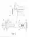
Another conventional solution is shown in FIG. 1, in which a rubber pin 30 and a rubber washer 40 are used. The rubber pin 30 is formed with two expanded cones 34 to divide into three sections 31, 32, 33. The bottom 341 of the cone 34 forms a supporting surface to support two opposite sides of a fan 60 by inserting the pin 30 into a hole 601 of the fan 60. The rubber washer 40 is located between the fan 60 and a mount panel 50. Thus the rubber pin 30 and rubber washer 40 can absorb the vibration of the fan 60.
However, in the above structure, the rubber pin is too thin to have enough strength. Thus the rubber pin tends to be broken when assembling.
SUMMARY OF THE INVENTION
An object of the invention is to provide an anti-vibration fan, which has sufficiently structural strength and can be easily assembled or disassembled.
To accomplish the above object, the fan of the invention includes a frame and a vibration absorber. The frame has a fixing recess at a corner thereof. The vibration absorber has an elastic body fastened in the fixing recess and a pin with a circular trough. A portion of the elastic body protrudes from the frame. The pin is fixed at the portion of the elastic body for fastening the frame on a panel.
BRIEF DESCRIPTION OF THE DRAWINGS
FIG. 1 is a cross-sectional view of a conventional fan with vibration absorption;
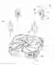
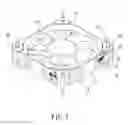
FIG. 2 is an exploded view of the invention;
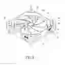
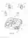
FIG. 3 is a perspective view of the invention;
FIG. 4 is a schematic view showing the invention is fixed on a panel of a computer;
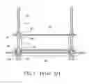
FIG. 5 is a side view of the invention;
FIG. 6 is a side view of the invention fixed on a panel;
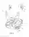
FIG. 7 is a perspective view of another embodiment of the invention;
FIGS. 8, 9 and 10 show still another embodiment of the invention; and
FIG. 11 shows the still another embodiment fixed on a panel.
DETAILED DESCRIPTION OF THE INVENTION
Please refer to FIGS. 2 and 3. The invention includes a fan 10 and four vibration absorbers 20. The fan 10 is composed of a frame 11 and a fan core 101. Four corners of the frame 11 are separately formed with four fixing recesses 12. Each of the fixing recesses 12 is provided with two protrusion 121 at an opening thereof and two bars 122 on the inside thereof. In fact, one bar 122 is also available.
Each of the vibration absorbers 20 is composed of an elastic body 25 made of plastic, rubber or silicone and two pins 21 which oppositely protrude from the elastic body 25. Each of the pins 21 is formed with a circular trough 22 which abuts against the elastic body 25. The surface of the elastic body 25 is formed with two alcoves 23 corresponding to the protrusions 121 and two slots 24 corresponding to the bars 122. The elastic body 25 is fastened in the fixing recess 12 by embedding the protrusions 121 and the bars 122 into the alcoves 23 and slots 24, respectively.
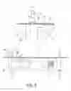
Please refer to FIG. 4. The fan 10 of the invention may be fixed on a panel 91 of an electronic device such a computer 90. There are holes 92 in the panel 91 for being penetrated by the pins 21. The panel 91 is nipped in the circular trough 22 to fasten the fan 10 on the panel 91.
Please refer to FIGS. 5 and 6. The ends of the elastic body 25 protrude from the frame 11. That is to say, the height of the elastic body 25, which is annotated as H1, is larger than the height of the frame 25, which is annotated as H2. The height difference will make a gap between the panel 91 and the frame 25. In other words, the frame 25 is not in direct contact with the panel 91. The vibration caused by the fan 10 will be absorbed by the elastic body 25 but not be transferred to the panel 91.
The frame 11 is provided with a lamp 13, which may be an LED. The lamp 13 may light up the fan core 101.
FIG. 7 shows another type of the fan core 101.
Please refer to FIGS. 8, 9, 10 and 11, which show another embodiment of the invention. The elastic body 25 is formed with a protrudent seat 201. The pin 21 is fixed on the protrudent seat 201. The outer end of the protrudent seat 201 protrudes from the frame 11 and the circular trough 22 is located on the pin 21 and near the protrudent seat 201. The panel 91 to be fastened by the fan 10 can be nipped in the circular trough 22 and abut against the protrudent trough 201.
Claims
What is claimed is:1. An anti-vibration fan comprising:
a frame, having a fixing recess at a corner thereof;
a vibration absorber, having an elastic body fastened in the fixing recess and a pin with a circular trough;
wherein a portion of the elastic body protrudes from the frame, and the pin is fixed at the portion of the elastic body.
2. The anti-vibration fan of claim 1, wherein the elastic body is made of plastic, rubber or silicone.
3. The anti-vibration fan of claim 1, wherein the fixing recesses is provided with two protrusion at an opening thereof, and the elastic body is formed with two alcoves being embedded by the protrusions.
4. The anti-vibration fan of claim 1, wherein the fixing recess is provided with a bar, and the elastic body is formed with a slot being embedded by the bar.
5. The anti-vibration fan of claim 1, wherein the elastic body is formed with a protrudent seat, the pin is fixed on the protrudent seat, an outer end of the protrudent seat protrudes from the frame, and the circular trough is located on the pin and near the protrudent seat.
Images & Drawings included:


Sources:
- United States Patent and Trademark Office - verify current appl. status at the USPTO↗
Similar patent applications:
- » 20080175705
Frame Structure For Anti-Vibration Fan - » 20230368763
Anti-Vibration Fan Mounting Gasket - » 20130195622
Anti-vibration serial fan structure - » 20100129235
ANTI-VIBRATION STRUCTURE FOR COOLING FAN
Recent applications in this class:
- » 20250169025 2025-05-22
SLIDABLY PLUGGABLE MULTI-FAN MODULE AND SERVER COMPRISING SAME - » 20250169024 2025-05-22
Server System Fan System - » 20250151226 2025-05-08
HEAT DISSIPATION DEVICE AND COMPUTER DEVICE - » 20250142767 2025-05-01
LOW-NOISE FAN FOR INFORMATION HANDLING SYSTEMS - » 20250142766 2025-05-01
FAN ASSEMBLY AND ELECTRONIC DEVICE - » 20250133689 2025-04-24
CONTROL APPARATUS AND COOLING METHOD OF CONTROL APPARATUS - » 20250113463 2025-04-03
LASER LEVEL COOLING - » 20250113462 2025-04-03
CONFIGURABLE AIRFLOW DIRECTION FAN SYSTEM - » 20250113461 2025-04-03
Server Information Handling System with Reversible Airflow Fan System - » 20250107034 2025-03-27
DEVICE FOR COOLING ELECTRONIC EQUIPMENT