Installation and method for the production of cold and/or heat
US20120067067A1
2012-03-22
13/257,676
2010-03-25
✅ Patent granted
US 9,599,371 B2
2017-03-21
WO; PCT/FR2010/050543; 20100325
WO; WO2010/109143; 20100930
Frantz Jules | Steve Tanenbaum
Sofer & Haroun, LLP
2033-05-14
Abstract:
An installation for the production of cold and/or heat has a driving and a receiving machine. The driving machine has means for circulating a working fluid GM, an evaporator EM, at least one transfer cylinder CTM that contains a transfer liquid LT in a lower part and the working fluid GM liquid and/or vapor form above the transfer liquid, a condenser CM, at least one device BSM for separating the liquid and vapor phases of the working fluid GM, and a device for compressing the working fluid GM to the liquid state. The receiving machine has means for circulating a working fluid GR, a condenser CR, at least one device BSR for compressing or expanding and separating the liquid and vapor phases of the working fluid GR, optionally a pressure reducer DR, an evaporator ER and at least one transfer cylinder CTR that contains the transfer liquid LT in a lower portion and the working fluid GR in liquid and/or vapor form above the transfer liquid; the transfer cylinders CTR and CTM are connected by at least one pipe that can be blocked by actuators and in which only the transfer liquid LT can circulate.
Inventors:
- Sylvain MAURAN 5 🇫🇷 Millas, France
- Nathalie MAZET 9 🇫🇷 Perpignan, France
- Pierre Neveu 1 🇫🇷 Michel de Llotes, France
- Driss Stitou 2 🇫🇷 Nazaire, France
- Driss Stitou 8 🇫🇷 St Nazaire, France
Assignee:
- CENTRE NATIONAL DE LA RECHERCHE SCIENTIFIQUE 3,102 🇫🇷 PARIS, France
Applicant:
Interested in similar patents?
Get notified when new applications in this technology area are published.
Classification:
F25B13/00 IPC
Compression machines, plants or systems, with reversible cycle
F01K25/08 » CPC further
Plants or engines characterised by use of special working fluids, not otherwise provided for; Plants operating in closed cycles and not otherwise provided for using special vapours
F25B27/005 » CPC further
Machines, plants or systems, using particular sources of energy using solar energy in compression type systems
F02G2250/09 » CPC further
Special cycles or special engines Carnot cycles in general
F24H2240/125 » CPC further
Fluid heaters having electrical generators with thermodynamic cycle for converting thermal energy to mechanical power to produce electrical energy Carnot cycles
F25B27/00 IPC
Machines, plants or systems, using particular sources of energy
F25B1/02 » CPC main
Compression machines, plants or systems with non-reversible cycle with compressor of reciprocating-piston type
F25B29/003 » CPC further
Combined heating and refrigeration systems, e.g. operating alternately or simultaneously of the compression type system
F25D17/02 IPC
Arrangements for circulating cooling fluids; Arrangements for circulating gas, e.g. air, within refrigerated spaces for circulating liquids, e.g. brine
F25B7/00 IPC
Compression machines, plants or systems, with cascade operation, i.e. with two or more circuits, the heat from the condenser of one circuit being absorbed by the evaporator of the next circuit
F01K23/06 IPC
Plants characterised by more than one engine delivering power external to the plant, the engines being driven by different fluids the engine cycles being thermally coupled combustion heat from one cycle heating the fluid in another cycle
F01K13/00 IPC
General layout or general methods of operation of complete plants
F02G1/04 IPC
Hot gas positive-displacement engine plants of closed-cycle type
F25B29/00 IPC
Combined heating and refrigeration systems, e.g. operating alternately or simultaneously
Description
The present invention relates to an installation for the production of cold and/or heat.
TECHNOLOGICAL BACKGROUND
Thermodynamic machines used for the production of cold, heat, or energy all relate to an ideal machine referred to as a Carnot machine. An ideal Carnot machine requires a heat source and a heat sink at two different temperature levels. It is therefore referred to as a dithermal machine. It is referred to as a driving Carnot machine when it operates no provide work and as a receiving Carnot machine (also known as a Carnot heat pump) when it operates by consuming work. In heat-engine mode, heat Qh is supplied to a working fluid GT from a hot source at the temperature Th, heat Qb is ceded by the working fluid GT to a cold sink at the temperature Tb, and net work W is delivered by the machine. Conversely, in heat-pump mode, heat Qb is taken up by the working fluid GT from the cold source at the temperature Tb, heat Qh is ceded by the working fluid to the heat sink at the temperature Th, and net work W is consumed by the machine.
According to the second law of thermodynamics, the efficiency of a dithermal (driving or receiving) machine, i.e. a real machine whether operating according to the Carnot cycle or not, is at most equal to that of the ideal Carnot machine and depends only on the source temperature and the sink temperature. However, practical implementation of the Carnot cycle, consisting of two isothermal steps (at the temperatures Th and Tb) and two reversible adiabatic steps, encounters several problems that have not been completely solved until now. During the Carnot cycle the working fluid may remain in the gaseous state at all times or it may undergo a liquid/vapor change of state during the isothermal transformations at the temperatures Th and Tb. When a liquid/vapor change of state occurs, heat is transferred between the machine and the environment with greater efficiency than if the working fluid remains in the gaseous state. With a change of state, and for the same thermal powers exchanged at the level of the heat source and the heat sink, the exchange areas are smaller (and therefore less costly). However, if there is a liquid/vapor change of state, the reversible adiabatic steps consist in compressing and expanding a two-phase liquid/vapor mixture. Prior art techniques are unable to compress or expand two-phase mixtures. In the present state of the art, it is not known how to carry out these transformations correctly.
To solve this problem, approximating the Carnot cycle has been envisaged by isentropically compressing a liquid and isentropically expanding a superheated vapor (driving cycle) and compressing the superheated vapor and isenthalpically expanding the liquid (receiving cycle). However, such modifications introduce irreversibilities into the cycle and greatly degrade its efficiency, i.e. the efficiency of the heat engine or the coefficient of performance or the coefficient of amplification of the heat pump.
So called “absorption”, “adsorption”, and “chemical reaction” methods have been developed for the production of cold at the temperature Th and/or heat at an intermediate temperature Tm essentially using heat at a high temperature Th as an external energy source, plus a little work, in particular to circulate the heat-exchange fluids. If the function of the method is the production of cold, its efficiency is quantified by a coefficient of performance COP3, which is the ratio of the cold produced to the ‘costly’ energy consumed (heat at high temperature and work). When the function of the method is the production of heat at a useful temperature Tm, its efficiency is quantified by a coefficient of amplification COA3, which is the ratio of heat delivered at the temperature Tm to the ‘costly’ energy consumed (heat at high temperature and work).
The combination of a Carnot driving machine operating between temperatures ThM and TbM and a Carnot receiving machine operating between temperatures TbR and ThR could provide the same functions as said absorption, adsorption, or chemical reaction methods providing all the work supplied by the Carnot driving machine is recovered by the Carnot receiving machine. In the general case, the temperatures TbM, TbM, TbR, and TbR are different and the combination of the two Carnot machines is referred to as a “quadrithermal Carnot machine”. However, some temperatures may be the same (TbM=ThR=Tm or TbM=TbR=Tm), in which case the combination of the two Carnot machines is referred to as a “trithermal Carnot machine”.
The coefficient of performance or the coefficient of amplification of any trithermal or quadrithermal process is at best equal to the coefficients (CPPC3, COPC4, COAC3, or COAC4) of trithermal or quadrithermal Carnot machines operating between the same temperature levels, and is generally lower.
In the current state of the art, absorption, adsorption, or chemical reaction processes in practice have efficiencies much lower than those of corresponding trithermal or quadrithermal Carnot machines. The ratios COP3/COPn are typically of the order of 0.3.
Furthermore, many absorption, adsorption, or chemical reaction processes use water at low pressure (<10 kilopascals (kPa)) as the working fluid, which requires a perfect seal from the external environment and leads to solutions that are technically difficult to implement in order to integrate the various elements of the machine in the same low-pressure enclosure.
The Present Invention
The object of the present invention is no provide a trithermal or quadrithermal thermodynamic installation operating in accordance with a cycle close to the Carnot cycle, and that is improved relative to prior art installations, i.e. that functions with a liquid/vapor change of state of the working fluids to preserve the advantage of the small areas of contact required, at the same time as significantly limiting irreversibilities in the driving and receiving cycles of the trithermal or quadrithermal installation during the adiabatic steps, which implies better efficiencies COP/COPC or COA/COAc.
The present invention firstly provides an installation for the production of cold and/or heat. It also provides a method of producing cold and/or heat using said installation.
A trithermal or quadrithermal installation of the present invention for the production of cold and/or heat comprises a driving machine and a receiving machine, and is characterized in that:
a) the driving machine comprises both means comprising pipes and actuators for causing a working fluid GM to circulate and also, in the order of circulation of said working fluid GM:
-
- an evaporator EM;
- at least one transfer cylinder CTM that contains a transfer liquid LT in a lower portion and the working fluid GM in liquid and/or vapor form above the transfer liquid;
- a condenser CM;
- at least one device BSM for separating the liquid and vapor phases of the working fluid GM; and
- a device for pressurizing the working fluid GM in the liquid state;
b) the receiving machine comprises both means comprising pipes and actuators for causing a working fluid GR to circulate and also, in the order of circulation of said working fluid GR:
-
- a condenser CR;
- at least one device BSR for pressurizing or expanding and separating the liquid and vapor phases of the working fluid GR:
- optionally a pressure reducer DR;
- an evaporator ER; and
- at least one transfer cylinder CTR that contains the transfer liquid LT in a lower portion and the working fluid GR in liquid and/or vapor form above the transfer liquid; and
c) the transfer cylinders CTR and CTM are connected by at least one pipe that may be blocked by actuators and in which only the transfer liquid LT may circulate.
The actuators may be valves.
The pressurization device is advantageously a hydraulic pump PH.
The method of producing cold or heat using an installation of the present invention consists in causing a working fluid GM to undergo a succession of modified. Carnot cycles in the driving machine of the installation and it is characterized in that each cycle of the driving machine is initiated, by input of heat to the evaporator EM and initiates a modified Carnot cycle in the receiving machine by transfer of work by means of the transfer liquid LT between at least one transfer cylinder of the driving machine and at least one transfer cylinder of the receiving machine. When the installation is in use, each evaporator is connected to a heat source and each condenser is connected to a heat sink, for example via heat exchangers. Each of the evaporators EM and ER is connected to a heat source, respectively at the temperature ThM for the evaporator EM and the temperature TbR for the evaporator ER. Each of the condensers CM and CR is connected to a heat sink, respectively at the temperature TbM for CM and the temperature ThR for CR. These temperatures are such that TbM<ThM and TbR<ThR.
In the present text:
-
- “dithermal modified Carnot cycle” means a thermodynamic cycle comprising the steps of the theoretical Carnot driving or receiving cycle or similar steps with a degree of reversibility less than 100%;
- “quadrithermal installation” means an installation that has the above features a), b), and c) in which the temperatures ThM, TbM, ThR, and TbR are different;
- “trithermal installation” means an installation that has the above features a), b), and c) in which either the temperatures TbM and ThR are identical and the temperatures TbM and TbR are different or the temperatures TbM and TbR are identical and the temperatures TbM and ThR are different;
- “environment” means any element external to the trithermal or quadrithermai installation as defined by the above features a), b), and c); the environment comprises in particular the heat sources and heat sinks and any heat exchangers;
- “reversible transformation” means a transformation that is reversible in the strict sense, as well as a quasi-reversible transformation; the sum of the entropy variations of the fluid that undergoes the transformation and of the environment, is zero during a strictly reversible transformation corresponding to the ideal situation and slightly positive during a real, quasi-reversible transformation; the degree of reversibility of a cycle, which in practice is less than 1, may be quantified by the ratio between the efficiency (or the coefficient of performance COP or the coefficient of amplification COA) of the cycle and that of the Carnot cycle operating between the same extreme temperatures; the higher the reversibility of the cycle, the closer this ratio is to 1.
- “isothermal transformation” means a transformation that is strictly isothermal or occurs under conditions close to the theoretical isothermal conditions, given that, under real conditions of implementation, during a transformation considered as isothermal and effected cyclically, the temperature T is subject to slight variations ΔT/T, for example ±10%; and
- “adiabatic transformation” means a transformation with no exchange of heat with the environment, or with exchanges of heat minimized by thermally insulating from the environment the fluid that undergoes the transformation.
- “dithermal modified Carnot cycle” means a thermodynamic cycle comprising the steps of the theoretical Carnot driving or receiving cycle or similar steps with a degree of reversibility less than 100%;
A driving dithermal modified Carnot cycle comprises the following successive transformations:
-
- an isothermal transformation with exchange of heat between the working fluid GM and the heat source at the temperature ThM;
- an adiabatic transformation with reduction of the pressure of the working fluid GM;
- an isothermal transformation with exchange of heat between the working fluid GM and the heat sink at the temperature TbM; and
- an adiabatic transformation with an increase in the pressure of the working fluid GM.
A dithermal modified Carnot receiving cycle comprises the following successive transformations:
-
- an isothermal transformation with exchange of heat between the working fluid GR and the heat source at the temperature TbR;
- an adiabatic transformation with an increase in the pressure of the working fluid GR;
- an isothermal transformation with exchange of heat between the working fluid GM and the heat sink at the temperature ThR; and
- an adiabatic transformation with a reduction in the pressure of the working fluid GM.
If the temperature Thm is above the temperature ThR, the trithermal or quadrithermal installation operates in the so-called “HT driving/LT receiving” mode. FIG. 1a is a theoretical diagram of this implementation. In this first situation, the target application is the production of cold at the temperature TbR below ambient temperature and/or the production of heat (with COA >1) at the temperatures ThR and TbM above ambient temperature.
If temperature ThM is below temperature ThR, the trithermal or quadrithermal installation operates in the so-called. “LT driving/HT receiving” mode. FIG. 1b is a theoretical diagram of this implementation. In this second situation, the target application is the production of heat at the temperature ThR above those of the two heat sources at the temperatures ThR and ThM (which may be the same), but with a coefficient of amplification (ratio of the heat delivered as the temperature ThR to the heat consumed at the temperatures TbR and ThM) less than unity.
The method of the present invention is more particularly implemented in an installation of the present invention from an initial state in which:
-
- the driving machine and the receiving machine are not connected to each other;
- in each of the machines, the actuators allowing communication between their different components are not activated;
- the temperature of the installation as a whole and in particular of the working fluids GM and GR that it contains is equal to ambient temperature; and
- the transfer liquid LT in the driving and receiving transfer cylinders (CTM and CTR) is at intermediate levels between the minimum and maximum levels in she cylinders; and
the method comprises a succession of modified. Carnot cycles.
The first cycles constitute the starting stage for reaching steady conditions. The successive actions carried out during each cycle of the starting stage are the same as those of steady conditions, hut their effects vary progressively from one cycle to the next until steady conditions are obtained, with this applying in particular to the values of the temperatures and of the pressures of the working fluids GM and GR and to the temperatures of the heat-exchange fluids exchanging heat with the heat sources and the heat sinks.
The actions carried out during the starting stage and that involve exchanges with the heat sources and the heat sinks depend on the operating mode selected, namely “HT driving/LT receiving” or “HT receiving/LT driving”. Moreover, in the “HT driving/LT receiving” mode, they also depend on the target application, namely production of cold or production of heat.
If the operating mode of the trithermal or quadrithermal installation is “HT driving/LT receiving” and the target application is the production of cold at a temperature TbR below ambient temperature, the first cycle of the starting stage is constituted by:
-
- a first step that consists in executing the following actions simultaneously:
- establishing thermal communication via a heat-exchange fluid between the hot source at the temperature ThM and the evaporator EM, the consequence of which is to increase the temperature and the saturated vapor pressure of the working fluid GM in the evaporator EM;
- establishing communication between the transfer cylinder CTM and the evaporator EM, the consequence of which is to evaporate the working fluid GM in the evaporator EM and to transfer the working fluid GM in the vapor state from the evaporator EM to the transfer cylinder CTM;
- establishing communication between the device BSM and the evaporator EM, the consequence of which is to transfer liquid working fluid GM from the device BSM to the evaporator EM;
- establishing communication between the transfer cylinders CTM and CTR, the consequence of which is to transfer the transfer liquid LT from the transfer cylinder CTM to the transfer cylinder CTR and to compress the vapors of the working fluid GM contained in the transfer cylinder CTR; and
- establishing communication between the transfer cylinder CTR and the condenser CR, the consequence of which is to transfer vapors of the working fluid GR from the transfer cylinder CTR to the condenser CR, to condense said vapors in the condenser CR (requiring evacuation of heat to the heat sink initially at ambient temperature but gradually reaching a nominal value ThR above or below ambient temperature), and to cause condensates to accumulate in the device BSR;
- a second step that applies mainly to the driving machine and that consists in executing the following actions simultaneously:
- stopping circulation of the working fluid GM in the driving machine, stopping circulation of the working fluid GR in the receiving machine, and maintaining circulation of the heat-exchange fluids exchanging heat with the heat source at the temperature ThM and the heat sinks at the temperatures ThR and TbM; and
- establishing communication between the transfer cylinder CTM and the condenser CM, the consequence of which is to transfer the working fluid GM from the transfer cylinder CTM to the condenser CM, to reduce the pressure of the working fluid GM in the transfer cylinder CTM, to condense the working fluid GM in the condenser CM (requiring evacuation of heat to the heat sink initially at ambient temperature but gradually reaching a nominal value TbM above or below ambient temperature), and to cause condensates to accumulate in the device BS;
- a third step that consists in executing the following actions simultaneously:
- establishing communication between the device BSR and the evaporator ER, the consequence of which is to transfer a portion of the liquid working fluid GR from the device BSR to the evaporator ER, the vapor pressure of the working fluid GR in the evaporator ER then being greater than that in the transfer cylinder CTM; and
- establishing communication between the transfer cylinders CTR and CTM, the consequences of the quasi-instantaneous balancing of pressures that occurs in these two cylinders being:
- to transfer the transfer liquid LT from the transfer cylinder CTR to the transfer cylinder CTM;
- to compress the vapors of the working fluid GM contained in the transfer cylinder CTM;
- to expand and endothermically evaporate the working fluid GR in the evaporator ER;
- to condense the vapors of the working fluid GM in the condenser CM (requiring evacuation of heat to the heat sink at the temperature TbM and to cause condensates of the working fluid GM to accumulate in the device BSM; and
- to reduce the temperature of the working fluid GR remaining in the liquid state in the evaporator ER to the saturation temperature for the resulting pressure after establishing communication between the transfer cylinder CTR and the transfer cylinder CTM;
- a fourth step that applies mainly to the receiving machine and that consists in executing the following actions simultaneously:
- stopping circulation of the working fluid GM in the driving machine, stopping circulation of she working fluid GR in the receiving machine, and maintaining circulation of the heat-exchange fluids exchanging heat with the heat source at the temperature ThM and the heat sinks at the temperatures ThR and TbM; and
- establishing communication between the device BSR and the transfer cylinder CTR, the consequence of which is to evaporate the working fluid CM in the device BSR, to transfer the working fluid GR from the device BSR to the transfer cylinder CTR, to increase the pressure of the working fluid GR in the transfer cylinder CTR, to exchange heat between the device BSR and the source at the temperature ThR, and to consume heat in the device BSR.
- a first step that consists in executing the following actions simultaneously:
In the above operating mode, circulation of the fluids may be controlled by actuators placed between the various components of the driving machine (for the working fluid GM) or between the various components of the receiving machine (for the working fluid GR). The actuators may advantageously be; valves, possibly coupled to a pressurization device such as a hydraulic pump, for example (notably a device placed between the device BSM and the evaporator EM of the driving machine) or a pressure reducer (notably between the device BSM and the evaporator ER of the receiving machine).
At the end of this first cycle, the level of the liquid LT in the transfer cylinder CTM is at a maximum and the level of the liquid. LT in the transfer cylinder CTR is at a minimum, the temperature of the working fluid GM is close to the temperature ThM in the evaporator EM, but still below the temperature ThM, and close to the temperature TbM in the condenser CM, but still above the temperature ThM, the temperature of the working fluid GR in the condenser CR and the device BSR is close to the temperature ThR and still above the temperature ThR, and the temperature of the working fluid GR in the evaporator ER is below its initial temperature. Each cycle induces a reduction in the temperature of the working fluid GR in the evaporator ER. When the temperature of the working fluid GR in the evaporator ER reaches a value close to and below the temperature TbR, the starting stage is finished and the heat-exchange fluid is caused to circulate in the evaporator ER, which then produces cold at the temperature TbR. Steady conditions have been reached. The subsequent cycles of the trithermal or quadrithermal installation are identical to the starting cycles (starting from the second) except that all of the heat sources and heat sinks are then connected.
If the operating mode of the trithermal or quadrithermal installation is “HT driving/LT receiving” and the target application is the production of heat at the temperatures TbM and ThR (which may be the same) above ambient temperature, given that heat sources are available at the temperatures ThM and TbR, the starting stage of said machine is similar to the starting stage described above. The difference relates only to the transient stage of establishing the temperature before connecting the heat-exchange fluid. In the previous situation this transient stage applies to the working fluid GR in the evaporator ER, while in the present situation it applies to the working fluid GR in the condenser CR and the working fluid GM in the condenser CM.
In the same way, if the operating mode of the trithermal or quadrithermal installation is “HT receiving/LT driving” and the target application is the production of heat at the temperature ThR above the heat source temperatures TbR and ThM (which may be the same), using a heat sink at the temperature ThM, the starting stage of said machine is similar to the starting stage described above except that the transient stage of establishing the temperature ThR before connecting the heat-exchange fluid applies to the working fluid GR in the condenser CR.
The working fluid GT (interchangeably designated GR or GM) and the transfer liquid LT are chosen so that the working fluid GT is weakly soluble, preferably insoluble in the liquid LT, so that the working fluid GT does not react with the liquid LT and so that the working fluid GT in the liquid state is less dense than the liquid LT. If the solubility of the working fluid GT in the liquid LT is too high or if the working fluid GT in the liquid state is more dense than the liquid LT, it is necessary to isolate them from each other by means that do not prevent the exchange of work between the cylinders CTM and CTR. Said means may consist for example in a flexible membrane disposed between the working fluid GT and the liquid LT, said membrane creating an impermeable barrier between the two fluids but opposing only very low resistance to movement of the transfer liquid and low resistance to the transfer of heat. Another solution consists in a float that has an intermediate density between that of the working fluid GT in the liquid state and that of the transfer liquid LT. A float may constitute a large material, barrier but is difficult to make perfectly efficient if it is desirable so avoid friction on the lateral wall of the transfer cylinders CT and CT′. In contrast, the float may constitute a highly efficient thermal resistance. The two solutions (membrane and float) may be combined.
FIG. 2a shows a transfer cylinder CT containing a transfer liquid LT and a working fluid GT that are not miscible, the liquid LT be more dense than the working fluid GT in the liquid state. The pipe 1 allows exit or entry of the transfer liquid, the pipes 2 and 3 allow entry and exit of the working fluid GT, and there is a thermally-insulative coating 4.
FIG. 2b shows a transfer cylinder in which the transfer liquid LT and the condenser CT are separated by a flexible membrane 5 fastened to the upper part of the cylinder, for example by a clamp 6.
FIG. 2c shows a transfer cylinder in which the liquid LT and the working fluid GT are separated by a float 7.
The transfer liquid. LT is chosen from liquids that have a low saturated vapor pressure at the operating temperature of the installation in order, in the absence of any separator membrane as described above, to avoid limitations caused by the diffusion of vapor from the working fluid GT through the vapor of the liquid. LT in the condenser or the evaporator. Subject to compatibility with the working fluid GT as referred to above, and by way of non-exhaustive example, the liquid LT may be water or a mineral or synthetic oil, preferably having a low viscosity.
The working fluid GT undergoes transformations in a thermodynamic range of temperature and pressure that is preferably compatible with liquid/vapor equilibrium, i.e. between the melting point and the critical temperature. However, during the modified Carnot cycle, some of these transformations may occur in whole or in part in the domain of the subcooled liquid or the superheated vapor or in the supercritical domain. A working fluid is preferably chosen from pure bodies and azeotropic mixtures in order to have a monovariant relation between temperature and pressure at liquid/vapor equilibrium. However, an installation of the invention may equally operate with a non-azeotropic solution as the working fluid.
The working fluid GT may be water, CO2, or NH, for example. The working fluid may further be chosen from alcohols having 1 to 6 carbon atoms, alkanes having 1 to 18 (more particularly 1 to 8) carbon atoms, chlorofluoroalkanes preferably having 1 to 15 (more particularly 1 to 10) carbon atoms, and partially or totally fluorinated, or chlorinated alkanes preferably having 1 to 15 (more particularly 1 to 10) carbon atoms. There may be mentioned in particular 1,1,1,2-tetrafluoroethane, propane, isobutane, n-butane, cyclobutane, and n-pentane. FIG. 3 plots the liquid/vapor equilibrium curves for a few of the above-mentioned working fluids GT. The saturated vapor pressure P (in bar) is plotted on a logarithmic scale up the ordinate axis as a function of the temperature T (in ° C.) plotted along the abscissa axis.
The working fluids GR and GM and the transfer liquid LT are generally chosen first as a function of the temperatures of the available heat sources and heat sinks in the machine, together with the maximum and minimum saturated vapor pressures required, then as a function of other criteria such as in particular toxicity, impact on the environment, chemical stability, and cost.
The working fluid GT in the transfer cylinder CTM or CTR may be in the two-phase liquid/vapor mixture state at the end of the adiabatic expansion step (modified dithermal Carnot driving cycle) or adiabatic compression step (modified dithermal Carnot receiving cycle). The liquid phase of the working fluid GT may then accumulate at the interface between the working fluid GT and the liquid LT. If the vapor content of the working fluid CT is high (typically in the range 0.95 to 1) in the transfer cylinder CTM or CTR before connecting said enclosure to the respective condenser CM or CR, total elimination of the liquid phase of the working fluid GT in these enclosures may be envisaged. Such elimination may be effected by maintaining the temperature of the working fluid GT in the transfer cylinder CTM or CTR at the ends of the steps of establishing communication between the transfer cylinder CTM or CTR and their respective condensers to a value above that of the working fluid GT in the liquid state in said condensers, so that there is no working fluid GT in the transfer cylinder CTM or CTR at this time.
In one particular embodiment, the installation comprises means for exchange of heat between firstly the heat sources and the heat sinks that are at different temperatures and secondly the evaporators, the condensers, and where appropriate the working fluid GT in the transfer cylinders CTM and CTR, so as to eliminate all risk of condensation of the working fluid GM in the transfer cylinder CTM or the working fluid GR in the transfer cylinder CTR. FIG. 4 shows one embodiment of a transfer cylinder that allows exchange of heat. Said cylinder comprises a double envelope 8 in which a heat-exchange fluid may circulate, with an inlet 9 and an outlet 10 for said heat-exchange fluid.
In the present text, a component comprising a transfer cylinder CTM and a transfer cylinder CTR is referred to as a CTM/CTR component.
In a first embodiment corresponding to a basic configuration, an installation of the present invention comprises a single CTM/CTR component.
In a second embodiment, an installation comprises two CTM/CTR components CTM/CTR and CTR′/CTR′.
In a third embodiment, an installation comprises two components CTM/CTR and CTM′/CTR′, two separate pressurization devices BSM1 and BSM2 for the driving machine, and two separate pressurization devices BSpd and BSR2 for the receiving machine.
FIG. 5 shows an example of an installation conforming to the basic configuration of the first embodiment (designated U0), i.e. comprising a single CTM/CTR component. In this example:
-
- the driving machine comprises
- a hydraulic pump PH for circulating the fluid in the liquid state;
- an evaporator EM connected to a heat source at the temperature ThM;
- a transfer cylinder CTM containing in a lower portion a transfer liquid LT and in an upper portion the driving working fluid GM;
- a condenser CM;
- a separator bottle BSM that recovers the condensates;
- solenoid valves EVc and EVd on the pipes between the transfer cylinder CTM and the evaporator EM and the condenser CM, respectively;
- a solenoid valve EVd between the separator bottle BSM and the hydraulic pump PH;
- the receiving machine comprises:
- an evaporator Ep;
- a transfer cylinder CTR containing in a lower portion the same transfer liquid LT and in an upper portion the receiving working fluid GR;
- a condenser CR;
- a separator bottle BSR that recovers the condensates and also has an evaporator function at the temperature ThR;
- a liquid pressure reducer D;
- solenoid valves EV1 and EV2 on the pipes between the transfer cylinder CTR and the evaporator ER and the condenser CR, respectively; and
- a solenoid valve EV3 between separator bottle BSR and the pressure reducer D; and
- the driving machine and the receiving machine are connected by a pipe connected to the lower portions of the transfer cylinders CTR and of CTM that may be blocked by the valve EVT.
- the driving machine comprises
In the FIG. 5 embodiment that corresponds to the basic configuration U0, each of the transfer cylinders shown is thermally insulated from the external environment and corresponds to FIG. 2a. It could be replaced by a cylinder maintained at a temperature sufficient to prevent condensation of the working fluid GM (or GR) in the transfer cylinder CTM (or CTR) in the form shown in FIG. 4.
The thermodynamic cycles undergone by the receiving working fluid GR and the driving working fluid GM in the variant U0 of the installation are shown in the Mollier diagram (FIGS. 6a and 6b, respectively), which plots the logarithm LnP of the pressure as a function of h (the enthalpy per unit mass of the fluid), and in the Clausius-Clapeyron diagram (FIGS. 5c and 6d), which plots LnP as a function of (−1/T). The relative position of the equilibrium straight line segments for the working fluid GM in the Clausius-Clapeyron diagram differ according to whether the operating mode of the trithermal or quadrithermal installation is “HT driving/LT receiving” (FIG. 5c) or “HT receiving/LT driving” (FIG. 5d).
An operating cycle of an installation as shown in FIG. 5 consists of four successive stages beginning at times tα, tβ, tγ, and tδ and that are described below in the context of the “HT driving/LT receiving” operating mode. A cycle is described for operation under steady conditions. Unless otherwise indicated, the solenoid valves are closed.
Stage αβ (Between Time tα and tβ)
At the moment immediately preceding time tα, the level of the transfer liquid LT is low (B) in the transfer cylinder CTR and high (H) in the transfer cylinder CTM and the saturated vapor pressure of the receiving and driving working fluids is low and equal to Pb in both cylinders. The configuration of the installation shown diagrammatically in FIG. 5 corresponds to this moment of the cycle.
At time tα, the valve EV2 is opened to establish communication between the cylinder CTR, the condenser CR, and the separator bottle BSR, in which the vapor pressure of the receiving working fluid GR is Ph. The pressure in the transfer cylinder CTR is then imposed rapidly by the liquid-vapor equilibrium of the working fluid GR, in the separator bottle BSR, which is then exercising the immersed evaporator function. The heat necessary to evaporate she working fluid GR in the separator bottle BSR is supplied at the temperature ThR. Between times tα and tβ, the working fluid CR contained in the transfer cylinder CTR undergoes the transformation 1→2 shown in FIGS. 6a and 6c.
Stage βγ (Between Times tβ and tγ)
At time tβ, i.e. when the pressure of the working fluid GR in the transfer cylinder CTR reaches the value Ph/the valve EV2 is left open and at the same time the solenoid valves EVa, EVc, EVT are opened and the pump PH is started. The consequences of this are:
In the driving circuit:
-
- The liquid working fluid GM is aspirated into the separator bottle BSM and propelled by the pump into the evaporator EM, where it evaporates, taking heat from the hot source at the temperature ThM. The flow rate at which the working fluid GM enters the evaporator is equal to the saturated vapor outlet flow rate, with the result that this evaporator remains filled at all times and retains a constant heat exchange efficiency. Since the saturated vapor of the working fluid GM occupies a greater volume than the working fluid GM in the liquid state, the transfer liquid in the transfer cylinder CTM is propelled downwards. During this stage βγ, the working fluid GM undergoes the transformations a a→b→b1→c plotted in FIGS. 6b and 6c. The heat necessary to heat the subcooled liquid (transformation b→b1) and then to evaporate the working fluid GM (transformation b1→c) is supplied by a heat source at the high temperature ThM. A small quantity of work Wab is consumed by the pump for the transformation a→b while a greater quantity of work Wh is transferred during the transformation b1→c to the receiving circuit via the transfer liquid LT exercising the liquid piston function.
In the receiving circuit:
-
- The transfer liquid LT in the transfer cylinder CTR is discharged at the high level (H), the saturated vapor of the working fluid GR condenses in the condenser CR, and the condensates accumulate in the separator bottle BSR. During this stage βγ the working fluid GR undergoes the transformation 2→21→3 plotted in FIGS. 6a and 6c. The condensation heat of the working fluid GR is delivered at the temperature T. There may be very slight or even no subcooling of the working fluid GR. If there is no subcooling, the points 21 and 3 in FIG. 6a coincide.
Stage γδ (Between Times tγ and tδ)
- The transfer liquid LT in the transfer cylinder CTR is discharged at the high level (H), the saturated vapor of the working fluid GR condenses in the condenser CR, and the condensates accumulate in the separator bottle BSR. During this stage βγ the working fluid GR undergoes the transformation 2→21→3 plotted in FIGS. 6a and 6c. The condensation heat of the working fluid GR is delivered at the temperature T. There may be very slight or even no subcooling of the working fluid GR. If there is no subcooling, the points 21 and 3 in FIG. 6a coincide.
At time tγ, the valves EVa, EVc, and EVT are closed and the valve EVd is opened. The vapor pressure of the driving working fluid GM falls rapidly from the value Ph to the value Pb imposed by the liquid-vapor equilibrium in the condenser CM. The condensation heat is evacuated at the temperature tbM and the condensates of the working fluid GM accumulate in the separator bottle BSM. Between times tγ and tδ, the working fluid GM contained in the transfer cylinder CTM undergoes the transformation c→d shown in FIGS. 6b and 6c.
Stage δα (Between Times tδ and tα)
At time tδ, i.e. when the pressure of the working fluid GM in the transfer cylinder CTM reaches the value Pb, the valve EV2 is closed, the valve EVd is left open, and at the same time the solenoid values EV1, EV3, and EVT are opened. The consequences of this are:
In the receiving circuit:
-
- The liquid working fluid GM is aspirated into the separator bottle BSR, expanded isenthalpically via the pressure reducer D (consisting of a capillary or a needle valve) and introduced in two-phase form into the evaporator ER, where it finally evaporates. The saturated vapor of the working fluid GR produced propels downward (B) the transfer liquid in the cylinder CTR. During this stage δα the fluid GR undergoes the transformations 3→4→1 plotted in FIGS. 6a and 6c. The heat necessary to evaporate the working fluid GR is taken at the low temperature TbR. Work Wb is transferred during the transformation 4→1 to the receiving circuit via the transfer liquid LT.
In the driving circuit:
-
- The transfer liquid LT in the transfer cylinder CTM is propelled upward (H), the saturated vapor of the working fluid GM condenses in the condenser CM, and the condensates accumulate in the separator bottle BSM. During this stage δ the working fluid GM undergoes the transformation d→a plotted in FIGS. 6b and 6c. The condensation heat of the working fluid GM is delivered at the temperature ThM. At the end of this stage, the installation is again in the state of the cycle.
The heart of the invention consists of the stages βγ and δα in the device for transferring work between the driving cycle and the receiving cycle via the transfer liquid LT exercising the liquid piston function.
The various thermodynamic transformations undergone by the working fluids GR and GM and the levels of the transfer liquid LT are summarized in Table 1. The states of the actuators (the solenoid valves and a clutch of the pump PH) are summarized in Table 2, in which an X signifies that the corresponding solenoid valve is open or that the clutch of the pump PH is engaged.
| TABLE 1 | ||
| LT level |
| Step | Transformations | Location | CTR | CTM | |
| αβ | 1 → 2 | BSR + CR + CTR | B | H | |
| βγ | a → b → bl → c | EM + CTM | H→B | ||
| 2 → 2l → 3 | BSR + CR + CTR | B→H | |||
| γδ | c → d | CTM | H | B | |
| δα | 3 → 4→ 1 | ER + CTR | H→B | ||
| d → a | CTM + CM | B→H | |||
| TABLE 2 | ||||||||
| Step | EV1 | EV2 | EV3 | EVa | EVc | EVd | EVT | PH |
| αβ | x | |||||||
| βγ | x | x | x | x | x | |||
| γδ | x | x | ||||||
| δα | x | x | x | x | ||||
In the basic configuration (U0) shown in FIG. 5, the production of cold at the temperature TbR occurs only during the stage δα while the consumption of heat at the temperature ThM occurs only during the stage βγ. Similarly, condensation in the two condensers is intermittent. Compared to these principal stages, the intermediate stages αβ and γδ have a shorter duration. The intermittent nature of the connection of the evaporators and condensers to the remainder of the driving or receiving circuit is problematic in that it induces notable variations in temperature (and therefore in pressure) in these components when they are isolated from the mass point of view (zero flow rate of the working fluid GM or GR) whilst remaining connected with the heat-exchange fluids at the temperature ThM or TbR. Compared to the ideal case in which the temperature of all components of the driving and receiving circuits would be stable, these fluctuations induce irreversibilities and therefore reduce the overall coefficient of performance of the trithermal or quadrithermal installation. It is nevertheless possible to attenuate these temperature fluctuations by using a second implementation of the method of the invention in an installation that comprises two CTM/CTR components CTM/CTR and CTM′/CTR′ with modified Carnot cycles in phase opposition. Generally speaking, this second implementation improves the coefficients COP and COA relative to the variant U0 of the basic configuration shown in FIG. 5.
An installation that comprises two components CTM/CTR and CTM′/CTR′ and that function in accordance with modified. Carnot cycles in phase opposition, subject to the addition of further components, further enables various types of energy recovery:
-
- in a variant “UL”, energy is recovered by a receiving machine from a driving machine via the transfer liquid LT;
- in a variant “UG”, energy is recovered by the driving machine or the receiving machine via the gas phase (respectively the working fluid GM or the working fluid GR);
- in a variant “ULG”, which constitutes a combination of the variants CL and UG, energy is recovered via the transfer liquid and via the gas phase.
In these three variants, energy recovery increases the coefficients COP and COL of the trithermal or quadrithermal installation.
FIG. 7 shows an installation using the second implementation, i.e. comprising two elements, each comprising a transfer cylinder CTM and a transfer cylinder CTR, which elements make it possible to use the basic variant “U0-OP” with cycles in phase opposition, or the variant “UL”. In an installation according to FIG. 7:
-
- the receiving circuit comprises:
- a hydraulic pump PH for circulating the fluid in the liquid state;
- an evaporator EM connected to a heat source at the temperature TbM (not shown);
- two transfer cylinders CTM and CTM′ each containing in a lower portion the transfer liquid LT and in an upper portion the driving working fluid GM;
- a condenser CM connected to a heat sink at the temperature TbM (not shown);
- a separator bottle BSM that recovers the condensates;
- solenoid valves EVc and EVc′ on the pipes between the evaporator EM and the transfer cylinders CTM and CM′, respectively;
- solenoid valves EVd and EVd′ on the pipes between the condenser CM and the transfer cylinders CTM and CTM′, respectively;
- solenoid valves EVc and EVc′ on the pipes between the evaporator EM and the transfer cylinders CTM and CTM′, respectively; and
- a solenoid valve EVa between the separator bottle BSM and the evaporator EM;
- the receiving circuit comprises:
- an evaporator ER connected to a heat source at the temperature TbR (not shown)
- two transfer cylinders CTR and CTR′ each containing in a lower portion the transfer liquid LT and in an upper portion the driving working fluid GR:
- a condenser CR connected to a heat sink at the temperature ThR (not shown);
- a separator bottle BSR that recovers the condensates and also exercises the evaporator function at the temperature ThR;
- a liquid pressure reducer D;
- solenoid valves EV1 and EV1′ on the pipes between the evaporator ER and the transfer cylinders CTR and CTR′, respectively;
- solenoid valves EV2 and EV2′ on the nines between the condenser CR and the transfer cylinders CTR and CTR′, respectively; and
- a solenoid valve EV3 between the separator bottle BSR and the evaporator ER; and
- the receiving circuit and the driving circuit are connected by pipes connected to the lower portion of the transfer cylinders CTR, CTR′, CTM, and CTM′ via the valves EVR, EVR′, EVM, EVM′, and EVL, respectively, for selectively establishing communication between any two transfer cylinders.
- the receiving circuit comprises:
In the FIG. 7 embodiment, each of the transfer cylinders shown is thermally insulated from the environment and corresponds to FIG. 2a. It could be replaced by a cylinder maintained at a sufficient temperature to prevent condensation of the working fluid GM (or GR) in the transfer cylinder CTM (or CTR), of the form shown in FIG. 4
The installation shown in FIG. 7 comprises a driving machine and a receiving machine operating in accordance with two cycles in phase opposition.
The first cycle employs the transfer cylinders CTM and CTR and the associated solenoid valves. The cycle in phase opposition with the first cycle employs the transfer cylinders CTM′ and CTR′ and the associated solenoid valves. The other components (evaporators, condensers, separator bottles, hydraulic pump or pump and pressure reducer) are common to both cycles.
The variant U0-OP may be implemented in an installation as shown in FIG. 7 in which the valve EVL is closed or in a similar installation including neither the valve EVL nor the corresponding pipe. Its operation is not described here.
The variant UL, which necessarily operates with two cycles in phase opposition, further improves the coefficients COP and COA for a minimum increase in the complexity of the installation (merely adding the solenoid valve EVL) to enable the variant. U0-OP. The operating cycle of the variant CL of the installation according to FIG. 7 consists of six successive stages starting at times tα, tβ, tγ, tδ, tε, and tλ.
The chronology of the steps is shown in Table 3. The transformations undergone by the working fluid GR or GM are simultaneous for each step and successive from one step to the next. At the end of the step ha, the state is the same as at the beginning of the step λβ. The cycles 1-1M-2-21-3-4-1 undergone by the working fluid GR and a-b-b1-c-cm-d-a undergone by the working fluid GM are plotted in the Mollier diagrams of FIGS. 8a and 8b, respectively. Most of the transformations undergone by the working fluids GR and GM remain identical to those of the basic installation shown in FIG. 5. The essential difference in this variant UL is that work is transferred during the steps of partial depressurization of the working fluid GM to bring about partial pressurization of the working fluid GR, i.e. during the steps αβ and δε.
Table 4 indicates for each step (with an X) if the valves are open and if the pump PH is operating.
Step αβ (Between Times tα and tβ)
At the moment immediately preceding tα, she level of the transfer liquid LT is low (B) in the transfer cylinder CTR, high (H) in the transfer cylinders CTR′ and CTM, and intermediate (I) in the transfer cylinder CTM′. Furthermore, the saturated vapor pressure of the receiving and driving working fluids are respectively low (Pb) and high (Ph) in the two transfer cylinders CTR and CTM. The configuration of the installation shown diagrammatically in FIG. 7 corresponds to this moment of the cycle.
At time tα, the valves EVR, EVM′, and EVL are opened, which establishes communication between the transfer cylinder CTR and the transfer cylinder CTM′, via the transfer liquid. All the other solenoid valves being closed, the vapor pressure of the receiving working fluid GR is in equilibrium with that of the driving working fluid GM. The value of this intermediate pressure Pm is calculated via an energy balance for the closed system consisting of the two transfer cylinders CTR and CTM′ allowing for the state equation of the working fluids GR and GM. During this step the working fluid GR contained in the transfer cylinder CTR undergoes the transformation 1→1m while the working fluid GM contained in the transfer cylinder CTM′ undergoes the transformation c→cm (FIG. 8). Work WL is transferred via the transfer liquid from the transfer cylinder CTM′ to the transfer cylinder CTR. The level of the transfer liquid LT in the transfer cylinder CTR increases to an intermediate level (between the levels B and H) and the level of the transfer liquid LT in the transfer cylinder CTM′ decreases to the threshold B.
Step βγ
At time tβ the solenoid valves open in the preceding step are closed; the transfer cylinders CTR and CTM′ are then isolated from each other.
At time tβ, the valve EV2 is opened, which establishes communication between the transfer cylinder CTR, the condenser CR, and the separator bottle BSR in which the vapor pressure of the receiving working fluid GR is equal to Ph. The pressure in the transfer cylinder CTR is then rapidly imposed by the liquid-vapor equilibrium of the working fluid GR in the separator bottle BSR, which is then exercising the immersed evaporator function. The heat necessary to evaporate the working fluid GR in the separator bottle BSR is supplied at the temperature ThR. During this step, the working fluid GR contained in the transfer cylinder CTR undergoes the transformation 1m→2 plotted in FIG. 8a.
At time tβ, the valve EVd′ is also opened. The vapor pressure of the driving working fluid GM in the transfer cylinder CTM′, which was equal to Pm, falls rapidly to the value Pb imposed by the liquid-vapor equilibrium in the condenser CM. The condensation heat is evacuated at the temperature TbM and the condensate of the working fluid GM accumulates in the separator bottle BSM. During this step, the working fluid GM contained in the transfer cylinder CTM′ undergoes the transformation cm→d plotted in FIG. 8b.
Step γδ
At time tγ, i.e. when the pressure of the working fluid GR in the transfer cylinder CTR reaches the value Ph and the pressure of the working fluid GM in the transfer cylinder CTM′ reaches the value Pb, the solenoid valves EV2 and EVd′ are left open, the solenoid valves EVR, EVM, EVR′, EVM′, EVa, EVc, EV3, and EV1′ are opened, and the pump PH is started. The consequences of this are:
In the driving machine;
-
- In the transfer cylinder pair CTM/CTR: the liquid working fluid GM is aspirated into the separator bottle BSM, and propelled via the pump PH into the evaporator EM, where it evaporates taking heat from the hot source at the temperature ThM. The flow rate at which the working fluid GM is introduced into the evaporator is equal to the saturated vapor outlet flow rate, with the result that this evaporator always remains filled and retains a constant efficiency for the thermal exchange. The saturated vapors of the working fluid GM occupying a greater volume than the liquid working fluid GM, the transfer liquid in the transfer cylinder CTM is propelled from the level H to the level I. During this stage γδ the working fluid GM undergoes the transformations a→b→b1→c plotted in FIG. 8b. The heat necessary to heat the subocoled liquid (transformation b→b1) and then to evaporate the working fluid GM (transformation b1→c) is supplied by a hot source at the high temperature ThM. A small amount of work Wab is consumed by the pump for the transformation a→b while a greater quantity of work Wb, is transferred during the transformation b1→c to the receiving machine via the transfer liquid LT exercising the liquid piston function.
- In the transfer cylinder pair CTM′/CTR′: the transfer liquid entering the transfer cylinder CTM′ (from the transfer cylinder CTR′) is raised from level T to level H. The vapor of the working fluid GM is propelled into the condenser CM, where it condenses, and the condensate accumulates in the separator bottle BSM. In the as space common to the combination (CTM′+CM+BSM) the working fluid GM undergoes the transformation d→a plotted in FIG. 8b. The heat given off by the condensation of the working fluid GM is delivered to the cold sink at the temperature TbM. An amount of work Wb less than the amount of work. Wh is transferred during this transformation d→a from the receiving machine to the driving machine via the transfer liquid LT exercising the liquid piston function.
In the Receiving Machine:
-
- In the transfer cylinder pair CTM/CTR: the transfer liquid LT in the transfer cylinder CTR is propelled from the level I to the level H, the saturated vapor of the working fluid GR condenses in the condenser CR, and the condensate accumulates in the separator bottle BSR. The working fluid GR undergoes the transformation d→a plotted in FIG. 8a. The heat given off by the condensation of the working fluid GR is delivered at the temperature ThR. There may be very little or even no subcooling of the working fluid GR. In which situation the points 21 and 3 in FIG. 8a coincide.
In the transfer cylinder pair CTM′/CTR′: the receiving working fluid GR in the subcooled (or saturated) liquid state flows from the separator bottle BSR to the evaporator ER via the pressure reducer D; it undergoes the transformation 3→4 plotted in FIG. 8a. In the evaporator ER, the working fluid GM evaporates (transformation 4→1, FIG. 8a) and the saturated vapor of the working fluid GR propels the transfer liquid LT in the transfer cylinder CTR′ from the level H to the level I to the cylinder CTM′.
At the end of this step γδ, the trithermal or quadrithermal installation has completed a half-cycle. The second half-cycle is symmetrical to the first with both the transfer cylinders CTM and CTM′ interchanged and also the transfer cylinders CTR and CTR′ interchanged.
Step δε
This step is equivalent, to the stage αβ described above (same transformations c→cm and 1→1m), but this time it is the transfer cylinders CTM and CTR′ that are connected (by opening the solenoid valves EVR′ and EVM instead of the valves EVR and EVM′) and the transfer liquid LT level variations in these transfer cylinders are respectively I→B and B→I.
Step ελ
This step is equivalent to the step βγ described above (same transformations cm→d and 1→2), but the transfer cylinders concerned are CTR′ and CTM (which implies opening the solenoid valves EV2′ and EVd instead of the valves EV2 and EVd′).
Step λα
This step is equivalent to the step γδ described above. The transformations of the working fluids GM and GR are the same, but interchanging both the transfer cylinders CTM and CTM′, and also the transfer cylinders CTR and CTR′. The variations in the level of transfer liquid LT in these transfer cylinders and which solenoid valves are open are indicated in Tables 3 and 1.
| TABLE 3 | |
| LT level variations |
| Step | Transformations | Location | CTR | CTR′ | CTM′ | CTM |
| αβ | c → cm | CTM′ | I → | |||
| 1 → 1m | CTR | B→ I | ||||
| βγ | cm → d | CTM′ + CM + | ||||
| BSM | ||||||
| 1m → 2 | CTR + CR + | |||||
| BSR | ||||||
| γδ | d → a | CTM′ + CM | B → | |||
| a → b | PH | |||||
| b → bl → c | CTM + EM | H → | ||||
| 2 → 2l → 3 | CTR + CR + | I → | ||||
| BSR | ||||||
| 3 → 4 | D | |||||
| 4 → 1 | CTR′ + ER | H → | ||||
| δε | c → cm | CTM | I → | |||
| 1 → 1m | CTR′ | B → | ||||
| ελ | cm → d | CTM + CM + | ||||
| BSM | ||||||
| 1m → 2 | CTR′ + CR + | |||||
| BSR | ||||||
| λα | d → a | CTM + CM | B →H | |||
| a → b | PH | |||||
| b → bl → c | CTM′ + EM | H → | ||||
| 2 → 2l → 3 | CTR′ + CR + | I → | ||||
| BSR | ||||||
| 3 → 4 | D | |||||
| 4 → 1 | CTR + ER | H → | ||||
| TABLE 4 | |
| Solenoid valves open or pump PH running |
| Step | 1 | 1′ | 2 | 2′ | 3 | a | c | c′ | d | d′ | R | R′ | M | M′ | L | PH |
| αβ | X | X | X | |||||||||||||
| βγ | X | X | ||||||||||||||
| γδ | X | X | X | X | X | X | X | X | X | X | X | |||||
| δε | X | X | X | |||||||||||||
| ελ | X | X | ||||||||||||||
| λα | X | X | X | X | X | X | X | X | X | X | X | |||||
In a third embodiment of the invention, the device comprises two CTM/CTR components and the separator bottles BS of the driving and receiving cycles are duplicated. This variant enables not only partial recovery of energy between the driving machine and the receiving machine during the depressurization/pressurization stage (said transfer being enabled by the presence of the two transfer cylinder CTM/transfer cylinder CTR components), but also additional limitation of some irreversibilities. This advantage is obtained by avoiding excessive subcooling of the liquid transfer fluid GM before its introduction into the evaporator EM at high temperature and by aiming for an expansion of the liquid transfer fluid GR closer to the isentropic transformation than the isenthalpic transformation. The variant UG enables internal energy recovery (U) within the driving or receiving circuits via the gas phase of the working fluid (respectively GM or GR). The variant. ULG combines the variants UL and UG.
An installation corresponding to the third embodiment and enabling the variant UG or the variant. ULG comprises a driving machine as shown in FIG. 9a and a receiving machine as shown in FIG. 10a, the two machines being connected via the transfer liquid. LT.
The cycles undergone by the working fluids GM and GR are plotted in the Mother diagrams of FIGS. 9b and 10b for the variant UG and FIGS. 10c and 10d for the variant ULG, respectively.
A driving machine according to FIG. 9a comprises:
-
- a pump PH for circulating the fluid in the liquid state;
- an evaporator EM connected to a heat source ThM (not shown);
- two transfer cylinders CTM and CTM′ each containing in a lower portion the transfer liquid PT and in an upper portion the driving working fluid GM;
- a bifurcation Tee TBM;
- a condenser CM connected to a heat sink at the temperature TbM (not shown);
- a first separator bottle BSM1 at a temperature close to (below) that of the heat sink at the temperature TbM;
- a second separator bottle BsM2 thermally insulated from the environment;
- solenoid valves EVC and EVC′ on the pipes between the evaporator EN and the transfer cylinders CTM and CTM′, respectively;
- solenoid valves EVd and EVd′ on the pipes connected to the common branch of the Tee TBM and the transfer cylinders CTM and CTM′, respectively, the other two branches of said Tee being connected to the condenser CM and the second separator bottle BSM2;
- a solenoid valve EVf between one branch of the Tee TBM and the condenser CM;
- a solenoid valve EVa between the other branch of the Tee TBM and the separator bottle BSM2;
- a solenoid valve EVb between the separator bottles BSM1, and BSM2; and
- a solenoid valve EVb between the separator bottle BSM2 and the evaporator EM.
A receiving machine according to FIG. 10a comprises:
-
- an evaporator ER connected to a heat source at the temperature TbR (not shown)
- a bifurcation Tee TBR;
- two transfer cylinders CTR and CTR′ each containing in a lower portion the transfer liquid LT and in an upper portion the receiving working fluid GR;
- a condenser CR connected to a heat sink at the temperature TbR (not shown);
- a first separator bottle BSR1 chat is at a temperature close to that of the condenser CR by virtue of heat exchange with the heat sink/source at the temperature ThR;
- a second separator bottle BSR2 thermally insulated from the environment;
- solenoid valves EV1 and EV1′ on the pipes connected to the common branch of the Tee TBR and to the transfer cylinders CTR and CTR′, respectively, the other two branches of said Tee being connected to the evaporator ER and to the second separator bottle BSR2;
- solenoid valves EV2 and EV2, on the pipes between the condenser CR and the transfer cylinders CTR and CTR′, respectively;
- a solenoid valve EV3 between the separator bottles BSR1 and BSR2;
- a solenoid valve EV4 between the separator bottle BSR2 and the evaporator ER;
- a solenoid valve EV5 between a branch of the Tee TBR and the separator bottle BSR2; and
- a solenoid valve EV6 between the evaporator ER and a branch of the Tee TBR.
The receiving circuit and the driving circuit are connected by pipes connected to the lower portions of the transfer cylinders CTR, CTR′, CTM, and CTM′ by the valves EVE, EVR′, EAM, and EVM′, respectively. The solenoid valve EVL enables selective communication between one of the transfer cylinders CTM or CTM′ and one of the transfer cylinders CTR or CTR′.
To implement the variant UG, the solenoid valve EVL and the pipe on which it is installed are not necessary. If they exist in the installation, the solenoid valve EVL is closed.
In the embodiment of FIGS. 9 and 10, each transfer cylinder shown is thermally insulated from the environment and corresponds to FIG. 2a. It could be replaced by a transfer cylinder maintained at a temperature sufficient to prevent condensation of the working fluid GM (or GR) in the transfer cylinder CTM (or CTR), in the form shown in FIG. 4.
The operating cycle of an installation according to the variant UG shown in FIGS. 9a and 10a consists of six successive stages starting at times tα, tβ, tγ, tδ, tε, and tλ.
The chronology of the steps is shown in Table 5. The transformations undergone by the working fluid GR or GM are simultaneous for each step and successive from one step to the next. At the end of the step λα, the state is the same as at the beginning of the step αβ. The cycles 1-11-2-3-3i-4-1 undergone by the working fluid GR and a-aj-b-bl-c-cj-d-a undergone by the working fluid GM are plotted in the Mollier diagrams of FIGS. 10b and 9b, respectively. Most of the transformations undergone by the working fluids GR and GM remain identical to those of the basic installation (variant U0, FIG. 5). The essential difference in this variant UG is that internal energy is recovered during the steps of partial pressure drop of the working fluids GM and GR in order to bring about partial pressurization of the working fluids GM and GM, respectively, during the steps αβ and δε.
Table 6 indicates for each step (with an X) if the valves are open and if the pump PH is operating.
At the moment immediately preceding time tα, the level of the transfer liquid LT is low (B) in the transfer cylinders CTR and CTM and high (H) in the transfer cylinders CTR′ and CTM′. Moreover, the saturated vapor pressure of the receiving working fluid GR and the driving working fluid GM is low (Pb) in the transfer cylinders CTR and CTM and high (Ph) in the transfer cylinders CTR′ and CTM′. The separator bottles BSR2 and BSM2 respectively contain the working fluids GR and GM in the saturated liquid state and at the same high pressure Ph. The configuration of the installation shown diagrammatically in FIGS. 9a and 10a corresponds to this moment of the cycle.
| TABLE 5 | |
| LT level variations |
| Step | Transformations | Location | CTR | CTR′ | CTM′ | CTM |
| αβ | a → aj | BSM2 | ||||
| c → cj | CTM′ | |||||
| 1 → 1i | CTR | |||||
| 3 → 3i | BSR2 | |||||
| βγ | aj → b→bl | PH + EM | ||||
| cj → d | CTM′ + CM + BS | |||||
| 1i → 2 | CTR + CR + BSR | |||||
| 3i → 4 | EV4 | |||||
| γδ | (b→) bl → c | EM + CTM | H | |||
| d → a | CTM′ + CM+ | B | ||||
| 2 → 3 | CTR + CR + BSR | B → | ||||
| 4 → 1 | ER + CTR′ | H | ||||
| δε | a → aj | BSM2 | ||||
| c → cj | CTM | |||||
| 1 → 1i | CTR′ | |||||
| 3 →3i | BSR2 | |||||
| ελ | aj → b→ bl | PH + EM | ||||
| cj → d | CTM + CM + BSM | |||||
| 1i → 2 | CTR′ + CR + BS | |||||
| 3i → 4 | EV4 | |||||
| λα | (b→) bl → c | EM + CTM′ | H | |||
| d →a | CTM + CM+ | B → | ||||
| 2 → 3 | CTR′ + CR + BS | B → | ||||
| 4 → 1 | ER + CTR | H → | ||||
| TABLE 6 | |||||||||||||||||||||
| Ste | 1 | 1 | 2 | 2 | 3 | 4 | 5 | 6 | a | b | c | c | d | d | e | f | R | M | P | ||
| αβ | X | X | X | X | |||||||||||||||||
| βγ | X | X | X | X | X | X | |||||||||||||||
| γδ | X | X | X | X | X | X | X | X | X | X | X | X | |||||||||
| δε | X | X | X | X | |||||||||||||||||
| ελ | X | X | X | X | X | X | |||||||||||||||
| λα | X | X | X | X | X | X | X | X | X | X | X | X | |||||||||
Step αβ (Between Times tα and tβ)
In the Driving Circuit:
-
- At time tα, the solenoid valves EVd′ and EVe are opened to establish communication between the transfer cylinder CTM′ and the separator bottle BSM2. The working fluid GM undergoes the transformation a→aj in the separator bottle BSM2 and the transformation c→cj in the transfer cylinder CTM′. The high-pressure saturated vapor from the transfer cylinder CTM′ is partly condensed in the separator bottle BSM2, increasing the pressure therein and the temperature of the working fluid GM. The final pressure Pj is calculated from an internal energy conservation balance for the closed adiabatic system consisting of these two components (BSM2 and CTM′), taking into account the state equation (P versus V, T) and the liquid-vapor equilibrium of the working fluid GM. The reduction in internal energy (Uc−Ucj) is compensated by the increase (Uaj−Ua). These two internal variations are denoted WGM (=Uc−Ucj=Uaj−Ua) in FIG. 9b although this is not an exchange of work between the transfer cylinder CTM′ and the separator bottle BSM2.
In the Receiving Circuit:
-
- Simultaneously (at time tα), the solenoid valves EV1 and EV5 are opened, which establishes communication between the transfer cylinder CTR and the separator bottle BSR2. The working fluid GR undergoes the transformation 3→3i in the separator bottle BSR2 and the transformation 1→1i in the transfer cylinder CTR. A portion of the liquid evaporates in the separator bottle BSR2, which has the two-fold consequence of reducing its temperature and increasing the pressure in the transfer cylinder CTR. The final pressure Pi is calculated in the same way as the pressure Pj, but with liquid-vapor equilibrium of the working fluid GR. In the same way, the two internal energy variations (U3−U3i) and (U1i−U1) are denoted WGR for convenience in FIG. 10b, although this is not an exchange of work between the separator bottle BSR2 and the transfer cylinder CTR.
Step βγ
In the Driving Circuit:
-
- At time tβ, the above solenoid valves are closed, except for the solenoid valve EVd′. The solenoid valve EVb is opened and the pump PH is actuated to establish communication between the separator bottle BSM2 and the evaporator EM. The working fluid GM in the saturated liquid state is introduced into the evaporator and undergoes the transformation aj→b in the pump PH and then the transformation b→b1 in the evaporator EM.
Simultaneously (at time tβ), the solenoid valve EVf is opened, which establishes communication between the transfer cylinder CTM′ and the condenser CM. The vapor pressure of the driving working fluid GM, which was equal to Pj, falls rapidly to the value Pb imposed by the liquid-vapor equilibrium in the condenser CM. The condensation heat is evacuated at the temperature TbM and the condensates of the working fluid GM accumulate in the separator bottle BSM1. Between times tβ and tγ, the working fluid GM contained in the transfer cylinder CTM′ undergoes the transformation cj→d.
In the Receiving Circuit:
-
- At the same time tβ the solenoid valve EV4 is opened, which establishes communication between the separator bottle BSR2 and the evaporator ER. The working fluid GR in the saturated liquid state undergoes the isenthalpic transformation 3i→4 before being introduced into the evaporator ER.
- Simultaneously (at time tβ), the solenoid valve EV2 is opened, which establishes communication between the transfer cylinder CTR, the condenser CR, and the separator bottle BSR1. The vapor pressure of the receiving working fluid GR, which was equal to Pi in the transfer cylinder CTR, increases rapidly to the value Ph imposed by the liquid/vapor equilibrium in the separator bottle BSR1 exercising the evaporator function. The evaporation heat is at the temperature ThR and the level of the liquid working fluid GR contained in the separator bottle BSR1 decreases during this step. Between times tβ and tγ, the working fluid GR contained in the transfer cylinder CTR undergoes the transformation 1i→2.
- At the same time tβ the solenoid valve EV4 is opened, which establishes communication between the separator bottle BSR2 and the evaporator ER. The working fluid GR in the saturated liquid state undergoes the isenthalpic transformation 3i→4 before being introduced into the evaporator ER.
Step γδ
The solenoid valves previously open are kept open, except for the valves EV4 and EVb, and the pump PH is stopped.
At time tγ, the solenoid valves EV1′, EV3, EV6, EVa, EVc, EVR, EVR′, EVM, and EVM′ are also opened. This step constitutes the main step of this half-cycle, because it is that during which useful exchanges of heat occur between the trithermal or quadrithermal installation and the exterior environment.
Opening both the solenoid valves EVc, EVM, and EVR (with the valve EV2 already open) and also EV1′, EV6, EVR′, and EVM′ (with the valves EVd′ and EVf already open) has the following consequences:
In the Driving Circuit M:
Because of the opening of the solenoid valve EVa, the working fluid GM in the saturated liquid state that has accumulated in the first separator bottle BSM1 flows under gravity into the second separator bottle BSM2. The consequences of this are as follows:
-
- In the pair CTM/CTR: the liquid working fluid GM coming from the separator bottle BSM2 is heated if the transformation b→b1 has not completely finished at the end of the previous step) and is evaporated in the evaporator EM (transformation b1→c). The saturated vapor of the working fluid GM produced propels the transfer liquid in the transfer cylinder CTM from the high level to the low level. The heat necessary for de-subcooling (transformation b→b1) and then evaporating (transformation b1→c) the working fluid GM is supplied by the heat source at the high temperature ThM. Work Wh is transferred during the transformation b1→c to the receiving circuit.
- In the pair CTM′/CTR′: the transfer liquid coming from the transfer cylinder CTR′ is propelled in the low-level transfer cylinder CTM′ from the low level to the high level; this corresponds to a transfer of work Wb (less than the work Wh in absolute value) from the receiving circuit to the driving circuit.
The saturated vapor of the working fluid GM is condensed (transformation d→a) in the condenser CM and the condensate passes through the separator bottle BSM1, after which it accumulates in the separator bottle BSM2 the valve EVa being open). The condensation heat of the working fluid GM is delivered at the temperature TbM.
In the Receiving Circuit R:
Because of the opening of the solenoid valve EV3, the working fluid GR in the saturated liquid state that has accumulated in the first separator bottle BSR1 flows under gravity into the second separator bottle BSR2. The consequences of this are as follows:
-
- In the pair CTM/CTR: the transfer liquid coming from the transfer cylinder CTM is propelled in the transfer cylinder CTR from the low level to the high level. The saturated vapor of the working fluid GR is condensed in the condenser CR, and the condensate accumulates in the separator bottle BS (transformation 2→3). The condensation heat of the working fluid GR is delivered at the temperature ThR.
- In the pair CTM′/CTR′: the working fluid GR evaporates in the evaporator ER (transformation 4→1). The saturated vapor of the working fluid GR produced propels the transfer liquid in the transfer cylinder CTR′ from the high level to the low level. The heat necessary to evaporate the working fluid GR is taken at the low temperature TbR.
The steps of the second half-cycle are symmetrical to those of the first half-cycle with the only modification being simply to interchange both the transfer cylinders CTM and CTM′ and also the transfer cylinders CTR and CTR′ (see Tables 5 and 6).
The operating cycle of an installation according to FIGS. 9a and 10a in the variant ULG consists of eight successive stages starting at times tα, tβ, tγ, tδ, tε, tλ, tμ, and tω.
The chronology of the steps with the transformations under one by the working fluids GM or GM is set out in Table 7. At the end of the step ωα the state is the same as at the start of the step αβ. The cycles 1-11-1m-2-3-3i-4-1 undergone by the working fluid GR and a-aj-b-bl-c-cj-cM-d-a undergone by the working fluid GM are plotted in the Mollier diagrams of FIGS. 10c and 10d, respectively. The transformations undergone by the working fluids GR and GM are a combination of those undergone in the variants UL and UG of the installation diagrammatically shown in FIGS. 9a and 10a.
Table 8 indicates for each step (with an X) if the valves are open and if the pump PH is operating.
At the moment immediately preceding time tα, the level of the transfer liquid LT is low (B) in the transfer cylinder CTR, intermediate (I) in the transfer cylinder CTM′, and high (H) in the transfer cylinders CTR′ and CTM. What is more, the saturated vapor pressure of the receiving working fluid GR and the driving working fluid GM is low (Pb) in the cylinders CTR′ and CTM′ and high (Ph) in the transfer cylinders CTR′ and CTM′. Finally, the separator bottles BSR2 and BSM2 contain the working fluids GR and GM, respectively, in the saturated liquid state and at the same high pressure Ph.
| TABLE 7 | |
| LT level variations |
| Steps | Transformations | Location | CTR | CTR′ | CTM′ | CTM |
| αβ | a → aj | BSM2 | ||||
| c → cj | CTM′ | |||||
| 1 → 1i | CTR | |||||
| 3 → 3i | BSR2 | |||||
| βγ | cj → cm | CTM′ | I → | |||
| 1i → 1m | CTR | B → | ||||
| γδ | aj → b→ bl | PH + EM | ||||
| cm → d | CTM′ + CM + | |||||
| BSM1 | ||||||
| 1m → 2 | CTR + CR + BSR1 | |||||
| 3i → 4 | EV4 | |||||
| δε | (b→) bl → c | EM + CTM | H → | |||
| d → a | CTM′ + CM + | B → | ||||
| BSM1 | ||||||
| 2 → 3 | CTR + CR + BSR1 | I → | ||||
| 4 → 1 | ER + CTR′ | H → | ||||
| ελ | a → aj | BSM2 | ||||
| c → cj | CTM | |||||
| 1 → 1i | CTR′ | |||||
| 3 → 3i | BSR2 | |||||
| λμ | cj → cm | CTM | I → | |||
| 1i → 1m | CTR′ | B → | ||||
| μω | aj → b→ bl | PH + EM | ||||
| cj → d | CTM + CM + | |||||
| BSM1 | ||||||
| 1i → 2 | CTR′ + CR + | |||||
| BSR1 | ||||||
| 3i → 4 | EV4 | |||||
| ωα | (b→) bl →c | EM + CTM′ | H → | |||
| d →a | CTM + CM + | B → | ||||
| BSM1 | ||||||
| 2 → 3 | CTR′ + CR + | I → | ||||
| BSR1 | ||||||
| 4 → 1 | ER + CTR | H → | ||||
| TABLE 8 | ||||||||||||||||||||||
| St | 1 | 1 | 2 | 2 | 3 | 4 | 5 | 6 | a | b | c | c | d | d | e | f | R | M | L | PH | ||
| αβ | X | X | X | X | ||||||||||||||||||
| βγ | X | X | X | |||||||||||||||||||
| γδ | X | X | X | X | X | X | ||||||||||||||||
| δε | X | X | X | X | X | X | X | X | X | X | X | X | ||||||||||
| ελ | X | X | X | X | ||||||||||||||||||
| λμ | X | X | X | |||||||||||||||||||
| μω | X | X | X | X | X | X | ||||||||||||||||
| ωα | X | X | X | X | X | X | X | X | X | X | X | X | ||||||||||
Step αβ (Between Times tα and tβ)
In the Driving Circuit:
-
- At time tα, the solenoid valves EVd′ and EVe are opened, which establishes communication between the transfer cylinder CTM′ and the separator bottle BSM2. The working fluid GM undergoes the transformation a→aj in the separator bottle BSM2 and the transformation c→cj in the transfer cylinder CTM′. The high-pressure saturated vapor coming from the transfer cylinder CTM′ is partly condensed in the separator bottle BSM2, increasing the pressure therein and the temperature of the working fluid GM. The final pressure Pj is calculated from an internal energy conservation balance for the closed adiabatic system consisting of these two components (BSM2 and CTM′) and taking into account the state equation (P versus V, T) and the liquid-vapor equilibrium of the working fluid GM. The reduction of internal energy (Uc−Ucj) is compensated by the increase (Uaj−Ua). These two internal variations are denoted WGM (=Uc−Ucj=Uaj−Ua) in FIG. 10d, although this is not an exchange of work between the transfer cylinder CTM′ and the separator bottle BSM2.
In the Receiving Circuit:
-
- Simultaneously (at time tα), the solenoid valves EV1 and EV5 are opened, which establishes communication between the transfer cylinder CTR and the separator bottle BSR2. The working fluid GR undergoes the transformation 3→3i in the separator bottle BSR2 and the transformation 1→1i in the transfer cylinder CTR. A portion of the liquid evaporates in the separator bottle BSR2, which has the two-fold consequence of reducing its temperature and increasing the pressure in the transfer cylinder CTR. The final pressure Pi is calculated in the same way as the pressure Pj, but with liquid-vapor equilibrium of the working fluid GR. In the same way, the two variations in internal energy (U3−U3i) and (U1i−U1) are denoted WGR in FIG. 10c although this is not an exchange of work between the separator bottle BSR2 and the transfer cylinder CTR.
Step βγ
At time tβ, the valves EVR, EVM′, and EVL are opened, which establishes communication via the transfer liquid between the transfer cylinder CTR and the transfer cylinder CTM′. All the other solenoid valves being closed, the vapor pressure of the receiving working fluid GR is in equilibrium with that of the driving working fluid GM. The value of this intermediate pressure Pm is calculated by an energy balance or the closed system consisting of the two transfer cylinders CTR and CTM′, taking into account the state equation of the working fluids GR and GM. During this step, the working fluid GR contained in the transfer cylinder CTR undergoes the transformation li→lm and the working fluid GM contained in the cylinder CTM′ undergoes the transformation cj→cm (FIG. 10c-10d). Work WL is transferred via the transfer liquid from the transfer cylinder CTM′ to the transfer cylinder CTR. The level of the transfer liquid LT in the transfer cylinder CTR increases to an intermediate level I and the level of the transfer liquid LT in the transfer cylinder CTM′ decreases to the threshold B.
Step γδ
In the Driving Circuit:
-
- At time tγ the above solenoid valves are closed, the solenoid valve EVb is opened, and the pump PH is actuated, which establishes communication between the separator bottle BSM2 and the evaporator EM. The working fluid GM in the saturated liquid state is introduced into the evaporator and undergoes the transformation aj→b in the pump PH and then the transformation b→bl in the evaporator EM.
Simultaneously (at time tγ) the solenoid valves EVd′ and EVf are opened, which establishes communication between the transfer cylinder CTM′ and the condenser CM. The vapor pressure of the driving working fluid GM, which was equal to Pm, falls rapidly to the value Pb imposed by the liquid-vapor equilibrium in the condenser CM. The condensation heat is evacuated at the temperature TbM and the condensate of the working fluid GM accumulates in the separator bottle BSM1. Between times tγ and tδ, the working fluid GM contained in the transfer cylinder CTM′ undergoes the transformation cm→d.
In the Receiving Circuit:
-
- At the same time tγ the solenoid valve EV4 is opened, which establishes communication between the separator bottle BSR2 and the evaporator ER. The working fluid GR in the saturated liquid state undergoes the isenthalpic transformation 3i→4 before being introduced into the evaporator ER.
Simultaneously (at time tγ), the solenoid valve EV2 is opened, which establishes communication between the transfer cylinder CTR, the condenser CR, and the separator bottle BSR1. The vapor pressure of the receiving working fluid GR, which was equal to Pm in the transfer cylinder CTR, increases rapidly to the value Ph imposed by the liquid-vapor equilibrium in the separator bottle BSR1 exercising the evaporator function. The evaporation heat is at temperature ThR and the level of liquid working fluid GR contained in the separator bottle BSR1 decreases during this step. Between times tγ and tδ, the working fluid GR contained in the transfer cylinder CTR undergoes the transformation 1m→2.
Step δε
The solenoid valves previously open, except for the valves EV4 and EVb, are kept open and the pump PH is stopped.
At time tδ, the solenoid valves EV1′, EV3, EV6, EVa, EVc, EVR, EVR′, EVM, and EVM′ are also opened. This step constitutes the main step of this half-cycle, because it is during this step that useful exchanges of heat occur between the modified trithermal or quadrithermal Carnot machine and the exterior environment.
Opening both the solenoid valves EVc, EVM, and EVR, (with the valve EV2 already open) and also EV1′, EVR′, and EVM′ (with the valves EVd′ and EVf already open) has the following consequences:
In the Driving Circuit:
Because of the opening of the solenoid valve EVa, the working fluid GM in the saturated liquid state that has accumulated in the first separator bottle BSM1 flows under gravity into the second separator bottle BSM2. The consequences of this are as follows:
-
- In the pair CTM/CTR: the liquid working fluid GM coming from the separator bottle BSM2 is heated if the transformation (b→b1) has not completely finished at the end of the previous step and is evaporated in the evaporator EM (transformation (b1→c). The saturated vapor of the working fluid GM produced propels the transfer liquid in the transfer cylinder CTM from the high level H to the intermediate level I. The heat necessary to de-subcool (transformation b→b1) and then to evaporate (transformation b1→c) the working fluid GM is supplied by the heat source at the high temperature ThM. Work Wh is transferred during the transformation b1→c to the receiving circuit.
- In the pair CTM′/CTR′: the transfer liquid coming from the transfer cylinder CTR′ is propelled in the transfer cylinder CTM′ from the low level to the high level; this corresponds to a transfer of work Wb (less than the work Wh in absolute value) from the receiving circuit to the driving circuit.
The saturated vapor of the working fluid GM is condensed (transformation d→a) in the condenser CM and the condensate passes through the separator bottle BSM1, after which it accumulates in the separator bottle ErSM2 (the valve EVa being open). The condensation heat of the working fluid GM is delivered at the temperature TbM.
In the Receiving Circuit R:
Because of the opening of the solenoid valve EV3, the working fluid GR in the saturated liquid state that has accumulated in the first separator bottle BSR1 flows under gravity into the second separator bottle BSR2. The consequences of this are as follows
-
- In the pair CTM/CTR: the transfer liquid coming from the transfer cylinder CTM is propelled in the transfer cylinder CTR from the intermediate level I to the high level H. The saturated vapors of the working fluid GR are condensed in the condenser CR (transformation 2→3) and the condensate passes through the separator bottle BSR1 and then accumulates in the separator bottle BSR2 (the valve EV3 being open). The condensation heat of the working fluid GR is delivered at the temperature ThR.
- In the pair CTM′/CTR′: the working fluid GR evaporates in the evaporator ER (transformation 4→1). The saturated vapor of the working fluid GR produced propels the transfer liquid in the transfer cylinder CTR′ from the high level to the low level. The heat necessary to evaporate the working fluid GR is taken at the low temperature TbR.
The steps of the second half-cycle are symmetrical to those of the first half-cycle with the only modification being simply to interchange both the transfer cylinders CTM and CTM′ and also the transfer cylinders CTR and CTR′ (see Tables 7 and 8).
The uses of an installation of the present invention depend in particular on the temperature of the heat sources and the heat sinks available and whether the operating mode adopted is “HT driving/LT receiving” or “LT driving/HT receiving”.
In the “HT driving/LT receiving” operating mode represented diagrammatically in FIG. 1a, the temperature ThM of the hot source of the driving machine is above the temperature ThR of the heat sink of the receiving machine. In this first situation, the target applications are the production of cold at the temperature TbR lower than ambient temperature and/or the production of heat (with a coefficient of amplification COA3, the ratio of the heat delivered, at the temperatures ThR and TbM to the heat consumed at the temperature ThM, greater than 1) at the temperatures ThR and TbM above ambient temperature, which temperatures ThR and TbM may be the same. By way of illustration, subject to consumption of heat at the temperature ThM, this first operating mode enables freezing, refrigeration, habitation air-conditioning and/or heating functions.
In the “LT driving/HT receiving” operating mode represented diagrammatically in FIG. 1b, the temperature ThM is below the temperature ThR. In this second situation, the target application is the production of heat at the temperature ThR above those of the two heat sources at the temperatures TbR and ThM (which may be the same, as represented in FIG. 1b), but this time with a coefficient of amplification (the ratio of the heat delivered at the temperature ThR to the heat consumed at the temperatures TbR and ThM) less than unity. This second operating mode thus exploits waste heat at medium temperatures.
For each of these two operating modes, the installation may operate in accordance with the variants U0, U0-OP, UL, UG, and ULG described above.
Examples of possible uses of installations of the present invention are described in more detail below by way of illustration only. The invention is not limited to these examples, however.
EXAMPLE 1
Use of the Invention to Cool a Habitat Using Heat Supplied by Flat Solar Panels
In this application, the method operates in the “HT driving/LT receiving” mode. By way of working fluids, 1,1,1,3,3,3-hexafluoropropane (HFC R236fa) may be used for the driving working fluid and tetrafluoroethane (HFC R-134a) for the receiving working fluid. These two working fluids are not harmful to the ozone layer, non-inflammable, non-toxic, and produced on an industrial scale.
The temperature ThM (produced by the plane solar panels) is equal to 65° C.
The temperature TbR required for the production of cold in the evaporator ER is set at 12° C. This temperature is compatible with the use of a cooling floor in the habitat with recommended entry of the heat—exchange fluid at a temperature of approximately 18° C.
With these constraints and given the liquid/vapor equilibrium of these working fluids (see FIG. 3), the high pressure Ph and the low pressure Pb (see FIGS. 6abc, 8ab, 10bcd) and the temperatures TbM and ThR may be deduced:
-
- Pressures Ph=3.69 bar, Ph=4.43 bar, i.e. pressures that are neither too low, which would penalize the transfer of vapor of the working fluid GR or GM, nor too high, which would compromise the safety of the installation;
- Temperatures TbM=40.3° C., ThR=34.3° C., i.e. temperatures above an average summer ambient temperature enabling evacuation to the exterior environment of the heat given off by the condensers CR and CM.
A quadrithermal Carnot machine operating between these temperatures ThM, ThM, TbR, ThR would have an ideal coefficient of performance (COPc4) equal to 0.93.
The performance of the machine has been compared to that of the variants UO, UL, and ULG of the quadrithermal installation of the invention operating under the conditions defined above. The coefficients of performance of the installation operating under steady conditions, determined for the three variants by means of an energy balance, are as follows:
-
- COP4(U0)=0.025;
- COP4(UL)=0.56;
- COP4(ULG)=0.34.
The coefficient of performance of the variant U0 is clearly inadequate and the variant U0-OP gives only a slight improvement.
The coefficient of performance of the variant UL is highly satisfactory. Relative to the Carnot maximum COP, an exceptional efficiency (COP4(UL)/COPc4≈60%) is obtained compared to the current state of the art, where as a general rule this ratio ≈33%. The description of the cycles undergone in the driving machine and the receiving machine plotted diagrammatically in FIG. 8 is plotted accurately for this application in FIGS. 11a and 11b, which show the pressure P (in megapascals (MPa)) as a function of the enthalpy h per unit mass (in kilojoules per kilogram (kj/kg)) for HFC R-134a (FIG. 11a) and for HFC R-134a (FIG. 11b).
Note that the isentropic expansion c→cm ends with the fluid R236fa in the superheated vapor domain, which is favorable, in contrast to the situation plotted in FIG. 8b.
EXAMPLE 2
For an application identical to that of example 1, the performance was compared of two installations conforming to the variant ULG and two installations conforming to the variant UL, with in each of the variants one of the installations operating under the conditions of Example 1 and the other under different conditions set cut in the table below.
| Example 1 | Example 2 | |
| GM | 1,1,1,3,3,3- | n-pentane | |
| hexafluoropropane | |||
| GR | tetrafluoroethane | isobutane | |
| Hot source | 65° C. | 94.2° C. | |
| ThM | |||
| COP4 ULG | 0.34 | 0.51 | |
| COP4 UL | 0.56 | 0.36 | |
Thus using isobutane as the receiving working fluid and n-pentane as the driving working fluid, with the same objective of producing cold at 12° C. but having a hot source at 94.2° C. (Thm), the coefficients of performance of the variants UL and ULG become COP4 (UL)=0.36 and COP4(ULG)=0.51, respectively, which result has to be compared with the maximum coefficient of performance, which would be COPc4=0.89 under the conditions of Example 2. It is thus apparent that, under the conditions of Example 2, the variant ULG performs best, although it is more complex.
EXAMPLE 3
The objective here is habitat heating using heat supplied by plane solar panels as primary heat and amplifying it by means of an installation operating in the “HT driving/LT receiving” mode. The fluids adopted are the same as in Example 1, i.e. HFC R-236fa for the driving working fluid and HFC R-134a for the receiving working fluid.
The thermodynamic constraints are identical to those of Example 1, namely:
-
- the temperature ThM (produced by the plane solar panels) is equal to 65° C.;
- the temperature TbR of the R134a in the evaporator ER is set at 12° C., which temperature is compatible with extraction of geothermal heat in winter outside the house to be heated.
With these constraints and given the liquid/vapor equilibrium of these working fluids as shown in FIG. 3, the other temperature and pressure conditions are identical to those of Example 1, namely:
-
- high pressure Ph=8.69 bar, low pressure Pb=4.43 bar;
- temperatures of release of heat in the condensers CR and CM TbM=40.3° C. and ThR=34.3° C., which are temperatures compatible with supply of heat within the habitat by means of underfloor heating.
A quadrithermal Carnot machine operating between the same temperatures ThM, TbM, TbR, ThR would have an ideal coefficient of amplification COAc4=1.93.
The coefficient of amplification of the quadrithermal installation operating under steady conditions in the variant UL that offers the best performance under these conditions has COA4(UL)=1.56.
For this application, the ratio COA4(UL)/COAc4 is even better (≈80%).
Thus using a reversible heat pump of this kind, the same installation of the invention may exercise the functions of cooling in summer (Examples 1 and 2) and (with amplification) heating in winter (the present Example 3) with excellent performance in terms of COP and COA compared to the current state of the art.
EXAMPLE 4
Exploitation of Waste Heat
In this application the aim is to use a trithermal installation of the invention operating in the “HT receiving/LT driving” mode to exploit waste heat (i.e. lost heat) at a temperature of 105° C., i.e. ThM=TbR=105° C. The working fluids used are HC n-pentane for the driving working fluid and water for the receiving working fluid.
With this constraint, and given the liquid/vapor equilibrium of these fluids (see FIG. 3), the following other temperatures and pressures are obtained:
-
- high pressure Ph 6.62 bar and low pressure Pb=1.21 bar;
- waste heat temperature in the condenser CM: TbM 41.3° C., compatible with evacuation to the outside air even in summer;
- temperature at which heat is supplied to the condenser CR: ThR=162.7° C., much higher than the waste heat temperature (105° C.) and thus susceptible to exploitation.
A trithermal Carnot machine operating between the same temperatures ThM(=ThR), TbM, and ThR would have an ideal coefficient of amplification COAc3=0.605.
The coefficient of amplification of the trithermal installation operating under steady conditions in the variant UL is COA3(UL)=0.292.
For this application, the ratio COA3(UL)/COAC3 is also very good (≈48%). Moreover, there is no standard heat pump (using mechanical compression of vapor), which in the current state of the art makes it possible to produce a rise in temperature to this level.
Claims
1. A trithermal or quadrithermal installation for the production of cold and/or heat, comprising a driving machine and a receiving machine, wherein:
a) the driving machine comprises both means comprising pipes and actuators for causing a working fluid GM to circulate and also, in the order of circulation of said working fluid GM:
an evaporator EM;
at least one transfer cylinder CTM that contains a transfer liquid LT in a lower portion and the working fluid GM in liquid and/or vapor form above the transfer liquid;
a condenser CM;
at least one device BSM for separating the liquid and vapor phases of the working fluid GM;
a device for pressurizing the working fluid GM in the liquid state;
b) the receiving machine comprises both means comprising pipes and actuators for causing a working fluid GR to circulate and also, in the order of circulation of said working fluid GR:
a condenser CR;
at least one device BSR for pressurizing or expanding and separating the liquid and vapor phases of the working fluid GR;
optionally a pressure reducer DR;
an evaporator ER;
at least one transfer cylinder CTR that contains the transfer liquid LT in a lower portion and the working fluid GR in liquid and/or vapor form above the transfer liquid; and
c) the transfer cylinders CTR and CTM, are connected by at least one pipe that may be blocked by actuators and in which only the transfer liquid LT may circulate.
2. An installation according to claim 1, wherein the working fluid GT (GT interchangeably designating either GR or GM) and the transfer liquid LT are chosen so that the working fluid GT is weakly soluble, preferably insoluble, in the transfer liquid LT, the working fluid GT does not react with the transfer liquid LT, and the working fluid GT in the liquid state is less dense than the transfer liquid LT.
3. An installation according to claim 2, wherein the transfer liquid LT and the working fluid GT are isolated from each other by isolating means that do not prevent the exchange of work between the transfer cylinders CTM and CTR.
4. An installation according to claim 3, wherein said isolating means includes a flexible membrane disposed between the working fluid GT and the transfer liquid LT or a float that has an intermediate density between that of the working fluid GT in the liquid state and that of the transfer liquid LT.
5. An installation according to claim 1, wherein said installation comprises a single CTM/CTR component comprising a transfer cylinder CTM and a transfer cylinder CTR.
6. An installation according to claim 1, wherein said installation comprises two CTM/CTR components CTM/CTR and CTM′/CTR′.
7. An installation according to claim 6, wherein said installation further comprises two separate pressurization devices BSM1/BSM2 for the driving machine and two separate pressurization devices BSR1 and BSR2 for the receiving machine.
8. A method of producing cold or heat using an installation according to claim 1, comprising causing the working fluid GM to undergo a succession of modified Carnot cycles in the driving machine of the installation, wherein:
each cycle of the driving machine is initiated by input of heat to the evaporator EM and initiates a modified Carnot cycle in the receiving machine by transfer of work by means of the transfer liquid LT between at least one transfer cylinder of the driving machine and at least one transfer cylinder of the receiving machine;
the evaporators EM and ER of the installation are connected to a heat source at the temperatures ThM and TbR, respectively, and the condensers CM and CR are connected to a heat sink at the temperature TbM and ThR, respectively, these temperatures being such that TbM<ThM and TbR<ThR.
9. A method according to claim 8, wherein the installation comprises means for exchange of heat between firstly heat sources and heat sinks at different temperatures and secondly the evaporators, the condensers, and optionally the working fluid GT in the transfer enclosures CTM and CTR.
10. A method according to claim 8 for the production of cold at a temperature TbR below ambient temperature and/or the production of heat at temperatures ThR and TbM above ambient temperature, wherein the temperature ThM is above the temperature ThR.
11. A method according to claim 8 for the production of heat at a temperature ThR above those of two heat sources at the temperatures ThR and ThM, wherein the temperature ThM is below the temperature ThR.
12. A method according to claim 8, wherein said method is carried out starting from an initial state of the installation in which:
the driving machine and the receiving machine are not connected to each other;
in each of the machines, the actuators allowing communication between their different components are not activated;
the temperature of the installation as a whole and in particular of the working fluids GM and GR that it contains is equal to ambient temperature; and
the transfer liquid LT in the driving and receiving transfer cylinders (CTM and CTR) is at intermediate levels between the minimum and maximum levels in the cylinders.
13. A method according to claim 8 for the production of cold at a temperature TbR below ambient temperature, wherein the first cycle of the starting stage is constituted by:
a first step that in includes executing the following actions simultaneously:
establishing thermal communication via a heat-exchange fluid between the hot source at the temperature ThM and the evaporator EM, the consequence of which is to increase the temperature and the saturated vapor pressure of the working fluid GM in the evaporator EM;
establishing communication between the transfer cylinder CTM and the evaporator EM, the consequence of which is to evaporate the working fluid GM in the evaporator EM and to transfer the working fluid in the vapor state from the evaporator EM to the transfer cylinder CTM;
establishing communication between the device BSM and the evaporator EM, the consequence of which is to transfer liquid working fluid GM from the device BSM to the evaporator EM;
establishing communication between the transfer cylinders CTM and CTR, the consequence of which is to transfer the transfer liquid LT from the transfer cylinder CTM to the transfer cylinder CTR and to compress the vapor of the working fluid GR contained in the transfer cylinder CTR; and
establishing communication between the transfer cylinder CTR and the condenser CR, the consequence of which is to transfer vapor of the working fluid GR from the transfer cylinder CTR to the condenser CR, to condense said vapor in the condenser CR (requiring evacuation of heat to the heat sink initially at ambient temperature but gradually reaching a nominal value ThR above or below ambient temperature), and to cause condensate to accumulate in the device BSR;
a second step that applies mainly to the driving machine and that includes executing the following actions simultaneously:
stopping circulation of the working fluid GM in the driving machine, stopping circulation of the working fluid GR in the receiving machine, and maintaining circulation of the heat-exchange fluids exchanging heat with the heat source at the temperature ThM and the heat sinks at the temperatures ThR and TbM; and
establishing communication between the transfer cylinder CTM and the condenser CM, the consequence of which is to transfer the working fluid GM from the transfer cylinder CTM to the condenser CM, to reduce the pressure of the working fluid GM in the transfer cylinder CTM, to condense the working fluid GM in the condenser CM (requiring evacuation of heat to the heat sink initially at ambient temperature but gradually reaching a nominal value TbM above or below ambient temperature), and to cause condensate to accumulate in the device BSM;
a third step that includes executing the following actions simultaneously:
establishing communication between the device BSR and the evaporator ER, the consequence of which is to transfer a portion of the liquid working fluid GR from the device BSR to the evaporator ER, the vapor pressure of the working fluid GR in the evaporator ER then being greater than that in the transfer cylinder CTM;
establishing communication between the transfer cylinders CTR and CTM, the consequences of the quasi-instantaneous balancing of pressures that occurs in these two cylinders being:
to transfer the transfer liquid LI from the transfer cylinder CTR to the transfer cylinder CTM;
to compress the vapor of the working fluid GM contained in the transfer cylinder CTM;
to expand and endothermically evaporate the working fluid GR in the evaporator ER;
to condense the vapor of the working fluid GM in the condenser CM (requiring evacuation of heat to the heat sink at the temperature TbM) and to cause condensate of the working fluid GM to accumulate in the device BSM; and
to reduce the temperature of the working fluid GR remaining in the liquid state in the evaporator ER to the saturation temperature for the resulting pressure after establishing communication between the transfer cylinder CTR and the transfer cylinder CTM;
a fourth step that applies mainly to the receiving machine and that includes executing the following actions simultaneously:
stopping circulation of the working fluid GM in the driving machine, stopping circulation of the working fluid GR in the receiving machine, and maintaining circulation of the heat-exchange fluids exchanging heat with the heat source at the temperature ThM and the heat sinks at the temperatures ThR and TbM;
establishing communication between the device BSR and the transfer cylinder CTR, the consequence of which is to evaporate the working fluid GR in the device BSR, to transfer the working fluid GR from the device BSR to the transfer cylinder CTR, to increase the pressure of the working fluid GR in the transfer cylinder CTR, to exchange heat between the device BSR with the source at the temperature ThR; and to consume heat in the device BSR.
14. A method according to claim 8 for air-conditioning a building, wherein:
the installation comprises a single transfer cylinder CT and a single transfer cylinder CTM forming a liquid piston;
isobutane is used as the working fluid GR and n-pentane is used as the driving working fluid GM; and
the energy source of the driving machine is solar energy.
Images & Drawings included:
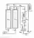
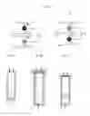


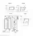
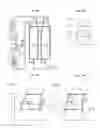
Sources:
- United States Patent and Trademark Office - verify current appl. status at the USPTO↗
Recent applications in this class:
- » 20230324082 2023-10-12
POSITIVE DISPLACEMENT MACHINE, COMPRESSOR, COOLING APPARATUS, AND ELECTRONIC EQUIPMENT - » 20220154979 2022-05-19
Engine system - » 20210356175 2021-11-18
Reciprocating-type compressor for refrigeration and/or conditioning and/or heat pump system - » 20210293457 2021-09-23
Aluminum compressor with sacrificial cladding - » 20210222915 2021-07-22
Linear compressor - » 20200333048 2020-10-22
Vapor compression refrigeration system - » 20200149783 2020-05-14
LINEAR MOTOR, COOLING EQUIPMENT COMPRESSOR, COOLING EQUIPMENT AND STATOR APPLICABLE IN A LINEAR MOTOR - » 20200003454 2020-01-02
Linear compressor - » 20190277540 2019-09-12
Cylinder head cover for a refrigerant compressor - » 20180356128 2018-12-13
Converting compressor to variable VI compressor
Recent applications for this Assignee:
- » 20250294920 2025-09-18
METHOD FOR FORMING A LAYER WITH THE BASIS OF A DIELECTRIC MATERIAL ON A LAYER WITH THE BASIS OF AN ETCHED III-V MATERIAL - » 20250288576 2025-09-18
SPECIFIC TETRADENTATE COPPER CHELATORS AS ANTICANCER AGENTS - » 20250288544 2025-09-18
PROBENECID FOR USE IN TREATING EPILEPTIC DISEASES, DISORDERS OR CONDITIONS - » 20250284027 2025-09-11
METHOD FOR CHARACTERIZING A GEOLOGICAL RESERVOIR OF INTEREST - » 20250279163 2025-09-04
METHODS, SYSTEMS, AND COMPUTER READABLE MEDIA FOR APTAMER SELECTION - » 20250277965 2025-09-04
MODULE INTENDED TO BE ASSOCIATED WITH A MICROSCOPE, AND ASSEMBLY FORMED BY A MICROSCOPE AND SUCH A MODULE - » 20250275994 2025-09-04
Quinoline Derivatives For Use In The Treatment Of Inflammation Diseases - » 20250263523 2025-08-21
NOVEL PLASTICIZERS, PROCESS FOR THE PREPARATION THEREOF, AND USE THEREOF - » 20250259818 2025-08-14
SYSTEM AND METHOD FOR SURFACE TREATMENT OF MATERIALS - » 20250250240 2025-08-07
PHENAZINE COMPOUND FOR MEASURING BACTERIAL EFFLUX