Ding inspection device
US20120073363A1
2012-03-29
12/888,500
2010-09-23
✅ Patent granted
US 8,151,658 B1
2012-04-10
-
-
John Fitzgerald
2030-09-23
Abstract:
Visual inspection of an interior bottom of a borehole by means of measuring the sediment thickness at the bottom. An inspection device to be lowered in the borehole and then to be retrieved. The bottom sediment thickness is marked on the piston by a collar attached to the piston.
Assignee:
- John Z. Ding 1 🇺🇸 Midlothian, VA, United States
Interested in similar patents?
Get notified when new applications in this technology area are published.
Classification:
E21B47/04 » CPC further
Survey of boreholes or wells Measuring depth or liquid level
E21B47/09 » CPC further
Survey of boreholes or wells Locating or determining the position of objects in boreholes or wells, e.g. the position of an extending arm ; Identifying the free or blocked portions of pipes
E21B47/00 » CPC main
Survey of boreholes or wells
Description
CROSS-REFERENCE TO RELATED APPLICATIONS
None
STATEMENT REGARDING FEDERALLY SPONSORED RESEARCH (IF APPLICABLE)
The invention was not made under a government contract, or federal fund.
BACKGROUND OF THE INVENTION
As a critical part of the drilled shaft quality control (FHWA, 1999), inspecting the bottom cleanliness of drilled shafts has always been challenging to contractors, engineers, and field inspectors, especially in the situation of the wet construction method, when direct visual inspections are impossible. Even with the dry construction method, inspectors have been reluctant to inspect the bottom visually due to safety concerns. On the other hand, most federal and local agencies, such as states' department of transportation and city building authorities specify that drilled shafts be inspected for bottom cleanliness. Typically, a minimum of 50 percent of the base of each shaft should have less than 0.5 inch of sediment at the time of concrete placement, and the maximum depth of sediment or any debris at any place on the base of the shaft is not allowed to exceed 1.5 inches. Conscientious cleaning of the bottom of drilled shafts has been proven by loads tests to be necessary for suitable load transfer in end bearing.
Currently, the Shaft Inspection Device (SID) or Miniature Shaft Inspection Device (Min-SID) are the only devices recognized as being relatively accurate to measure the drilled shaft bottom sediment without an inspector's direct measurement in the hole.
SID was developed in the early 1980s by Schmertmann and Crapps, Inc. The SID comprises a television camera sealed inside a water-tight jacket and is used for inspecting both dry and wet excavations. The concept of the SID was derived from an Australian drilled shaft inspection device originally developed by Dr. Jim Holden of the Country Roads Board. SID is a heavy (over 1000 lb) and large equipment. The operation is relatively expensive and time consuming.
Mini-SID was introduced around 1998 with much lighter weight and easier operation procedures. However, it still involved the operations of specifically trained personnel and relatively time consuming test procedures.
Given these reasons, a portable drilled shaft inspection device with improved efficiency is desired. The device should have the following key points:
-
- 1. Simple Operating Process
- 2. Very Efficient
- 3. High Reliability
SUMMARY OF THE INVENTION
Embodiments of the invention include a mechanical device of approximately 20 pounds (9 kg). The dimensions of the device are approximately 7.5 inches (188 mm) in diameter, and 9 inches (225 mm) high. The device provide following benefits for the drilled shaft inspection:
-
- 1. No need of the human excess into the boring hole
- 2. Acceptable accuracy of the measurement of the drilled shaft bottom sediments.
- 3. A pure mechanical device operated as a hand tool.
- 4. Easy operating procedures without the need of specially training personnel to use the device.
- 5. Dramatically improved efficiency.
DESCRIPTION OF THE DRAWING
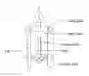
FIG. 1 is the schematic sketch of the device
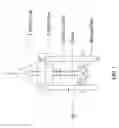
FIG. 2 is a picture overview of the device.
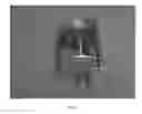
FIG. 3 is a picture side view of the device showing the details of the collar and the imprinted marks on the piston.
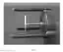
FIG. 4 is the picture for the replaceable bottom plate.
FIG. 5 is the design details A.
FIG. 6 is the design details B
FIG. 7 is the design details C
DETAILED DESCRIPTION OF INVENTION
Referring to the drawings, FIG. 1 illustrates the schematic sketch of the Ding Inspection Device (DID). As shown, the system includes a steel upper plate, three steel legs attached to the upper plate, a steel piston with imprinted marks of 0.25 inches increments, an aluminum sliding collar with a rubber O-ring embedded inside the collar, an aluminum bottom plate with 16 0.5″-diameter holes, three lifting holes attached to the upper plate.
The inspection procedure includes six essential steps:
-
- 1. Set the device on a level flat solid area so that the bottom of the plate is level with the tips of the three legs.
- 2. Set the “zero” reading by pushing the collar on the piston until it touches the bottom of the upper plate. The “zero” reading is at the bottom of the collar.
- 3. Slowly lower the device into the drilled shaft. If there is liquid in the shaft, careful attention should be paid to the moment when the bottom plate comes in contact with the liquid so that the impact pressure of the liquid does not move the plate up. As a reference, the drop speed of the device should be less than 0.1 inch/second at the moment when the plate contacts the liquid surface and the maximum speed for the device in the liquid should be less than 3.5 inch/second (Approximately 3 minutes for a slurry shaft of 50 feet deep).
- 4. After the device is set at the drilled shaft bottom, retrieve the device.
- 5. Take reading at the bottom of the collar.
- 6. Repeat steps 1 to 5 if additional readings are required.
FIG. 2 is a photographic overview of the device.
FIG. 3 is a photographic side view of the device showing the details of the collar and the imprinted marks on the piston.
FIG. 4 is the photographic view for the replaceable aluminum bottom plate.
FIG. 5 is the design details A. The drawing shows all the dimension details and the connection method.
FIG. 6 is the cross section view marked in FIG. 5.
FIG. 7 is the design details for the bottom plate and the sliding collar.
Claims
1. An inspection device comprising an upper steel plate, three steel legs attached to the upper plate, a steel piston with imprinted marks a sliding collar, a bottom plate with holes, three lifting holes attached to the upper plate for insertion into a borehole for measuring sediment thickness at the bottom of the hole.
2. A method of inspecting a borehole, either dry or into a slurry, by means of measuring the sediment thickness at the borehole bottom using said device of claim 1.
3. The inspection device of according to claim 1 where-in the upper plate comprises a 6″ diameter and 2″ thick steel plate.
4. The inspection device of according to claim 1 where-in the piston comprises a 0.5″ diameter steel bar with a 0.75 diameter cap on top of the bar as a stopper of the piston and bottom plate.
5. (canceled)
6. The inspection device of according to claim 1 where-in the three legs comprises steel bars with 60 degree sharpened tips.
7. The inspection device of according to claim 1 where-in the lower plate comprises a 5″ diameter and 0.25″ thick aluminum plate with 16 holes of 0.5″ diameter.
8. The inspection device according to claim 1 where-in the collar comprises a 0.5″ long aluminum tube with a rubber 0.5″ diameter O-ring embedded into a notch inside the tube.
Images & Drawings included:


Sources:
- United States Patent and Trademark Office - verify current appl. status at the USPTO↗
Similar patent applications:
- » 20150211353
Digital Ding Inspection Device
Recent applications in this class:
- » 20250290402 2025-09-18
DOWNHOLE GYROSCOPIC SURVEYING MEASUREMENTS UNDER DYNAMIC CONDITIONS - » 20250283401 2025-09-11
SYSTEM TO MODEL DISTRIBUTED TORQUE, DRAG AND FRICTION ALONG A STRING - » 20250179905 2025-06-05
SYSTEMS AND METHODS OF PREDICTIVE DECLINE MODELING BASED ON TIME-DEPENDENT DEPLETION FUNCTION - » 20250092775 2025-03-20
Engineered Acoustics For Downhole Equipment - » 20250075611 2025-03-06
SYSTEMS AND METHODS FOR AUDITABLE EMISSION MODELS - » 20250012182 2025-01-09
SYSTEM AND METHOD FOR DEPLOYING SENSING CABLE INTO A WELL - » 20240247581 2024-07-25
SYSTEM AND METHOD FOR TRACKING A STATE OF DISSOLVABLE DOWNHOLE TOOLS - » 20240060413 2024-02-22
Orchestration framework to determine composite well construction recommendations - » 20230228183 2023-07-20
Real-time monitoring of swellpackers - » 20230193743 2023-06-22
Method and system for managing carbon dioxide supplies using machine learning