Adjustable Bra System
US20120077415A1
2012-03-29
13/244,475
2011-09-25
Abstract:
An adjustable bra system uses pockets 13 on the back side of balcony cups 12 to store demi cup material 11 to convert a demi cup bra to a balcony cup bra. Various bridges connect bra cups together; the bridges include a quick release clasp system 719 allowing the bra cups to quickly spring off the user. Other bridges include the use of offset or staggered 617 receiving snaps allowing for shape adjustment in the bridge area. Bra cups may also have multiple wire channels to accept adjustable wire. The bra cups may also have multiple openings to accept adjustable wire of various lengths.
Interested in similar patents?
Get notified when new applications in this technology area are published.
Classification:
A41C3/02 » CPC main
Brassieres with front closures
A41C3/0028 » CPC further
Brassieres with size and configuration adjustment means
A41C3/0071 » CPC further
Brassieres with interchangeable or detachable cups
A41C3/10 IPC
Brassieres with stiffening or bust-forming inserts
Description
CROSS-REFERENCE TO RELATED APPLICATIONS
This utility application is based upon U.S. patent application Ser. No. 61386309 filed on or about Sep. 24, 2010. This related application is incorporated herein by reference and made part of this application. If any conflict arises between the disclosure of the invention in this utility application and that in the related provisional application, the disclosure in this utility application shall govern. Moreover, the inventor incorporates herein by reference any and all patents, patent applications, and other documents hard copy or electronic, cited or referred to in this application.
COPYRIGHT AND TRADEMARK NOTICE
This application includes material which is subject or may be subject to copyright and/or trademark protection. The copyright and trademark owner(s) has no objection to the facsimile reproduction by any of the patent disclosure, as it appears in the Patent and Trademark Office files or records, but otherwise reserves all copyright and trademark rights whatsoever.
BACKGROUND OF THE INVENTION
(1) Field of the Invention
The invention generally relates to bra systems. More particularly, the invention relates to devices, means and methods of creating adjustable bra systems with different support wire channel structures, adjustable cup structures, adjustable bridge structures, adjustable wire length structures and quick release clasp structures.
(2) Description of the Related Art
In the related art, bras are sold in fixed configurations such that a purchaser may obtain a balcony cup bra, demi cup bra or other single function or single style bra. In the related art, bra support structures, such as wires are rigidly attached to the bra and do not allow for multiple cup configurations.
U.S. Pat. No. 5,496,205 issued on Mar. 5, 1996 to Lee discloses a brassier having concealed pockets, but fails to disclose or anticipate means or methods of converting a demi cup bra to a balcony cup bra by use of cup enclosures and folding bra material.
U.S. Pat. No. 7,585,200 issued on Sep. 8, 2009 to McLaren discloses a detachable holder that is attached to a bra, but fails to provide a convertible bra style.
U.S. patent
BRIEF SUMMARY OF THE INVENTION
The present invention overcomes shortfalls in the related art by presenting an unobvious and unique combination and configuration of bra material, bra support material, pockets, multiple channels for bra wires, bra bridge systems, quick release systems and other features. The disclosed bra systems allow a purchaser various bra style options, such as balcony cup, demi cup, and others and allows a purchaser to use multiple wire channels to adapt to user needs and selected bra styles. A quick release clasp doubles as a bridge and allows a bra to snap off at the center bridge.
One of the main advantages of this invention is the use of common wire channels with adjoining forked channels. The use of a forked channel allows for a relatively small section of wire to be moved from one fork to another to accommodate the selected bra style. The longer common wire and common wire channel remain undistributed.
Another advantage of the invention is the use of pockets within the bra material to hold unused bra sections. For example, when converting from a demi cup to a balcony cup, an upper section of the demi cup may fold into a pocket, converting the bra to a balcony cup.
These and other objects and advantages will be made apparent when considering the following detailed specification when taken in conjunction with the drawings.
BRIEF DESCRIPTION OF THE DRAWINGS
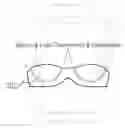
FIG. 1 presents a balcony cup bra
FIG. 2 presents a balcony cup bra with balcony cup underwire
FIG. 3 presents balcony cup channeling and underwire
FIG. 4 presents balcony cup underwire and demi cup underwire
FIG. 5 presents balcony cup underwire and demi cup underwire
FIG. 6 presents an enlarged view of both balcony cup and demi cup underwire
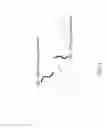
FIG. 7 presents a side view of a underwire casing and slider system
FIG. 8 presents a double configuration and side view of underwire casing and an underwire slider
FIG. 9 presents an underwire casing, underwire slider and a slider inserted into a casing.
FIG. 10 presents various views of underwire
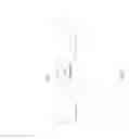
FIG. 11 presents a balcony bra with slit openings for insertion of adjustable length underwire
FIG. 12 presents a balcony bra with adjustable length underwire
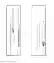
FIG. 13 presents a front view of an adjustable bridge
FIG. 14 presents an expanded view of an adjustable bridge
FIG. 15 presents a front view of an adjustable bridge in a first configuration
FIG. 16 presents a front view of an adjustable bridge in a second configuration
FIG. 17 presents an expanded view of an adjustable bridge in a first configuration
FIG. 18 presents a front view of a bridge in a third configuration
FIG. 19 presents an inside view of a bridge in a third configuration
FIG. 20 is an expanded front view of a bridge in a third configuration
FIG. 21 is an expanded inside view of a bridge in a third configuration
FIG. 22 is an inside view of a bridge in a third configuration
FIG. 23 is a front view of a slider bridge or a bridge in a front configuration
FIG. 24 is a back view of a bridge in a slider configuration
FIG. 25 is a front view of a bow tie bridge or a bridge in a bow tie configuration
FIG. 26 is a back view of a bridge in a bow tie configuration
FIG. 27 is a front view of a first snap bridge or a bridge in a first snap configuration
FIG. 28 is a back view of a first snap bridge or a bridge in a first snap configuration
FIG. 29 is an exploded view from FIG. 28 showing snaps
FIG. 30 is a front view of a second configuration of a snap bridge
FIG. 31 is a back view of a second configuration of a snap bridge
FIG. 32 is an exploded view of snaps from FIG. 31
FIG. 33 is a front view of a first configuration of a hook and eye bridge
FIG. 34 is a back view of a first configuration of a hook and eye bridge
FIG. 35 is an exploded view of loops from a first configuration of a hook and eye bridge
FIG. 36 is a front view of a second configuration of a hook and eye bridge
FIG. 37 is a back view of a second configuration of a hook and eye bridge
FIG. 38 is an exploded view of loops from a second configuration of a hook and eye bridge
FIG. 39 is a front view of a demi cup configuration ready to convert into a balcony cup configuration.
FIG. 40 is a plan view of the front side of a square clasp
FIG. 41 is a plan view of the back side of a square clasp
FIG. 42 is a plan view of the front side of a round clasp
FIG. 43 is a plan view of the back side of a round clasp
FIG. 44 is a plan view of the front side of a shield shaped clasp
FIG. 45 is a plan view of the back side of a shield shaped clasp
FIG. 46 presents various perspective views of clasp components
FIG. 47 presents four views of a clasp used as a bridge
FIG. 48 is a back view of a demi cup being converted to a balcony cup by use of a cup pocket
REFERENCE NUMERALS IN THE DRAWINGS
10 a demi cup bra configuration
11 demi cup material
12 balcony cup
13 pocket within balcony cup, sometimes used to store demi cup material 11
14 seams defining the pocket 13 within the balcony cup
200 a balcony cup bra
201 balcony cup underwire
202 balcony cup channeling and underwire
301 demi cup underwire
400 adjustable length underwire
401 underwire casing
402 underwire slider in a single configuration
403 underwire slider in a double configuration
404 underwire casing as shown in a bottom view
405 underwire slider shown in a top view
406 a slider inserted into an underwire casing, top view
407 a perspective view of a underwire casing or housing
408 a perspective view of underwire
409 a slider inserted into a casing in a single configuration
410 a notch on a slider
411 notch receiving areas with an underwire casing 401
500 slit or void openings for insertion of adjustable length underwire
600 a contemplated bridge in a first configuration
601 slit for bridge to slide through
602 rectangular grommet or ring
603 a general channel for a bra cup
604 a bridge in a second configuration
605 a bridge in a third configuration as seen from the front
606 a bridge in a third configuration as seen from the inside
607 a bridge in a slider configuration also known as a slider bridge
608 a rectangular loop or ring of a slider bridge
609 a bow tie bridge or a bridge in a bow tie configuration
610 a bow tie slit
611 a bow tie hook
612 a bow tie loop
613 is a first embodiment of a snap or snaps bridge or a bridge in a first snap bridge configuration
614 snaps of a first embodiment or first configuration of a snap bridge
615 is a second embodiment of a snap or snaps bridge or a bridge in a second snap configuration
616 snaps of a second embodiment of a snap bridge
617 staggered or offset receiving snaps of a second embodiment of a snap bridge
618 is a first embodiment of a hook and eye bridge
619 are loops or eyes on the inside of a first embodiment of a hook and eye bridge
620 are hooks for insertion into the loops or eyes 619 of a hook and eye bridge 618
621 is a second embodiment of a hook and eye bridge
622 are loops or eyes on the inside of a second embodiment of a hook and eye bridge
623 offset or staggered receiving hooks used to secure loops 622.
624 grommet securing material, bridging the gap between channeling material or a bra cup and a grommet.
700 front side of a square clasp piece
701 back side of a square clasp piece
702 front side of a round clasp piece
703 back side of a round clasp piece
704 is a front side of a shield shape clasp piece
705 is a back side of a shield shape clasp piece
710 a spring for the spring casing 711
711 spring casing or spring housing to retain the spring 710
712 spring inside of spring housing
713 spring slider
714 spring slider attached to spring and spring casing, internal view
715 spring slider attached to spring and spring casing, external view
716 grommet defined by upper wall of spring slider 713
717 slider
718 grommet defined by upper wall of slider 717
719 complete quick release clasp
720 bra bridge material, sometimes used to secure bra cups to bridge components
DETAILED DESCRIPTION OF EMBODIMENTS OF THE INVENTION
The following detailed description is directed to certain specific embodiments of the invention. However, the invention can be embodied in a multitude of different ways as defined and covered by the claims and their equivalents. In this description, reference is made to the drawings wherein like parts are designated with like numerals throughout.
Unless otherwise noted in this specification or in the claims, all of the terms used in the specification and the claims will have the meanings normally ascribed to these terms by workers in the art.
Unless the context clearly requires otherwise, throughout the description and the claims, the words “comprise,” “comprising” and the like are to be construed in an inclusive sense as opposed to an exclusive or exhaustive sense; that is to say, in a sense of “including, but not limited to.” Words using the singular or plural number also include the plural or singular number, respectively. Additionally, the words “herein,” “above,” “below,” and words of similar import, when used in this application, shall refer to this application as a whole and not to any particular portions of this application.
The above detailed description of embodiments of the invention is not intended to be exhaustive or to limit the invention to the precise form disclosed above. While specific embodiments of, and examples for, the invention are described above for illustrative purposes, various equivalent modifications are possible within the scope of the invention, as those skilled in the relevant art will recognize. For example, while steps are presented in a given order, alternative embodiments may perform routines having steps in a different order. The teachings of the invention provided herein can be applied to other systems, not only the systems described herein. The various embodiments described herein can be combined to provide further embodiments. These and other changes can be made to the invention in light of the detailed description.
Any and all the above references and U.S. patents and applications are incorporated herein by reference. Aspects of the invention can be modified, if necessary, to employ the systems, functions and concepts of the various patents and applications described above to provide yet further embodiments of the invention.
These and other changes can be made to the invention in light of the above detailed description. In general, the terms used in the following claims, should not be construed to limit the invention to the specific embodiments disclosed in the specification, unless the above detailed description explicitly defines such terms. Accordingly, the actual scope of the invention encompasses the disclosed embodiments and all equivalent ways of practicing or implementing the invention under the claims.
Referring to FIG. 1, a balcony cup bra 200 is shown upon a drawn model. FIG. 2 shows a balcony cup underwire 201. FIG. 3 shows balcony cup channeling and underwire 202. A channel is a sleeve or other type of void sometimes used to secure underwire. Underwire is sometimes used to add support to a bra cup.
FIG. 4 shows a contrast between a balcony cup underwire 201 and a demi cup underwire 301. The difference between the two become most apparent at the cleavage area or area were the two bra cups connect. One aspect of one embodiment of a disclosed bra system is that a bra may have multiple wire channels to accommodate different wire configurations. FIG. 4 features a multi-channel underwire bra that enables a wearer to switch between various bra cup shapes. FIG. 5 presents an alternative view of FIG. 4
FIG. 6 presents an expanded view of FIG. 5, highlighting the different shapes of a balcony cup underwire 201 and a demi cup underwire 301.
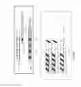
FIG. 7 a side view of a single configuration of components comprising an underwire casing 401, an underwire slider 402 and a slider inserted into a casing 409.
FIG. 8 presents a side view of a double configuration of a casing and underwire slider 403
FIG. 9 presents a top view of underwire casing 404 with notch receiving areas 411 that sometimes receive notches 410 from sliders. A top view of a slider 405 is shown with one notch 410. FIG. 9 also shows 406 an underwire slider inserted into a casing.
FIG. 10 shows two views of an underwire casing or housing 407 and one view of an underwire 408. Both notches 410 and notch receiving areas 411 are shown.
FIG. 11 presents a plan view of bra having voids 500 defined by the underwire channeling, the voids sometimes used to accept adjustable length underwire.
FIG. 12 shows adjustable length underwire 400 as inserted into a channel.
FIG. 13 presents a first configuration of an adjustable bridge 600. A front view of a bra and bridge 600 is shown.
FIG. 14 presents an expanded view of bridge 600, and more carefully showing a void or slit 601 used for accepting the bridge 600. The slit 601 is defined by the interior surfaces of the grommet 602 or ring, which sometimes takes the shape of a rectangle. Channeling material 603 is shown to the outside either grommet 602. Grommet securing material 623 is shown in connection with channeling 603 and grommet or ring 602.
FIG. 15 presents a front view of a first bridge configuration 600. FIG. 16 presents a front view of a second bridge configuration 604. In the second configuration, the grommet is parallel to the channel.
FIG. 17 presents another front view of an adjustable bridge, capable of adjustment from a first configuration 600 to a second configuration 604.
FIG. 18 presents a front view of a third bridge configuration 605 wherein the grommet is built into the bra cup or channel material.
FIG. 19 presents an inside view of a bar showing the inside portions 606 of a third bridge configuration.
FIG. 20 is an expanded front view of the third presented bridge configuration 605. The grommet is built into a void within the channel. The grommet defines a void to accept the bridge material.
FIG. 21 is an expanded inside view 606 of the third presented bridge. Here again, the grommet and void are contained within the underwire channeling.
FIG. 22 presents an alternative inside view of the third presented bridge 606, integrated with underwire channeling.
FIG. 23 is a front view of a slider bridge 607, the slider bridge material, sometimes shown as 607, passes through a loop 608 and then one or more sliders 609 for adjustment. The sliders 609 sometimes take the form of two connected loops.
FIG. 24 is a back view of a slider bridge and presents cut-a-way views of bridge material fitted into a loop 608 and one or more sliders 609.
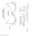
FIG. 25 is a front view of a bow tie bridge 609.
FIG. 26 is a back view of a bow tie bridge having voids or slits 610 defined by the bridge material, and having a hook 611 and a bow tie loop 612. The bridge material may be placed in or around the bow tie loop 612 and the bow tie loop may be connected to the bow tie hook 611 for insertion into the voids 610.
FIG. 27 is a front view of a first configuration of a snap or snaps bridge 613. FIG. 28 is a back view of a first configuration of a snap or snaps bridge showing snaps 614. FIG. 29 presents an exploded view of snaps 614.
FIG. 30 is a front view of second snap bridge configuration 615. FIG. 31 shows an offset or staggered set or receiving snaps 617. The offset snaps 617 provide additional adjustment to the bridge angle. FIG. 32 provides an exploded view of snaps 616.
FIG. 33 provides a front view of a hook and eye bridge 618. FIG. 34 is a back side view showing loops 619 or eyes and hooks 620. FIG. 35 is an exploded view of the eyes or hooks 619.
FIG. 36 is a front view of a second embodiment 621 of a hook and eye configuration. FIG. 37 is a back view of the second hook and eye embodiment and shows loops 622 and offset receiving hooks 623. FIG. 38 is an expanded view of loops 622.
FIG. 39 is a front view of a demi cup configuration 10 having a hidden pocket 13 inside connected balcony cup, allowing the demi cup material 11 to fold into the hidden pocket 13.
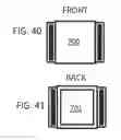
FIG. 40 is a plan view of the front side of a square clasp 700. FIG. 41 shows the back side 701 of a square clasp.
FIG. 42 is a plan view of the front side 702 of a round clasp. FIG. 43 is the back side 703 of a round clasp.
FIG. 44 is front view 704 of a shield shaped clasp. FIG. 45 is a back view 705 of a shield shaped clasp.
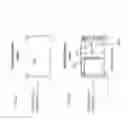
FIG. 46 presents a quick release clasp system 719, comprising a spring 710, spring case or spring housing 711, a spring inside of the casing 712, a spring slider 713, with the spring slider having a connection point 716 to accept bra bridge material. The spring and spring casing may fit into the spring slider as shown at 714. The spring slider with spring and spring casing assembly 715 may be an independent piece that fits in and out of a larger slider 717. The slider 717 will have a bra material attachment point 718.
FIG. 47 presents four views of a bra system with a quick release clasp system 719 used as a bridge between two bra cups. Bra material 720 can be seen attached to clasp connection points 716 and 718. The quick release system 719 can be seen in a state of separation with the spring slider 713 separated from the slider 717.
FIG. 48 is a back view of a demi cup bra being converted into a balcony bra. The demi cup material 11 can be seen going into the pocket 13, with the pocket being defined by pocket seam lines 14.
Embodiments of the disclosed systems include, but are not limited to the following items. Terms used in the items may be helpful in defining terms in the claims, but are not limiting.
Item 1. An adjustable bra system comprising:
- a) two balcony cups 12 attached to two sets of demi cup material 11;
- b) the bottom portions of the two balcony cups having channeling and underwire 202
- c) the two balcony cups having back sides with pockets 13 defined by seams 14 with the pockets 13 capable of holding the demi cup material, converting the bra system from a demi cup to a balcony cup;
- d) the two balcony cups connected with a quick release clasp 719 system, the quick release clasp system comprising:
- i) a first clasp component 715 comprising a spring 710, a spring casing 711, and a spring slider with the spring slider having a connection point 716 for attaching bra bridge material 720 connected to a bra cup;
- ii) with the first clasp component 715 fitting into a second component comprising a slider 717, with the slider having a connection point 718 for attaching bra bridge material 720 connected to a bra cup; and
- e) the two balcony cups each having two channel sections to two sets of underwire comprising balcony cup underwire 201 and demi cup underwire 301.
The adjustable bra system of item 1 using adjustable slider wire 402 with the slider wire having notches and the adjustable bra system using casing 401 with notch receiving areas 411 fitted to accept the notches on the slider wire.
The adjustable bra system of item 1 having a plurality of openings 500 defined by the underwire channeling fitted to adjustable length underwire 400.
The adjustable bra system of item 1 using a slider bridge to connect the two balcony cups, the slider bridge comprising a loop 608 connected to bra bridge material connected to a balcony cup, two or more sliders 609 with the sliders comprising two connected loops, with the sliders accepting material adjusted by the sliders to control the distance between the balcony cups.
Claims
What is claimed is:1. An adjustable bra system comprising:
a) two balcony cups attached to two sets of demi cup material;
b) the bottom portions of the two balcony cups having channeling and underwire;
c) the two balcony cups having back sides with pockets defined by seams with the pockets capable of holding the demi cup material, converting the bra system from a demi cup to a balcony cup;
d) the two balcony cups connected with a quick release clasp system, the quick release clasp system comprising:
i) a first clasp component comprising a spring, a spring casing, and a spring slider with the spring slider having a connection point for attaching bra bridge material connected to a bra cup;
ii) with the first clasp component fitting into a second component comprising a slider, with the slider having a connection point for attaching bra bridge material connected to a bra cup; and
e) the two balcony cups each having two channel sections to two sets of underwire comprising balcony cup underwire and demi cup underwire.
2. The adjustable bra system of claim 1 using adjustable slider wire, with the slider wire having notches and the adjustable bra system using casing with notch receiving areas fitted to accept the notches on the slider wire.
3. The adjustable bra system of claim 1 having a plurality of openings defined by the underwire channeling fitted to adjustable length underwire.
4. The adjustable bra system of claim 1 using a slider bridge to connect the two balcony cups, the slider bridge comprising a loop connected to bra bridge material connected to a balcony cup, two or more sliders with the sliders comprising two connected loops, with the sliders accepting material adjusted by the sliders to control the distance between the balcony cups.
Images & Drawings included:


Sources:
- United States Patent and Trademark Office - verify current appl. status at the USPTO↗
Similar patent applications:
- » 20060252346
Athletic bra with adjustable support system - » 20120034841
System for adjusting the fit of a bra to a wearer's bosom
Recent applications in this class:
- » 20250160447 2025-05-22
Clasp - » 20240180267 2024-06-06
Systems and methods for a bra for use with limited mobility - » 20240108083 2024-04-04
CLOSURE SYSTEM FOR GARMENTS - » 20230389624 2023-12-07
SYSTEMS AND METHODS FOR A BRA FOR USE WITH LIMITED DEXTERITY - » 20230255275 2023-08-17
ADJUSTABLE MULTI-LAYER BRA - » 20230240383 2023-08-03
Systems and methods for a bra for use with limited mobility - » 20230049200 2023-02-16
BRA SUPPORT HARNESS FOR ADJUSTING SUPPORT AND COMPRESSION - » 20220378117 2022-12-01
Adaptive Wrap Top - » 20210084995 2021-03-25
Adjustable multi-layer bra - » 20140364037 2014-12-11
REVERSIBLE BRA