Ultraviolet angled spray nozzle
US20120082790A1
2012-04-05
12/894,226
2010-09-30
✅ Patent granted
US 9,550,198 B2
2017-01-24
-
-
Yewebdar Tadesse
Carlson, Gaskey & Olds, PC
2031-03-10
Abstract:
An apparatus for masking an article with masking material is disclosed. The apparatus generally includes a spray head connected to a primary channel which forms a passage for the masking material. This channel has two sections, the first of which terminates in a junction with the spray head and is angled from the second section. In addition, the apparatus has at least one secondary channel which forms an air passage and is attached to the primary angled channel
Inventors:
- George H. Reynolds 17 🇺🇸 Sanford, ME, United States
- James J. Foster 2 🇺🇸 Wells, ME, United States
Assignee:
- UNITED TECHNOLOGIES CORPORATION 4,046 🇺🇸 Hartford, CT, United States
Applicant:
Interested in similar patents?
Get notified when new applications in this technology area are published.
Classification:
B05B7/062 » CPC main
Spraying apparatus for discharge of liquids or other fluent materials from two or more sources, e.g. of liquid and air, of powder and gas; Spray pistols; Apparatus for discharge with at least one outlet orifice surrounding another approximately in the same plane with only one liquid outlet and at least one gas outlet
F23R3/14 » CPC further
Continuous combustion chambers using liquid or gaseous fuel characterised by the air-flow or gas-flow configuration; Air inlet arrangements for primary air inducing a vortex by using swirl vanes
C23C4/01 » CPC further
Coating by spraying the coating material in the molten state, e.g. by flame, plasma or electric discharge Selective coating, e.g. pattern coating, without pre-treatment of the material to be coated
C23C10/04 » CPC further
Solid state diffusion of only metal elements or silicon into metallic material surfaces Diffusion into selected surface areas, e.g. using masks
C23C24/00 » CPC further
Coating starting from inorganic powder
C23C14/042 » CPC further
Coating by vacuum evaporation, by sputtering or by ion implantation of the coating forming material; Coating on selected surface areas, e.g. using masks using masks
B05D1/32 IPC
Processes for applying liquids or other fluent materials using means for protecting parts of a surface not to be coated, e.g. using stencils, resists
B05B13/0431 » CPC further
Machines or plants for applying liquids or other fluent materials to surfaces of objects or other work by spraying, not covered by groups - ; Means for supporting work; Arrangement or mounting of spray heads; Adaptation or arrangement of means for feeding work the spray heads being moved during spraying operation with spray heads moved by robots or articulated arms, e.g. for applying liquid or other fluent material to 3D-surfaces
F01D5/286 » CPC further
Blades; Blade-carrying members ; Heating, heat-insulating, cooling or antivibration means on the blades or the members; Blades; Selecting particular materials; Particular measures relating thereto; Measures against erosion or corrosion Particular treatment of blades, e.g. to increase durability or resistance against corrosion or erosion
F23C7/004 » CPC further
Combustion apparatus characterised by arrangements for air supply the air being submitted to a rotary or spinning motion using vanes
C23C8/04 » CPC further
Solid state diffusion of only non-metal elements into metallic material surfaces ; Chemical surface treatment of metallic material by reaction of the surface with a reactive gas, leaving reaction products of surface material in the coating, e.g. conversion coatings, passivation of metals Treatment of selected surface areas, e.g. using masks
B05D1/322 » CPC further
Processes for applying liquids or other fluent materials using means for protecting parts of a surface not to be coated, e.g. using stencils, resists Removable films used as masks
F05D2230/90 » CPC further
Manufacture Coating; Surface treatment
F23R2900/00018 » CPC further
Special features of, or arrangements for continuous combustion chambers; Combustion processes therefor Manufacturing combustion chamber liners or subparts
B05B13/04 » CPC further
Machines or plants for applying liquids or other fluent materials to surfaces of objects or other work by spraying, not covered by groups - ; Means for supporting work; Arrangement or mounting of spray heads; Adaptation or arrangement of means for feeding work the spray heads being moved during spraying operation
B05B7/06 IPC
Spraying apparatus for discharge of liquids or other fluent materials from two or more sources, e.g. of liquid and air, of powder and gas; Spray pistols; Apparatus for discharge with at least one outlet orifice surrounding another approximately in the same plane
B05B3/00 IPC
Spraying or sprinkling apparatus with moving outlet elements or moving deflecting elements ; Spraying or sprinkling heads with rotating elements located upstream the outlet
B05B1/28 IPC
Nozzles, spray heads or other outlets, with or without auxiliary devices such as valves, heating means with integral means for shielding the discharged liquid or other fluent material, e.g. to limit area of spray; with integral means for catching drips or collecting surplus liquid or other fluent material
F01D5/28 IPC
Blades; Blade-carrying members ; Heating, heat-insulating, cooling or antivibration means on the blades or the members; Blades Selecting particular materials; Particular measures relating thereto; Measures against erosion or corrosion
F23C7/00 IPC
Combustion apparatus characterised by arrangements for air supply
C23C14/04 IPC
Coating by vacuum evaporation, by sputtering or by ion implantation of the coating forming material Coating on selected surface areas, e.g. using masks
Description
BACKGROUND
This disclosure generally relates to an apparatus, a system, and a method for masking articles, and more particularly, to an apparatus, a system, and a method for masking articles of complex geometry not conducive to traditional spray masking.
Generally, it is known to mask and coat articles in order to protect them from degradation and wear during operation. Existing apparatuses dedicated to this task are limited by the geometry of the parts which they attempt to mask, since they typically have a sprayer connected directly and immovably to a large, blunt spraying mechanism. For this reason, it is difficult to mask parts with complex geometries prior to the coating process.
Specifically, high pressure compressor vanes are known to be exposed to extreme temperatures and pressures during the course of their operation. In order to reduce the amount of degradation and wear, the parts are typically coated with a protective material. The process of applying such a coating involves rapidly heating the material and accelerating the material at the part. This process can be damaging to the part and thus, masking with an ultraviolet (UV) curable material prior to coating is common practice.
During the masking process, a masking material is sprayed out of a central channel and air is sprayed out of at least one secondary channel. Combining the jet of air with the jet of masking material causes the atomization of the masking material, which improves the adhesion of the masking material to the substrate.
After the article has been masked, the coating material is heated and accelerated toward the partially-masked substrate. The masked surface is protected from the harsh effects of the coating process.
SUMMARY
An apparatus for masking an article with masking material is disclosed. The apparatus generally includes a spray head connected to a primary channel which forms a passage for the masking material. This channel has two portions: a first portion terminates in a junction with the spray head, and a second portion other terminates with a rotatable connection to an existing spraying machine. The first portion is angled from the second portion. In addition, the apparatus has at least one secondary channel which forms an air passage. The air passage is attached to the primary angled channel and at least one point along the length of the primary angled channel.
These and other features of the present disclosure can be best understood from the following specification and drawings, the following of which is a brief description.
BRIEF DESCRIPTION OF THE DRAWINGS
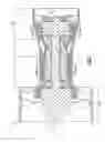
FIG. 1 is a sectional view of an axial flow, turbo fan gas turbine engine.
FIG. 2A is a perspective view of the airfoils in application to the vanes of a gas turbine engine.
FIG. 2B is a perspective view of the interaction between a prior art sprayer and a traditional compressor vane assembly.
FIG. 2C is a side view of the interaction between an embodiment of the disclosure and a traditional compressor vane assembly.
FIG. 2D is a side view of the interaction between the embodiment in FIG. 2C and a traditional compressor vane assembly in an alternate position.
FIG. 3A is a side view of an embodiment of the apparatus.
FIG. 3B is a section view of the nozzle and air channels taken from section A.
FIG. 4 is a pictorial illustration of the coating process following masking.
FIG. 5 is a method chart outlining the masking and coating processes.
DETAILED DESCRIPTION
FIG. 1 illustrates a sectional view of an axial flow, turbo fan gas turbine engine 10 which comprises of a compressor section 14, a combustion section 16, a turbine section 18, and a fan 30. The turbine has rotating blades 22 which are fixed to rotors 28 which rotate about the centerline 12. In addition the turbine 18 has vanes 20, which remain fixed with respect to the blades 22. Similarly, the compressor 14 has vanes 26, and rotating blades 24 connected to a rotor 28 which rotates about the centerline 12.
FIG. 2A shows a perspective view of vanes 26. As shown, the vanes 26 are curved and nested within each other. Given such a closely-spaced orientation, it is difficult to apply a mask to the surfaces.
FIG. 2B shows the limitations of the prior art apparatus 32 for coating airfoils 62 such as the vanes 26 of a compressor 14. The prior art apparatus 32 can only partially mask section 34 of two airfoils 62 of relatively complex geometry in series. The remainder of the airfoils 62 remain unmasked, as seen by sections 54 and 56, since the prior art apparatus 32 cannot reach around the curved surfaces due to its existing geometry.
FIG. 2C shows the spray apparatus 36 of the disclosure which can fully mask 34 the complex geometry of the airfoils 62 in series. In contrast to FIG. 2A, the entire surface of the airfoils 62 is masked due to the spray apparatus's ability to rotate and translate about the axis 64. The spray apparatus may be configured to rotate and translate simultaneously, though the steps of rotating and translating the spray apparatus may be performed separately or in series.
FIG. 2D shows the spray apparatus 36 of the disclosure as in FIG. 2C in a secondary orientation. In this second orientation, the apparatus 36 has been rotated and translated about the vertical axis 64.
FIG. 3A shows a side view of the spray apparatus 36 described in this disclosure. The apparatus 36 is rotatably attached to an existing spraying machine 70 and connected to the supply of masking material 72 and an air tank 74 by adapter 38. The supply of masking material 72 and the air tank 74 may be associated with an actuator capable of propelling masking material 72 through the channel 40, for example, while concurrently passing air through air channels 60. Alternatively, the supply of masking material 72 and the air tank 74 may be provided with separate, individual actuators capable of such concurrent operation.
The adapter 38 is connected to a longer second portion 42 of the apparatus, which is of length d1. The second portion 42 is connected to a first portion 44, which is of length d2, and is at an angle 50 from the centerline of the apparatus 48. In this embodiment, the angle 50 is approximately 45° and the ratio of d1 to d2 is substantially equal to 2:1. In other embodiments, the angle 50 can be between 35° and 145°, and the ratio of d1 to d2 can be approximately 2:1. The spray head 46 is secured to the termination of the first portion 44. Additionally, the at least one channel 40 is secured and congruent to both the first portion 44 and second portion 42 of the apparatus 36.
FIG. 3B shows a section view of the spray apparatus 36 taken from section A. The first portion 44 is surrounded by air channels 60. In this example there are two air channels 60, however in another embodiment there may be any number of air channels.
FIG. 4 illustrates the coating process that follows the masking process. The airfoils 62 have been previously coated with the masking material 34 and is then sprayed with the coating material 76 which has been heated in a plasma flame and accelerated at the airfoils 62 at a high velocity. During this process, the masking material 34 protects the coating 78 from directly contacting the airfoils.
FIG. 5 shows an outline of the process described in this application. First, the UV masking material is atomized at step 80. Next, at step 82, the atomized UV masking material is sprayed through the spray head, and then the airfoils (e.g., the articles or substrates) are covered with the atomized UV masking material at step 84. At step 86 the coating material is heated in a plasma flame, and is subsequently accelerated onto, and deposited onto, the masked airfoils as represented at step 88. Further, as represented at step 90, the atomized UV masking material may be removed from the airfoils through a heat treating process without detrimental effect to the coating material deposited in step 88. That is, the heat treating process removes the UV masking material without harming or removing the coating material. In one example, the temperatures associated with the heat treating process are no less than 600° F.
Although an embodiment has been disclosed, a worker of ordinary skill in this art would recognize that certain modifications would come within the scope of this disclosure. For this reason, the following claims should be studied to determine their true scope and content.
Claims
1. An apparatus for masking an article with a masking material comprising:
a spray head in communication with a primary channel forming a passage for said masking material, said channel having a first portion, which terminates in the spray head, and a second portion, the first portion angled from the second portion; and
at least one secondary channel, forming an air passage, and attached to the primary angled channel.
2. The apparatus as in claim 1, wherein the second portion is longer than the first portion.
3. The apparatus as in claim 2, wherein a ratio of a length of the second portion to a length of the first portion is substantially equal to two to one.
4. The apparatus as in claim 1, wherein an angle between the first portion and the second portion is within the range of 35° to 145° when measured from the longitudinal axis of the second portion to the center of the first portion.
5. A system for masking an article with a masking material comprising:
a spray head in communication with a primary channel forming a passage for said masking material, said channel having a first portion, which terminates in the spray head, and a second portion, the first portion angled from the second portion;
at least one secondary channel, forming an air passage, and attached to the primary angled channel; and
at least one actuator capable of propelling masking material through the primary channel and capable of passing air through the at least one secondary channel.
6. The system of claim 5, wherein the at least one actuator is capable of propelling masking material through the primary channel while concurrently passing air through the at least on secondary channel.
7. The system as in claim 5, wherein the second portion is longer than the first portion.
8. The system as in claim 7, wherein the ratio of a length of the second portion to a length of the first portion is substantially equal to two to one.
9. The system as in claim 5, wherein the angle between the first portion and the second portion is within the range of 35° to 145° when measured from the longitudinal axis of the second portion to the center of the first portion.
10. A method for masking an article with a masking material comprising:
passing the masking material through a primary channel, said channel having a first portion, which terminates in a spray head, and a second portion, the first portion angled from a second portion;
passing air through at least one secondary channel, forming an air passage, and attached to the primary angled channel;
combining the flow of air and the flow of the masking material to atomize said masking material,
positioning the primary angled channel about the axis associated with the second portion;
depositing the masking material onto said article,
heating the coating material, and
accelerating the coating material onto the masked article.
11. The method of claim 10, wherein, after said accelerating step, the masking material is removed such that, after removal of the masking material, substantially all of the coating material remains on the article.
12. The method of claim 10, wherein the article is an airfoil.
13. The method of claim 10, wherein the masking material is removed through a heat treating process.
14. The method of claim 10, wherein said positioning step further includes rotating and translating the primary angled channel about the axis associated with the second portion.
15. The method of claim 11, wherein temperatures associated with the heat treating process are no less than 600° F.
Images & Drawings included:


Sources:
- United States Patent and Trademark Office - verify current appl. status at the USPTO↗
Recent applications in this class:
- » 20120282413 2012-11-08
METHOD FOR SPRAYING MULTIPLE COMPONENTS - » 20110121103 2011-05-26
Sprayer for a fluid delivery system
Recent applications for this Assignee:
- » 20210131352 2021-05-06
Methods and systems for a modulated bleed valve - » 20180375008 2018-12-27
Method of forming electrodes on electrocaloric film - » 20180348087 2018-12-06
Parametric trending architecture concept and design - » 20180238268 2018-08-23
Composite wear pad for exhaust nozzle - » 20180159366 2018-06-07
Intra-microgrid communication architecture - » 20180066532 2018-03-08
Flow directing cover for engine component - » 20180038231 2018-02-08
Cooling hole with enhanced flow attachment - » 20180036918 2018-02-08
Media containment for iso-grid structure forming - » 20180003082 2018-01-04
Multiple reservoir lubrication system - » 20170343011 2017-11-30
System for an improved stator assembly