Combined cycle plant including chilled ammonia based COcapture unit and utilizing system produced nitric acid
US20120090328A1
2012-04-19
13/273,298
2011-10-14
✅ Patent granted
US 9,010,081 B2
2015-04-21
-
-
William H Rodriguez | Rene Ford
Buchanan Ingersoll & Rooney PC
2033-03-24
Abstract:
A power plant includes a gas turbine unit adapted to feed whose flue gases into a boiler of a steam turbine unit, to be then diverted into a recirculated flow and discharged flow. The recirculated flow is mixed with fresh air forming a mixture that is fed into a gas turbine unit compressor. The discharged flow is fed into a CO2 capture unit that is an amine based or chilled ammonia based CO2 capture unit.
Inventors:
- Eribert Benz 27 🇨🇭 Birmenstorf, Switzerland
- Gian-Luigi Agostinelli 7 🇨🇭 Zurich, Switzerland
- Gisbert Wolfgang KAEFER 3 🇨🇭 Birmenstorf, Switzerland
- Felix GÜTHE 3 🇨🇭 Basel, Switzerland
- Andreas BRAUTSCH 6 🇨🇭 Wurenlingen, Switzerland
- Felix Güthe 2 🇨🇭 Basel, Switzerland
Assignee:
- ALSTOM TECHNOLOGY LTD 1,730 🇨🇭 Baden, Switzerland
Applicant:
Interested in similar patents?
Get notified when new applications in this technology area are published.
Classification:
B01D53/00 IPC
Separation of gases or vapours; Recovering vapours of volatile solvents from gases; Chemical or biological purification of waste gases, e.g. engine exhaust gases, smoke, fumes, flue gases, aerosols,
Y02C20/40 » CPC further
Capture or disposal of greenhouse gases of CO
Y02C20/40 » CPC further
Capture or disposal of greenhouse gases of CO
Y02E20/18 » CPC further
Combustion technologies with mitigation potential; Combined cycle power plant [CCPP], or combined cycle gas turbine [CCGT] Integrated gasification combined cycle [IGCC], e.g. combined with carbon capture and storage [CCS]
Y02E20/18 » CPC further
Combustion technologies with mitigation potential; Combined cycle power plant [CCPP], or combined cycle gas turbine [CCGT] Integrated gasification combined cycle [IGCC], e.g. combined with carbon capture and storage [CCS]
Y02E20/30 » CPC further
Combustion technologies with mitigation potential Technologies for a more efficient combustion or heat usage
Y02E20/30 » CPC further
Combustion technologies with mitigation potential Technologies for a more efficient combustion or heat usage
Y02E20/32 » CPC further
Combustion technologies with mitigation potential Direct CO mitigation
Y02E20/32 » CPC further
Combustion technologies with mitigation potential Direct CO mitigation
F25J3/00 IPC
Processes or apparatus for separating the constituents of gaseous or liquefied gaseous mixtures involving the use of liquefaction or solidification
F02C3/24 IPC
Gas-turbine plants characterised by the use of combustion products as the working fluid using a special fuel, oxidant, or dilution fluid to generate the combustion products the fuel or oxidant being liquid at standard temperature and pressure
B01D53/56 » CPC further
Separation of gases or vapours; Recovering vapours of volatile solvents from gases; Chemical or biological purification of waste gases, e.g. engine exhaust gases, smoke, fumes, flue gases, aerosols,; Chemical or biological purification of waste gases; Removing components of defined structure; Nitrogen compounds Nitrogen oxides
B01D53/75 » CPC further
Separation of gases or vapours; Recovering vapours of volatile solvents from gases; Chemical or biological purification of waste gases, e.g. engine exhaust gases, smoke, fumes, flue gases, aerosols,; Chemical or biological purification of waste gases; General processes for purification of waste gases; Apparatus or devices specially adapted therefor Multi-step processes
B01D53/1406 » CPC further
Separation of gases or vapours; Recovering vapours of volatile solvents from gases; Chemical or biological purification of waste gases, e.g. engine exhaust gases, smoke, fumes, flue gases, aerosols, by absorption Multiple stage absorption
B01D53/1475 » CPC further
Separation of gases or vapours; Recovering vapours of volatile solvents from gases; Chemical or biological purification of waste gases, e.g. engine exhaust gases, smoke, fumes, flue gases, aerosols, by absorption; Removing acid components Removing carbon dioxide
B01D2251/102 » CPC further
Reactants; Oxidants Oxygen
B01D53/58 » CPC further
Separation of gases or vapours; Recovering vapours of volatile solvents from gases; Chemical or biological purification of waste gases, e.g. engine exhaust gases, smoke, fumes, flue gases, aerosols,; Chemical or biological purification of waste gases; Removing components of defined structure; Nitrogen compounds Ammonia
B01D53/1431 » CPC main
Separation of gases or vapours; Recovering vapours of volatile solvents from gases; Chemical or biological purification of waste gases, e.g. engine exhaust gases, smoke, fumes, flue gases, aerosols, by absorption Pretreatment by other processes
B01D2251/104 » CPC further
Reactants; Oxidants Ozone
B01D2251/504 » CPC further
Reactants; Inorganic acids Nitric acid
B01D2251/506 » CPC further
Reactants; Inorganic acids Sulfuric acid
B01D2252/102 » CPC further
Absorbents, i.e. solvents and liquid materials for gas absorption; Inorganic absorbents Ammonia
B01D2252/103 » CPC further
Absorbents, i.e. solvents and liquid materials for gas absorption; Inorganic absorbents Water
B01D2252/204 » CPC further
Absorbents, i.e. solvents and liquid materials for gas absorption; Organic absorbents Amines
B01D2257/504 » CPC further
Components to be removed; Carbon oxides Carbon dioxide
F01K23/10 » CPC further
Plants characterised by more than one engine delivering power external to the plant, the engines being driven by different fluids the engine cycles being thermally coupled combustion heat from one cycle heating the fluid in another cycle with exhaust fluid of one cycle heating the fluid in another cycle
F23J15/04 » CPC further
Arrangements of devices for treating smoke or fumes of purifiers, e.g. for removing noxious material using washing fluids
F23J15/06 » CPC further
Arrangements of devices for treating smoke or fumes of coolers
F02C3/34 » CPC further
Gas-turbine plants characterised by the use of combustion products as the working fluid with recycling of part of the working fluid, i.e. semi-closed cycles with combustion products in the closed part of the cycle
F23J2215/50 » CPC further
Preventing emissions Carbon dioxide
B01D53/002 » CPC further
Separation of gases or vapours; Recovering vapours of volatile solvents from gases; Chemical or biological purification of waste gases, e.g. engine exhaust gases, smoke, fumes, flue gases, aerosols, by condensation
F23J2217/50 » CPC further
Intercepting solids by cleaning fluids (washers or scrubbers)
Y02E20/16 » CPC further
Combustion technologies with mitigation potential Combined cycle power plant [CCPP], or combined cycle gas turbine [CCGT]
Y02E20/16 » CPC further
Combustion technologies with mitigation potential Combined cycle power plant [CCPP], or combined cycle gas turbine [CCGT]
F01K17/04 » CPC further
Using steam or condensate extracted or exhausted from steam engine plant for specific purposes other than heating
F23C9/00 » CPC further
Combustion apparatus characterised by arrangements for returning combustion products or flue gases to the combustion chamber
B01D2257/406 » CPC further
Components to be removed; Nitrogen compounds Ammonia
F02G3/00 IPC
Combustion-product positive-displacement engine plants
F02G1/00 IPC
Hot gas positive-displacement engine plants
F02C7/08 IPC
Features, components parts, details or accessories, not provided for in, or of interest apart form groups - ; Air intakes for jet-propulsion plants Heating air supply before combustion, e.g. by exhaust gases
B01D53/14 IPC
Separation of gases or vapours; Recovering vapours of volatile solvents from gases; Chemical or biological purification of waste gases, e.g. engine exhaust gases, smoke, fumes, flue gases, aerosols, by absorption
B01D2257/404 » CPC further
Components to be removed; Nitrogen compounds Nitrogen oxides other than dinitrogen oxide
F02C6/00 IPC
Plural gas-turbine plants; Combinations of gas-turbine plants with other apparatus ; Adaptations of gas- turbine plants for special use
Description
RELATED APPLICATION
The present application hereby claims priority under 35 U.S.C. Section 119 to European Patent application number 10188046.6, filed Oct. 19, 2010, the entire contents of which are hereby incorporated by reference.
FIELD OF INVENTION
The present invention relates to a power plant, in particular to a power plant with flue gas recirculation and a CO2 capture unit.
BACKGROUND
With reference to FIG. 1, WO 2010/072710 discloses a power plant having a gas turbine unit 1 that comprises a compressor 2, a combustion chamber 3 and a turbine 4.
A mixture 6 comprising fresh air 7 coming from the environment is fed into the compressor 2 and flue gases 8 (deriving from the combustion of the mixture 6 with a fuel within the combustion chamber 3) emerge from the turbine 4.
The flue gases 8, which typically have a high temperature, are fed into a boiler 9 of a steam turbine unit 10; within the boiler 9 the flue gases 8 transfer heat to the water of the steam unit 10.
From the boiler 9, the flue gases 8 are splitted into a recirculated flow 12, that is cooled in a cooler 18 and mixed to the fresh air 7 to form the mixture 6 that is fed into the compressor 2, and a discharged flow 13, that is cooled in a cooler 19 and is then fed into a CO2 capture unit 14 to be then discharged into the atmosphere via 15; in contrast the CO2 that is captured in the CO2 capture unit 14 is stored in 16.
Different types of methods of CO2 capture are known; in the following some of them are briefly cited.
First method types include separation with solvents or sorbents. Among these methods, the method using amine (solvent) is the oldest; is was developed for gas stream having different conditions and features from those of a power plant; in particular this method was developed in connection with the oil industry in which typically a chemically reducing gas stream is treated; in contrast flue gases from a gas turbine have typically oxidising properties. Methods involving sorbents require the gas stream to flow through the adsorbent material at high pressure; regeneration occurs by lowering the pressure (Pressure Swing Adsorption) or increasing the temperature (Temperature Swing Adsorption).
Second method types include gas separation with membranes; different kind of membranes can be used, such as for example porous membranes, zeolites, polymeric membranes, and so on.
Third method types include cryogenic separation, involving gas stream cooling and condensation.
Therefore it is clear that a number of different possibilities are available to implement the CO2 capture method.
SUMMARY
The present disclosure is directed to a power plant including a gas turbine unit adapted to feed flue gases into a boiler of a steam turbine unit. The flue gases are then diverted into a recirculated flow that is mixed with fresh air forming a mixture that is fed into a gas turbine unit compressor; and a discharged flow that is fed into a CO2 capture unit. The CO2 capture unit is an amine based or chilled ammonia based CO2 capture unit.
The disclosure is also directed to a method for operating a power plant including a gas turbine unit adapted to feed flue gases into a boiler of a steam turbine unit. The method includes diverting the flue gases into a recirculated flow and a discharged flow, mixing the recirculated flow with fresh air forming a mixture. The method also includes feeding the mixture into a gas turbine unit compressor and feeding the discharged flow into a CO2 capture unit. The CO2 capture unit is operated as an amine based or chilled ammonia based CO2 capture unit.
BRIEF DESCRIPTION OF THE DRAWINGS
Further characteristics and advantages of the invention will be more apparent from the description of a preferred but non-exclusive embodiment of the power plant, illustrated by way of non-limiting example in the accompanying drawings, in which:
FIG. 1 is a schematic view of a traditional power plant;
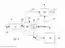
FIG. 2 is a schematic view of a power plant in an embodiment of the invention; and
FIG. 3 is a schematic view of a portion of a power plant in a preferred embodiment of the invention.
DETAILED DESCRIPTION OF THE PREFERRED EMBODIMENTS
Introduction to the Embodiments
The technical aim of the present invention therefore includes providing a power plant having selected CO2 capture units allowing a synergic operation within the power plant.
In particular the power plant has a gas turbine unit, a steam turbine unit, a CO2 capture unit and also implements flue gas recirculation, wherein all the units constituting the power plant and the recirculation cooperate to achieve a synergic effect that allows low plant and/or operating costs.
The technical aim, together with these and further aspects, are attained according to the invention by providing a power plant in accordance with the accompanying claims.
Detailed Description
The power plant has the same features already described above; the description of the plant is therefore not repeated in the following and only the most relevant components are cited; in particular in FIGS. 2 and 3 the same references used in FIG. 1 indicate equal or similar components.
The power plant 20 comprises a gas turbine unit 1 whose flue gases 8 are fed into a boiler 9 (any kind of boiler is possible, for example a reheat boiler) of a steam turbine unit 10, to be then diverted (via a diverter 21) into a recirculated flow 12 that is mixed to fresh air 7 forming a mixture 6 that is fed into the gas turbine unit compressor 2, and a discharged flow 13 that is fed into a CO2 capture unit 14. In FIG. 2 references 22, 23 indicate compressors or fans that help flow circulation.
Advantageously, the CO2 capture unit 14 is an amine based or chilled ammonia based CO2 capture unit.
The combination of these elements proved to have a synergic effect, in that all of them contribute to reduce the total costs of the plant and operation.
In fact, the flue gas recirculation allows the CO2 amount within the flue gases to be increased, this lets the size of the CO2 capture unit 14 through which the flue gases 8 has to pass through to be reduced when compared to the size theoretically needed without flue gas recirculation. In addition, with a CO2 capture unit 14 being an amine or chilled ammonia unit, a reduction of the regeneration costs was ascertained, thanks to the increased CO2 concentration within the flue gases.
Upstream of the CO2 capture unit 14, a cooler 24 is provided. Preferably, the cooler 24 is provided downstream of the boiler 9 and upstream of the diverter 21.
Advantageously, the cooler 24 is a shower cooler, i.e. a cooler wherein the flue gases rise from the bottom of a cooler casing and a cooling liquid (typically water) falls from the top of it.
The particular position of the cooler upstream of the diverter 21 allows a further cost reduction, since notwithstanding its greater size, only one cooler is needed. The particular type of cooler selected (shower cooler) allows treatment of a large amount of flue gases, with a combined cooling and filtering effect (i.e. in addition to being cooled, particles that could be generated during the combustion process are removed from the flue gases).
Typically, the flue gases 8 include NO and NO2, which are naturally generated during combustion. Since strict limits are provided for these components, their emissions should be limited by avoiding their generation during combustion and/or removing them before the flue gases 8 are discharged into the environment.
Since NO2 is known to be soluble in water to form nitric acid HNO3 according to a reaction:
3NO2+H2O→2HNO3+NO
the cooler 24 can be advantageously designed to remove a large amount of NO2 from the flue gases 8.
This allows the amount of NO2 within the flue gases emerging from the cooler 24 and supplied to the CO2 capture unit 14 to be very low (in contrast, because of the above reaction, the amount of NO increases).
Then, when the flue gases 8 pass through the CO2 capture unit 14, in addition to CO2, NO2 is also removed from the flue gases, such that the amount of NO2 within the flue gases 8 discharged into the atmosphere is very low.
In order to also reduce the amount of NO within the flue gases, an oxidizer is added within the flue gases 8, in order to make the NO react with it and form NO2; this additional NO2 is not troubling because (as already explained) it is removed from the flue gases 8 during their treatments before discharging.
In this respect the oxidizer is preferably provided upstream of and/or within the cooler 24; in other words an oxidizer is made to react with the NO of the flue gases.
FIG. 3 shows an example in which the oxidizer is added upstream of the boiler 9 (at position 25), in this case the oxidizer is preferably a gaseous oxidizer such as O2, ozone, etc.
In addition, the oxidizer may also be introduced into the flue gases 8 at position 26 (i.e. between the boiler 9 and the cooler 24); in this case both liquid and gaseous oxidizer are can be used.
Moreover, the oxidizer may also be supplied at position 28 at the top of the cooler 19 (it is a shower cooler); this solution is preferred for a liquid oxidizer.
Naturally one or combinations of the proposed solutions to make the oxidizer interact with the flue gases can be used.
In case the CO2 capture plant is a chilled ammonia based capture plant, a further synergic effect can be achieved.
In fact, typically, when a chilled ammonia CO2 capture plant is used, usually a fraction of the ammonia is drawn from the flue gases 8 and must be recuperated in a washing unit 29 by using sulphuric acid.
Advantageously, the nitric acid HNO3 gathered at the cooler 24 is supplied (via a line 30) to the washing unit 29 to neutralise the ammonia. This allows a further synergic effect to be achieved and the costs to be further reduced. The wasted water in then discharged from the washing unit 29 via a line 31.
Naturally, according to the needs the cooler 24 may also be provided between the diverter 21 and the pump 23.
Naturally, the features described may be independently provided from one another.
In practice, the materials used and the dimensions can be chosen at will according to requirements and to the state of the art.
REFERENCE NUMBERS
1 gas turbine unit
2 compressor of 1
3 combustion chamber of 1
4 turbine of 1
6 mixture
7 fresh air
8 flue gases
9 boiler
10 steam turbine unit
12 recirculated flow
13 discharged flow
14 CO2 capture unit
15 flue gas discharging
16 CO2 storing
18 cooler
19 cooler
20 power plant
21 diverter
22 compressor
23 compressor
24 cooler
25, 26, 28 oxidizer injection
29 washing unit
30 line
31 line
Claims
What is claimed is:1. A power plant (20) comprising a gas turbine unit (1) adapted to feed flue gases (8) into a boiler (9) of a steam turbine unit (10), to be then diverted into a recirculated flow (12) that is mixed with fresh air (7) forming a mixture (6) that is fed into a gas turbine unit compressor (2); and a discharged flow (13) that is fed into a CO2 capture unit (14), the CO2 capture unit (14) being an amine based or chilled ammonia based CO2 capture unit.
2. The power plant (20) as claimed in claim 1, further comprising a cooler (24) for the flue gases (8), the cooler (24) being a shower cooler, located upstream of the CO2 capture unit (14).
3. The power plant (20) as claimed in claim 2, wherein an oxidizer is provided to the flue gases (8) upstream of and/or within the cooler (24).
4. The power plant (20) as claimed in claim 2, wherein the cooler (24) is provided downstream of the boiler (9) and upstream of a diverter (21), which diverts the flue gases (8) into the recirculated flow (12) and the discharged flow (13).
5. The power plant (20) as claimed in claim 2, wherein the CO2 capture plant (14) is a chilled ammonia based capture plant comprising a washing unit (29) to neutralise ammonia drawn by the flue gases (8), wherein the washing unit (29) is fed with nitric acid gathered at the cooler (24).
6. The power plant (20) as claimed in claim 1, wherein the boiler (9) is a reheat boiler.
7. A method for operating a power plant (20) comprising a gas turbine unit (1) adapted to feed flue gases (8) into a boiler (9) of a steam turbine unit (10), the method comprising:
diverting the flue gases (8) into a recirculated flow (12) and a discharged flow (13),
mixing the recirculated flow (12) with fresh air (7) forming a mixture (6),
feeding the mixture (6) into a gas turbine unit compressor (2),
feeding the discharged flow (13) into a CO2 capture unit (14), and
operating the CO2 capture unit (14) as an amine based or chilled ammonia based CO2 capture unit.
8. The method as claimed in claim 7, further comprising cooling the flue gases (8) in a cooler (24), the cooler (24) being a shower cooler, located upstream of the CO2 capture unit (14).
9. The method as claimed in claim 8, further comprising providing an oxidizer to the flue gases (8) upstream of and/or within the cooler (24).
10. The power plant (20) as claimed in claim 8, wherein the CO2 capture plant (14) is a chilled ammonia based capture plant comprising a washing unit (29) to neutralise ammonia drawn by the flue gases (8), the method further comprising feeding the washing unit (29) with nitric acid gathered at the cooler (24).
Images & Drawings included:


Sources:
- United States Patent and Trademark Office - verify current appl. status at the USPTO↗
Recent applications in this class:
- » 20240350964 2024-10-24
RECYCLING METHOD FOR DIRECT AIR CAPTURE DEVICE - » 20240082779 2024-03-14
CLEAN WATER RECIRCULATION FOR STEAM PRODUCTION IN ROTATING PACKED BED DESORBER SYSTEM - » 20230347280 2023-11-02
FLUID TREATMENT APPARATUS - » 20220219111 2022-07-14
System and method for treating gas to fuel turbines - » 20180169569 2018-06-21
SYSTEM AND METHOD FOR A CHILLED AMMONIA-BASED CARBON DIOXIDE REMOVAL PROCESS - » 20160243492 2016-08-25
AIR CONDITIONING DEVICE - » 20140000311 2014-01-02
Method for controlling acidic compounds produced for oxy-combustion processes - » 16818281 2021-11-09
Process for desulpherization and hydrogen recovery
Recent applications for this Assignee:
- » 20180020560 2018-01-18
ASSEMBLY OF MODULES, MODULE SUPPORT AND MODULE - » 20170341339 2017-11-30
METHOD FOR OBTAINING A CONFIGURATION FOR JOINING A CERAMIC MATERIAL TO A METALLIC STRUCTURE - » 20170316904 2017-11-02
Medium- or high-voltage circuit breaker or isolator, provided with improved fixed contacts, and method of use - » 20170284378 2017-10-05
Method for operating a solar thermal power system with an economizer recirculation line - » 20170213674 2017-07-27
Circuit breaker comprising an insulating hollow tube - » 20170023243 2017-01-26
Coal rope distributor with replaceable wear components - » 20160373236 2016-12-22
Electrical power networks - » 20160373022 2016-12-22
Balancing and/or discharge resistor arrangements - » 20160352239 2016-12-01
POWER ELECTRONIC CONVERTER - » 20160298844 2016-10-13
BURNER ARRANGEMENT INCLUDING AN AIR SUPPLY WITH TWO FLOW PASSAGES