Thin fastener of heat sink
US20120106088A1
2012-05-03
12/914,903
2010-10-28
✅ Patent granted
US 8,488,322 B2
2013-07-16
-
-
Gregory Thompson
Chun-Ming Shih | HDLS IPR Services
2031-08-24
Abstract:
The heat sink fastener includes a heat conductive board and a flexible metallic wire. The heat conductive board has a pair of pivot portions. The flexible metallic wire has a pair of flexible arms and a middle portion connecting therebetween. Each flexible arm connects to the pivot portion. The pivot portion side of the heat conductive board is formed with a blocking sheet. The middle portion is provided with a bend for being blocked by the blocking sheet. When the flexible metallic wire is hooked to a ring on a circuit board, it will generate pressure to the heat conductive board resulting from the bent flexible arms and the blocked middle portion.
Assignee:
- Chaun-Choung Technology Corp. 11 🇹🇼 New Taipei, Taiwan
Applicant:
Interested in similar patents?
Get notified when new applications in this technology area are published.
Classification:
H01L23/427 » CPC main
Details of semiconductor or other solid state devices; Arrangements for cooling, heating, ventilating or temperature compensation ; Temperature sensing arrangements; Fillings or auxiliary members in containers or encapsulations selected or arranged to facilitate heating or cooling Cooling by change of state, e.g. use of heat pipes
F28D15/0275 » CPC further
Heat-exchange apparatus with the intermediate heat-transfer medium in closed tubes passing into or through the conduit walls ; Heat-exchange apparatus employing intermediate heat-transfer medium or bodies in which the medium condenses and evaporates, e.g. heat pipes Arrangements for coupling heat-pipes together or with other structures, e.g. with base blocks; Heat pipe cores
H01L23/4093 » CPC further
Details of semiconductor or other solid state devices; Arrangements for cooling, heating, ventilating or temperature compensation ; Temperature sensing arrangements; Mountings or securing means for detachable cooling or heating arrangements ; fixed by friction, plugs or springs Snap-on arrangements, e.g. clips
H01L2924/0002 » CPC further
Indexing scheme for arrangements or methods for connecting or disconnecting semiconductor or solid-state bodies as covered by; Technical content checked by a classifier Not covered by any one of groups , and
H01L2924/00 » CPC further
Indexing scheme for arrangements or methods for connecting or disconnecting semiconductor or solid-state bodies as covered by
F28F9/00 IPC
Casings; Header boxes; Auxiliary supports for elements; Auxiliary members within casings
H05K7/20 IPC
Constructional details common to different types of electric apparatus Modifications to facilitate cooling, ventilating, or heating
H05K7/20 IPC
Constructional details common to different types of electric apparatus Modifications to facilitate cooling, ventilating, or heating
F28F7/00 IPC
Elements not covered by group , or
F28D15/00 IPC
Heat-exchange apparatus with the intermediate heat-transfer medium in closed tubes passing into or through the conduit walls ; Heat-exchange apparatus employing intermediate heat-transfer medium or bodies
F28D15/00 IPC
Heat-exchange apparatus employing intermediate heat-transfer media or bodies
Description
BACKGROUND OF THE INVENTION
1. Technical Field
The invention relates to heat sinks, particularly to fasteners of heat sinks.
2. Related Art
With continuous improvement of semiconductor devices, the requirements to heat sinks also increase. On the other hand, electronic devices also constantly tend to be lighter, thinner, shorter and smaller. Thus heat sinks need not only to further improve to satisfy the requirements of heat dissipation of electronic devices, but also to be lighter and thinner than before.
Taiwan patent No. 1305825 discloses a typical heat sink fastener of the CPU (hereinafter “TW825”). TW 825 uses a heat conductive board attached on the CPU, so the heat conductive plate must exert pressure on the CPU. In TW825, the heat conductive board is fastened by four flexible pins at corners. Each flexible pin is composed of a screw and a spring. The screws must penetrate the heat conductive board and the motherboard so as to fasten the heat conductive board on the motherboard. Thus the screws must possess a specific length. On the other hand, the heat conductive board must be further provided with sleeves for being passed through by the screws. In sum, this kind of structure is relatively complicated and its overall height and weight is hard to be reduced, too. This is very disadvantageous to the thin-and light design of computers.
Taiwan patent No. M276267 discloses another similar heat sink fastener (hereinafter “TW 267”). TW267 differs from TW825 by fixing two extended plates on the heat conductive board. The heat conductive board is fixed on the circuit board by fastening the extended plates on the circuit board. Thus there still are the drawbacks the same as TW825.
SUMMARY OF THE INVENTION
An object of the invention is to provide a thin fastener of heat sink, which can efficiently simplify the structure of heat sink fastener and reduce overall height and weight. This will be advantageous to the thin and light design of electronic devices.
To accomplish the above object, the fastener of the invention includes a heat conductive board and a flexible metallic wire. The heat conductive board has a pair of pivot portions. The flexible metallic wire has a pair of flexible arms and a middle portion connecting therebetween. Each flexible arm connects to the pivot portion.
To accomplish the above object, the fastener of the invention includes a heat conductive board and a pair of flexible metallic wires. The heat conductive board has a pair of pivot portions. Each the flexible metallic wire has a pair of flexible arms and a middle portion connecting therebetween. Each flexible arm connects to the pivot portion.
The pivot portion side of the heat conductive board is formed with a blocking sheet. The middle portion is provided with a bend for being blocked by the blocking sheet. When the flexible metallic wire is hooked to a ring on a circuit board, it will generate pressure to the heat conductive board resulting from the bent flexible arms and the blocked middle portion.
BRIEF DESCRIPTION OF THE DRAWINGS
FIG. 1 is a perspective view of the first embodiment of the invention;
FIG. 2 is a schematic view of the invention and an electronic component to be mounted;
FIG. 3 is a top view of the first embodiment of the invention;
FIG. 4 is a cross-sectional view of the first embodiment of the invention;
FIG. 5 shows another shape of the heat conductive board;
FIG. 6 shows the second embodiment of the invention; and
FIG. 7 shows the third embodiment of the invention.
DETAILED DESCRIPTION OF THE INVENTION
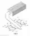
Please refer to FIG. 1, which is a perspective view of the first embodiment of the invention. Roughly, the heat sink fastener of the invention includes a heat conductive board 1 and two flexible metallic 2a,2b.
Two opposite sides of the heat conductive board 1 are separately provided with two pivot portions. In this embodiment, each the pivot portion is a pair of hollow cylinders 11a,11b;12a,12b. Each pair of hollow cylinders 11a,11b;12a,12b is arranged in a line and may be formed by curling an edge of the heat conductive board 1. A blocking sheet 13a,13b is formed between each pair of hollow cylinders 11a,11b;12a,12b. The blocking sheets 13a,13b are coplanar to the heat conductive board 1 and protrude from the two pairs of hollow cylinders 11a,11b;12a,12b.
Each of the two flexible metallic wires 2a,2b is of a U shape. It can be defined into a middle portion 23a,23b and two flexible arms 21a,22a;21b,22b. The middle portion 23a or 23b penetrates a pair of hollow cylinders 11a,11b or 12a,12b to form a pivotal connection. And an exposed portion of the middle portion 23a or 23b at the location of the blocking sheet 13a or 13b is formed with a bend 231a,231b. Preferably, the bend 231a or 231b is of a V shape. Of course, it may also be of any other proper shapes. Each the bend 231a or 231b is blocked by the blocking sheet 13a or 13b to make the middle portion 23a or 23b not able to rotate downwards. Besides, free ends of the flexible arms 21a,22a;21b,22b are preferably separately formed with hooks 211a,221a;211b,221b for being fixed on a circuit board. The top of the heat conductive board 1 may be attached by an evaporation end of a heap pipe 3. The condensation end of the heat pipe 3 may connect to a fin set 4.
Please refer to FIG. 2, which is a schematic view of the invention and an electronic component to be mounted. The heat conductive board 1 is used to be mounted on the electronic component 6 on a circuit board 5. There are four rings 51a,51b,51c,51d on the circuit board 5 around the electronic component 6. These rings 51a,51b,51c,51d are separately corresponding to the four hooks 211a,221a;211b,221b. After the heat conductive board 1 is put on the electronic component 6, the flexible arms 21a,22a;21b,22b are slightly bent to make the hooks 211a,221a,211b,221b separately pass through the rings 51a,51b,51c,51d as shown in FIGS. 3 and 4. At this time, the bends 231a,231b are blocked by the blocking sheets 13a,13b so as to exert pressure to the heat conductive board 1. As a result, the heat conductive board 1 clings to the electronic component 6 to form a very great thermal contact.
The heat sink fastener of the invention does not require any screw. The invention only employs elasticity from the deformed flexible metallic wires 2a,2b to generate pressure. Not only can the structure be simplified, but also the weight can be reduced, and even the height also can be shortened. These are advantageous to the thin and light design of electronic devices.
FIG. 5 shows another shape of the heat conductive board. The heat conductive board 1′ has relatively larger thickness which can sheathe the heat pipe 3. This can make a better thermo-conductivity between the heat conductive board 1′ and heat pipe 3 because of larger contact area and tighter connection.
FIG. 6 shows the second embodiment of the invention. In this embodiment, the flexible metallic wire 2c is of a U shape, which can be defined into a middle portion 23c and two flexible arms 21c,22c. The two flexible arms 21c,22c separately penetrate through two pairs of hollow cylinders 11a,11b;12a,12b. The middle portion 23c is exposed out of one side of the heat conductive board 1. The middle portion 23c and two free ends of the flexible arms 21c,22c are separately formed with hooks 211c,221c,231c for penetrating through rings as shown in the abovementioned embodiment. Similarly, the top of the heat conductive board 1 may be attached by a heat pipe 3 connecting with a fin set 4. In this embodiment, the flexible metallic wire 2c has three hooks 211c,221c,231c, so there should be three rings disposed on a circuit board (not shown) for being penetrated by the hooks 211c,221c,231c.
FIG. 7 shows the third embodiment of the invention. In this embodiment, two pivot portions of the heat conductive board 1″ are separately provided with two pairs of hollow cylinders 11c,11d;12c,12d. Each pair of hollow cylinders 11c,11d;12c,12d formed by stamping and is arranged in a line. Two flexible arms 21c,22c of the flexible metallic wire separately penetrate through two pairs of hollow cylinders 11c,11d;12c,12d. Similarly, the top of the heat conductive board 1 may be attached by a heat pipe 3 connecting with a fin set 4.
While the forgoing is directed to preferred embodiments of the present invention, other and further embodiments of the invention may be devised without departing from the basic scope thereof. As such, the appropriate scope of the invention is to be determined according to the claims.
Claims
What is claimed is:1. A heat sink fastener comprising:
a heat conductive board having a pair of pivot portions;
a flexible metallic wire having a pair of flexible arms and a middle portion connecting therebetween, and each the flexible arm connecting to one of the pivot portions.
2. The heat sink fastener of claim 1, wherein the flexible metallic wire is of a U shape.
3. The heat sink fastener of claim 1, wherein each the pivot portion is a hollow cylinder formed by curling an edge of the heat conductive board, and each the flexible arm penetrates through one of the hollow cylinders.
4. The heat sink fastener of claim 1, wherein free ends of the pair of flexible arms are separately formed with two hooks, and the middle portion is also formed with a hook.
5. The heat sink fastener of claim 4, further comprising three rings mounted on a circuit board for being separately penetrated by the three hooks.
6. The heat sink fastener of claim 1, wherein the heat conductive board connects a heat pipe.
7. The heat sink fastener of claim 6, wherein an end of the heat pipe is sheathed in the heat conductive board.
8. The heat sink fastener of claim 1, wherein each of the pair of pivot portions is a hollow cylinder formed by stamping, and each the flexible arm penetrates through one of the hollow cylinders.
9. A heat sink fastener comprising:
a heat conductive board having a pair of pivot portions;
a pair of flexible metallic wires, each having a pair of flexible arms and a middle portion connecting therebetween, and each the middle portion connecting to one of the pair of pivot portions.
10. The heat sink fastener of claim 9, wherein each the flexible metallic wire is of a U shape.
11. The heat sink fastener of claim 9, wherein each the pivot portion is a pair of hollow cylinders formed by curling an edge of the heat conductive board, and each the flexible arm penetrates through one of the two pairs of hollow cylinders.
12. The heat sink fastener of claim 11, wherein a blocking sheet is formed at a gap between each the pair of hollow cylinders, and each the middle portion is formed with a bend for being blocked by the blocking sheet.
13. The heat sink fastener of claim 9, wherein free ends of the two pairs of flexible arms are separately formed with four hooks.
14. The heat sink fastener of claim 13, further comprising four rings mounted on a circuit board for being separately penetrated by the four hooks.
15. The heat sink fastener of claim 9, wherein the heat conductive board connects a heat pipe.
16. The heat sink fastener of claim 15, wherein an end of the heat pipe is sheathed in the heat conductive board.
17. The heat sink fastener of claim 9, each of the pair of pivot portions is a hollow cylinder formed by stamping, and each the flexible arm penetrates through one of the hollow cylinders.
Images & Drawings included:


Sources:
- United States Patent and Trademark Office - verify current appl. status at the USPTO↗
Recent applications in this class:
- » 20250259910 2025-08-14
INTEGRATED CIRCUIT PACKAGE WITH MULTI-CHAMBERED THERMAL CONTROL DEVICE - » 20250246513 2025-07-31
Hybrid Vapor Chamber Lid - » 20250233048 2025-07-17
SEMICONDUCTOR PACKAGE AND METHOD OF MANUFACTURING THE SEMICONDUCTOR PACKAGE - » 20250233047 2025-07-17
PACKAGE STRUCTURE WITH HEAT DISSIPATION STRUCTURE HAVING ONE OR MORE VAPOR CHAMBERS OVER IC CHIPS - » 20250226287 2025-07-10
NOVEL CHIP COOLING PLATFORM BASED ON MICRO-NANO STRUCTURE - » 20250210454 2025-06-26
CONTROL UNIT - » 20250210453 2025-06-26
MICRO VAPOR CHAMBER LIDS - » 20250201663 2025-06-19
Reflowable Vapor Chamber Lid - » 20250167074 2025-05-22
PASSIVE THERMAL CONTROL LAYER FOR INTEGRATED DEVICE - » 20250157881 2025-05-15
OPTIMIZED COMBINED MICROCHANNEL AND HEAT PIPES FOR ELECTRONICS COOLING
Recent applications for this Assignee:
- » 20190339019 2019-11-07
Pressing method of heat conductive base and finished product thereof - » 20170131036 2017-05-11
Composite structure of flat heat pipe and heat conduction device thereof - » 20170023307 2017-01-26
Vapor chamber having no gas discharging protrusion and manufacturing method thereof - » 20160010926 2016-01-14
Heat plate structure - » 20140347811 2014-11-27
Portable electronic device with exposed heat dissipating mechanism - » 20140230248 2014-08-21
Method of making lightweight heat pipe - » 20130126125 2013-05-23
Thin heat pipe having recesses for fastener - » 20100078425 2010-04-01
Vane type electric heater and vane structure thereof - » 15908675 2018-12-11
Electronic device and heat dissipation structure thereof - » 14885450 2017-02-21
Heat dissipating device