Coated cutting tool for metal cutting applications generating high temperatures
US20120114442A1
2012-05-10
13/259,935
2009-06-09
✅ Patent granted
US 8,741,011 B2
2014-06-03
WO; PCT/SE2009/050697; 20090609
WO; WO2010/114448; 20101007
Archene Turner
Morgan, Lewis & Bockius LLP
2030-02-19
Abstract:
The present invention relates to a cutting tool insert comprising a body of cemented carbide, cermet, ceramics, high speed steel (HSS), polycrystalline diamond (PCD) or polycrystalline cubic boron nitride (PCBN), a hard and wear resistant coating is applied, grown by physical vapour deposition (PVD) such as cathodic arc evaporation or magnetron sputtering. Said coating comprises at least one layer of (ZrxAl1-x)N with of 0.45<x<0.85 and 0.90≦y<1.30 with a thickness between 0.5 and 10 μm. Said layer has a nanocrystalline microstructure consisting of a single cubic phase or a mixture of hexagonal and cubic phases. The insert is particularly useful in metal cutting applications generating high temperatures with improved crater wear resistance.
Inventors:
- Mats Johansson 22 🇸🇪 Linkoping, Sweden
- Magnus Oden 10 🇸🇪 Tullinge, Sweden
- Lars Hultman 19 🇸🇪 Linköping, Sweden
- Lina Rogstrom 3 🇸🇪 Linkoping, Sweden
- Lars Johnson 2 🇸🇪 Linkoping, Sweden
Assignee:
- Sandvik Intellectual Property AB 898 🇸🇪 Sandviken, Sweden
Applicant:
Interested in similar patents?
Get notified when new applications in this technology area are published.
Classification:
B23B27/148 » CPC main
Tools for turning or boring machines ; Tools of a similar kind in general; Accessories therefor; Cutting tools of which the bits or tips or cutting inserts are of special material Composition of the cutting inserts
C04B41/87 » CPC further
After-treatment of mortars, concrete, artificial stone or ceramics; Treatment of natural stone of only ceramics; Coating or impregnation with inorganic materials Ceramics
C04B41/89 » CPC further
After-treatment of mortars, concrete, artificial stone or ceramics; Treatment of natural stone of only ceramics; Coating or impregnation for obtaining at least two superposed coatings having different compositions
C23C14/0021 » CPC further
Coating by vacuum evaporation, by sputtering or by ion implantation of the coating forming material Reactive sputtering or evaporation
C23C14/0036 » CPC further
Coating by vacuum evaporation, by sputtering or by ion implantation of the coating forming material; Reactive sputtering or evaporation Reactive sputtering
C23C14/325 » CPC further
Coating by vacuum evaporation, by sputtering or by ion implantation of the coating forming material characterised by the process of coating; Vacuum evaporation by explosion; by evaporation and subsequent ionisation of the vapours, e.g. ion-plating Electric arc evaporation
C23C28/042 » CPC further
Coating for obtaining at least two superposed coatings either by methods not provided for in a single one of groups - or by combinations of methods provided for in subclasses and or only coatings of inorganic non-metallic material including a refractory ceramic layer, e.g. refractory metal oxides, ZrO, rare earth oxides
C23C28/044 » CPC further
Coating for obtaining at least two superposed coatings either by methods not provided for in a single one of groups - or by combinations of methods provided for in subclasses and or only coatings of inorganic non-metallic material coatings specially adapted for cutting tools or wear applications
C23C30/005 » CPC further
Coating with metallic material characterised only by the composition of the metallic material, i.e. not characterised by the coating process on hard metal substrates
B23B2222/80 » CPC further
Materials of tools or workpieces composed of metals, alloys or metal matrices Stainless steel
B23B2222/84 » CPC further
Materials of tools or workpieces composed of metals, alloys or metal matrices Steel
B23B2228/10 » CPC further
Properties of materials of tools or workpieces, materials of tools or workpieces applied in a specific manner Coatings
B23B2270/54 » CPC further
Details of turning, boring or drilling machines, processes or tools not otherwise provided for Methods of turning, boring or drilling not otherwise provided for
B23C2220/48 » CPC further
Details of milling processes Methods of milling not otherwise provided for
B23C2222/84 » CPC further
Materials of tools or workpieces composed of metals, alloys or metal matrices Steel
C04B2111/0025 » CPC further
Mortars, concrete or artificial stone or mixtures to prepare them, characterised by specific function, property or use; Physical properties of the materials not provided for elsewhere in Compositions or ingredients of the compositions characterised by the crystal structure
Y10T407/27 » CPC further
Cutters, for shaping comprising tool of specific chemical composition
Y10T409/303808 » CPC further
Gear cutting, milling, or planing; Milling; Process including infeeding
Y10T428/252 » CPC further
Stock material or miscellaneous articles; Web or sheet containing structurally defined element or component and including a second component containing structurally defined particles Glass or ceramic [i.e., fired or glazed clay, cement, etc.] [porcelain, quartz, etc.]
Y10T428/265 » CPC further
Stock material or miscellaneous articles; Web or sheet containing structurally defined element or component, the element or component having a specified physical dimension; Coating layer not in excess of 5 mils thick or equivalent; Up to 3 mils 1 mil or less
C04B41/5068 » CPC further
After-treatment of mortars, concrete, artificial stone or ceramics; Treatment of natural stone; Coating or impregnating e.g. injection in masonry, partial coating of green or fired ceramics, organic coating compositions for adhering together two concrete elements, with inorganic materials non-oxide ceramics; Borides, Nitrides or Silicides Titanium nitride
C04B41/52 » CPC further
After-treatment of mortars, concrete, artificial stone or ceramics; Treatment of natural stone; Coating or impregnating e.g. injection in masonry, partial coating of green or fired ceramics, organic coating compositions for adhering together two concrete elements, Multiple coating or impregnating multiple coating or impregnating with the same composition or with compositions only differing in the concentration of the constituents, is classified as single coating or impregnation
C04B41/5062 » CPC further
After-treatment of mortars, concrete, artificial stone or ceramics; Treatment of natural stone; Coating or impregnating e.g. injection in masonry, partial coating of green or fired ceramics, organic coating compositions for adhering together two concrete elements, with inorganic materials non-oxide ceramics Borides, Nitrides or Silicides
C04B41/4531 » CPC further
After-treatment of mortars, concrete, artificial stone or ceramics; Treatment of natural stone; Coating or impregnating e.g. injection in masonry, partial coating of green or fired ceramics, organic coating compositions for adhering together two concrete elements, characterised by the method of application applied from the gas phase by C.V.D.
C04B41/5063 » CPC further
After-treatment of mortars, concrete, artificial stone or ceramics; Treatment of natural stone; Coating or impregnating e.g. injection in masonry, partial coating of green or fired ceramics, organic coating compositions for adhering together two concrete elements, with inorganic materials non-oxide ceramics; Borides, Nitrides or Silicides Aluminium nitride
C04B35/00 » CPC further
Shaped ceramic products characterised by their composition ; Ceramics compositions ; Processing powders of inorganic compounds preparatory to the manufacturing of ceramic products
C04B35/52 » CPC further
Shaped ceramic products characterised by their composition ; Ceramics compositions ; Processing powders of inorganic compounds preparatory to the manufacturing of ceramic products based on non-oxide ceramics based on carbon, e.g. graphite
C04B41/009 » CPC further
After-treatment of mortars, concrete, artificial stone or ceramics; Treatment of natural stone characterised by the material treated
C04B35/5831 » CPC further
Shaped ceramic products characterised by their composition ; Ceramics compositions ; Processing powders of inorganic compounds preparatory to the manufacturing of ceramic products based on non-oxide ceramics based on borides, nitrides, or silicides based on boron nitride based on cubic boron nitrides or Wurtzitic boron nitrides, including crystal structure transformation of powder
C23C14/24 IPC
Coating by vacuum evaporation, by sputtering or by ion implantation of the coating forming material characterised by the process of coating Vacuum evaporation
C23C14/35 » CPC further
Coating by vacuum evaporation, by sputtering or by ion implantation of the coating forming material characterised by the process of coating; Sputtering by application of a magnetic field, e.g. magnetron sputtering
B23C5/16 IPC
Milling-cutters characterised by physical features other than shape
C23C14/0641 » CPC further
Coating by vacuum evaporation, by sputtering or by ion implantation of the coating forming material characterised by the coating material Nitrides
B23B27/14 » CPC further
Tools for turning or boring machines ; Tools of a similar kind in general; Accessories therefor Cutting tools of which the bits or tips or cutting inserts are of special material
C23C14/06 IPC
Coating by vacuum evaporation, by sputtering or by ion implantation of the coating forming material characterised by the coating material
Description
BACKGROUND OF THE INVENTION
The present invention relates to a cutting tool insert for machining by chip removal and wear resistant coating comprising at least one (Zr,Al)N layer with high Zr content grown by physical vapour deposition (PVD) and preferably by cathodic arc evaporation or magnetron sputtering. This insert is particularly useful in metal cutting applications generating high temperatures, e.g., machining of steel, stainless steel and hardened steel.
Zr1-xAlxN (0≦x≦1.0) layers have been synthesized by the cathodic arc evaporation using alloyed and/or metal cathodes, H. Hasegawa et al, Surf. Coat. Tech. 200 (2005). The peaks of Zr1-xAlxN (x=0.37) showed a NaCl structure that changed to a wurtzite structure at x=0.50.
EP 1 785 504 discloses a surface-coated base material and a high hardness coating formed on or over said base material. Said high hardness coating comprises a coating layer containing a nitride compound with Al as main component and at least one element selected from the group consisting of Zr, Hf, Pd, Ir and the rare earth elements.
JP 04-017664 discloses a gradient layer consisting of at least one kind among the carbide, nitride and carbonitride of ZrxAl1-x (0.5≦x≦1.0) in which the Al concentration is continuously or stepwise changed from the interface with the base material toward the surface of the layer.
EP 1 935 999 discloses a cemented carbide end-milling tool with a wear resistant coating.
The wear resistant coating comprises a first layer of a PVD AlMe nitride or carbonitride where Me is Zr, V, Nb, Cr or Ti with an atomic fraction of Al to Me between 1.20 and 1.50 and a second layer of PVD AlMe nitride or carbonitride where Me is Zr, V, Nb, Cr or Ti with an atomic fraction of Al to Me between 1.30 and 1.70.
The trends towards dry-work processes for environmental protection, i.e., metal cutting operation without using cutting fluids (lubricants) and accelerated machining speed with improved process put even higher demands on the characteristics of the tool materials due to an increased tool cutting-edge temperature. In particular, coating stability at high temperatures, e.g., oxidation- and wear-resistance, has become even more crucial.
It is an object of the present invention to provide a coated cutting tool insert with improved performance in metal cutting applications at elevated temperatures.
It has been found that a high Zr content in superstoichiometric (Zr,Al)N layers leads to improved high temperature properties and in particular improved crater wear resistance during metal cutting.
BRIEF DESCRIPTION OF THE DRAWINGS
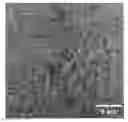
FIG. 1; A scanning electron microscope (SEM) micrograph of a fractured (Al,Zr)N layer.
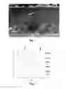
FIG. 2; X-ray diffraction patterns vs. heat treatment temperature.
FIG. 3; Hardness vs. heat treatment temperature and composition, x in (ZrxAl1-x)N.
FIG. 4; A high resolution transmission electron microscope (TEM) cross sectional micrograph of a (Zr,Al)N layer.
DETAILED DESCRIPTION OF THE INVENTION
According to the present invention, there is provided a cutting tool for machining by chip removal comprising a body of a hard alloy of cemented carbide, cermet, ceramics, high speed steel (HSS), polycrystalline diamond (PCD) or polycrystalline cubic boron nitride (PCBN), preferably cemented carbide and cermet, onto which a wear resistant coating is deposited comprising at least one (ZrxAl1-x)Ny layer with 0.45<x<0.85, preferably 0.50<x<0.75, and 0.90≦y<1.30, preferably 1.00<y<1.25, more preferably 1.00<y<1.20, as determined by, e.g., EDS or WDS techniques, consisting of a single cubic phase or a single hexagonal phase or a mixture thereof, preferably a mixture of cubic and hexagonal phases with predominantly cubic phase, as determined by X-ray diffraction. The elemental composition, x and y, is, within the measurement accuracy, preferably with a variation less than 10% throughout the layer. Variation of the composition may also occur due to normal process variations during deposition such as, e.g., rotation of the insert holder during deposition.
Said layer is 0.5 to 10 gμ, preferably 0.5 to 5 μm thick, and has a nanocrystalline microstructure with an average crystallite size of <100 nm, preferably <50 nm, most preferably <25 nm, as determined by high resolution cross sectional transmission electron microscopy of a middle region of the layer, i.e., a region within 30 to 70% of the thickness in the growth direction. Said average crystallite size is the average from measuring the size of at least ten adjacent crystallites.
Said as-deposited (Zr,Al)N layer with its nanocrystalline structure has a hardness >23 GPa and preferably <35 GPa.
The body may further be coated with an inner single- and/or multilayer coating of, preferably TiN, TiC, Ti(C,N) or (Ti,Al)N, most preferably TiN or (Ti,Al)N, and/or an outer single- and/or multilayer coating of, preferably TiN, TiC, Ti(C,N), (Ti,Al)N or oxides, most preferably TiN or (Ti,Al)N, to a total coating thickness, including the (Zr,Al)N layer, of 0.7 to 20 preferably 1 to 10 μm, and most preferably 2 to 7 μm.
In one embodiment, (Zr,Al)N is deposited by cathodic arc evaporation from cathodes resulting in the desired layer composition, preferably by evaporation of an alloyed cathode, at the following conditions: an evaporation current between 50 and 200 A, a bias between 0 and −300 V, preferably between −10 and −150 V, and a temperature between 200 and 800° C., preferably between 300 and 600° C., in a mixed Ar+N2 atmosphere, preferably in pure N2, and at a total pressure between 1.0 and 7.0 Pa, preferably between 1.5 and 4.0 Pa.
In a second embodiment, (Zr,Al)N is deposited by magnetron sputtering from targets resulting in the desired layer composition, preferably by sputtering from an alloyed or composite target, at the following conditions: a power density applied to the sputter cathode between 0.5 and 15 W/cm2, preferably between 1 and 5 W/cm2, a bias between 0 and −300 V, preferably between −10 and −150 V, and a temperature between 200 and 800° C., preferably between 300 and 600° C., in a mixed Ar+N2 or pure N2 atmosphere and at a total pressure between 0.1 and 7.0 Pa, preferably between 0.1 and 2.5 Pa.
The invention also relates to the use of cutting tool inserts according to the above for machining of steel, stainless steel and hardened steel at cutting speeds of 50-500 m/min, preferably 75-400 m/min, with an average feed, per tooth in the case of milling, of 0.08-0.5 mm, preferably 0.1-0.4 mm, depending on cutting speed and insert geometry.
Example 1
Cemented carbide inserts with composition 94 wt % WC-6 wt % Co (fine grained) were used.
Before deposition, the inserts were cleaned according to standard practice. The system was evacuated to a pressure of less than 0.08 Pa, after which the inserts were sputter cleaned with Ar ions. Single (ZrxAl1-x)Ny layers were grown using cathodic arc evaporation using alloyed (Zr,Al) cathodes. The layers were grown at 400° C., in pure N2 atmosphere at a total pressure of 2.5 Pa, using a bias of −100 V and an evaporation current between 100 A and 200 A to a total thickness of 3 μm, resulting in layer compositions according to table 1.
FIG. 1 shows a SEM micrograph of a typical layer in (fractured) cross-section according to the invention with a glassy appearance common for nanocrystalline structures.
The metal composition, x, of the (ZrxAl1-x)Ny layers was obtained by energy dispersive spectroscopy (EDS) analysis area using a LEO Ultra 55 scanning electron microscope with a Thermo Noran EDS. Industrial standards and ZAF correction were used for the quantitative analysis and evaluated using a Noran System Six (NSS version 2) software (see table 1).
The nitrogen content, y, for some of the (ZrxAl1-x)Ny layers was obtained by Time of Flight Elastic Recoil Detection Analysis (ERDA) using an incident 40 MeV Iodine ion beam. From the elemental depth profiles achieved the y-value was calculated using data down to a depth of 300 nm in the layer (see table 1).
| TABLE 1 | ||
| Layer | x | y |
| 1 | 1.00 | — |
| 2 | 0.83 | — |
| 3 | 0.83 | 1.00 |
| 4 | 0.81 | — |
| 5 | 0.74 | — |
| 6 | 0.70 | 1.09 |
| 7 | 0.67 | — |
| 8 | 0.52 | — |
| 9 | 0.50 | 1.20 |
| 10 | 0.50 | — |
| 11 | 0.35 | — |
| 12 | 0.35 | 1.27 |
| 13 | 0.40 | — |
| 14 | 0.34 | — |
| 15 | 0.26 | 1.20 |
| 16 | 0.24 | — |
In order to simulate age hardening, i.e., an increased hardening effect of the coating with time, accelerated test conditions were used by conducting controlled isothermal heat treatments of the inserts in inert Ar atmosphere up to 1200° C. for 120 min. Also, this is the typical temperature close to the cutting edge of the insert during metal machining.
The XRD patterns of the as-deposited layers and heat treated layers were obtained using Cu K alpha radiation and a θ-2θ configuration. The layer peaks, typically, are rather broad characteristic of a nanocrystalline structure. Moreover, the fraction of the cubic phase increases with increasing heat treatment temperatures and observed by more well defined diffraction peaks. As an example, FIG. 2 shows the XRD result of a the (Zr0.67Al0.33)N layer as a function of heat treatment temperature where the cubic phase is indexed with (111) and (200), the insert with (S) and the hexagonal phase with dotted lines. As apparent from the figure, the as-deposited layer (marked with 25° C.) show a mixture of nanocrystalline hexagonal and cubic structured (Zr,Al)N.
Hardness data was estimated by the nanoindentation technique of the layers using a UMIS nanoindentation system with a Berkovich diamond tip and a maximum tip load of 25 mN. Indentations were made on polished surfaces. FIG. 3 shows the hardness (H) of (ZrxAl1-x)N layers as a function of heat treatment and composition, x. For x>0.50, an unexpected increase of the age hardening is obtained. Specifically, the increase in hardness for x=0.67 is more than 25%, i.e., with values from 25 to 33 GPa.
Cross-sectional high resolution transmission electron microscopy (TEM) was used to study the microstructure of the layers with a FEI Technai G2 TF 20 UT operated at 200 kV. The sample preparation comprised standard mechanical grinding/polishing and ion-beam sputtering. FIG. 4 shows that the layer exhibits a nanocrystalline microstructure with an average crystallite size of <25 nm.
Example 2
Inserts from example 1 were tested according to:
Geometry: CNMA 120408-KR
Application: Longitudinal turning
Work piece material: SS1672
Cutting speed: 240 m/min
Feed: 0.2 mm/rev
Depth of cut: 2 mm
Crater wear was measured as the crater area in mm2 after 5 min of turning with the following results.
| TABLE 2 | ||
| Layer | X in (ZrxAl1−x)N | Crater Wear (mm2) |
| 1 | 1.00 | — |
| 2 | 0.83 | — |
| 3 | 0.83 | <0.05 |
| 4 | 0.81 | — |
| 5 | 0.74 | — |
| 6 | 0.70 | — |
| 7 | 0.67 | <0.05 |
| 8 | 0.52 | — |
| 9 | 0.50 | <0.05 |
| 10 | 0.50 | — |
| 11 | 0.35 | — |
| 12 | 0.35 | 0.2 |
| 13 | 0.40 | — |
| 14 | 0.34 | — |
| 15 | 0.26 | — |
| 16 | 0.24 | 0.25 |
A crater wear <0.1 with the selected cutting data is satisfactory.
Claims
1. A cutting tool insert comprising a body of cemented carbide, cermet, ceramics, high speed steel (HSS), polycrystalline diamond (PCD) or polycrystalline cubic boron nitride (PCBN), a hard and wear resistant coating is applied, said coating comprising at least one layer wherein said layer consists of (ZrxAl1-x)Ny with 0.45<x<0.85 and 0.90≦y<1.30 with a thickness between 0.5 and 10 μm, preferably between 0.5 and 5 μm, and a nanocrystalline microstructure consisting of a single cubic phase or a mixture of hexagonal and cubic phases.
2. A cutting tool insert according to claim 1 wherein the average crystallite size of <100 nm, preferably <50 nm.
3. A cutting tool insert according to claim 1 wherein 0.50<x<0.75 and 1.00<y<1.25.
4. A cutting tool insert according to claim 1 wherein 1.00<y<1.20.
5. A cutting tool insert according to claim 1 wherein the elemental composition, x and y, is, within the measurement accuracy, preferably with a variation less than 10% throughout the layer.
6. A cutting tool insert according to claim 1 wherein said layer has a hardness >23 GPa.
7. A cutting tool insert according to claim 1 wherein said body having an inner single- and/or multilayer coating of, preferably TiN, TiC, Ti(C,N) or (Ti,Al)N, most preferably TiN or (Ti,Al)N, and/or an outer single- and/or multilayer coating of, preferably TiN, TiC, Ti(C,N), (Ti,Al)N or oxides, most preferably TiN or (Ti,Al)N, to a total coating thickness, including the (Zr,Al)N layer, of 0.7 to 20 μm, preferably 1 to 10 μm, and most preferably 2 to 7 μm.
8. A method of making a cutting tool insert according to claim 1 comprising: depositing said (Zr,Al)N layer by cathodic arc evaporation from cathodes yielding the desired layer composition, preferably by evaporation of an alloyed cathode, with the following conditions: an evaporation current between 50 and 200 A, a bias between 0 and −300 V, preferably between −10 and −150 V, and a temperature between 200 and 800° C., preferably between 300 and 600° C., in a mixed Ar+N2 atmosphere, preferably in a pure N2, and at a total pressure between 1.0 and 7.0 Pa, preferably between 1.5 and 4.0 Pa.
9. A method of making a cutting tool insert according to claim 1 comprising: depositing said (Zr,Al)N layer by magnetron sputtering from targets yielding the desired layer composition, preferably by sputtering from an alloyed or composite target, with the following conditions: a power density applied to the sputter cathode between 0.5 and 15 W/cm2, preferably between 1 and 5 W/cm2, a bias between 0 and −300 V, preferably between −10 and −150 V, and a temperature between 200 and 800° C., preferably between 300 and 600° C., in a mixed Ar+N2 or pure N2 atmosphere at a total pressure between 0.1 and 7.0 Pa, preferably between 0.1 and 2.5 Pa.
10. A method of using a cutting tool insert according to claim 1 comprising: using the cutting tool for metal cutting applications in steel, stainless steel and hardened steel at cutting speeds of 50-500 m/min, preferably 75-400 m/min, with an average feed, per tooth in the case of milling, of 0.08-0.5 mm, preferably 0.1-0.4 mm depending on cutting speed and insert geometry.
Images & Drawings included:


Sources:
- United States Patent and Trademark Office - verify current appl. status at the USPTO↗
Similar patent applications:
Recent applications in this class:
- » 20250269435 2025-08-28
COATED CUTTING TOOL - » 20250262673 2025-08-21
COATED CUTTING TOOL - » 20250242417 2025-07-31
COATED TOOL AND CUTTING TOOL - » 20250242416 2025-07-31
CEMENTED CARBIDE AND CUTTING TOOL - » 20250242415 2025-07-31
CEMENTED CARBIDE AND CUTTING TOOL - » 20250214148 2025-07-03
COATED TOOL AND CUTTING TOOL - » 20250214147 2025-07-03
SURFACE-COATED CUTTING TOOL - » 20250205789 2025-06-26
SURFACE-COATED CUTTING TOOL - » 20250205788 2025-06-26
CEMENTED CARBIDE AND COATED TOOL AND CUTTING TOOL EACH USING THE SAME - » 20250187081 2025-06-12
POLYCRYSTALLINE DIAMOND ELEMENT INCLUDING AT LEAST ONE LEACHING FEATURE, CUTTING TOOL INSERTS AND SYSTEMS INCORPORATING SAME, AND RELATED METHODS
Recent applications for this Assignee:
- » 20240141466 2024-05-02
DUPLEX STAINLESS STEEL AND FORMED OBJECT THEREOF - » 20230405601 2023-12-21
MOBILE BULK MATERIAL PROCESSING MACHINE WITH DEMOUNTABLE HANGING ASSEMBLY - » 20230191508 2023-06-22
Milling insert and a side and face milling tool - » 20230182187 2023-06-15
Tube and a method of manufacturing a tube - » 20220339688 2022-10-27
Tube and a method of manufacturing a tube - » 20220288683 2022-09-15
METHOD OF MAKING CERMET OR CEMENTED CARBIDE POWDER - » 20220112585 2022-04-14
DUPLEX STAINLESS STEEL AND FORMED OBJECT THEREOF - » 20220074026 2022-03-10
NEW USE OF A NICKEL-BASED ALLOY - » 20210354205 2021-11-18
Tool body including a damping apparatus and a machining tool having such a tool body - » 20210331179 2021-10-28
Torque reaction pulley for an inertia cone crusher