Component module for a reduced pressure treatment system
US20120116331A1
2012-05-10
13/350,615
2012-01-13
✅ Patent granted
US 8,786,999 B2
2014-07-22
-
-
Stephen W Jackson
2032-06-10
Abstract:
A reduced pressure treatment system includes a control unit having a control system and a reduced pressure source. The reduced pressure treatment system further includes a manifold unit in fluid communication with the reduced pressure source and a component module to augment treatment. The component module is configured to communicate with the control system of the control unit, and the component module includes a first mounting region configured to be coupled to a complimentary mounting region of the control unit. The component module further includes a second mounting region identical to the complimentary mounting region of the control unit to allow a second component module to be coupled to the first component module.
Inventors:
- Timothy Mark Robinson 168 🇬🇧 Basingstoke, United Kingdom
- Christopher Brian Locke 678 🇬🇧 Bournemouth, United Kingdom
- Mark Stephen James Beard 33 🇬🇧 Ferndown, United Kingdom
- Mark Stephen James Beard 4 🇬🇧 West Moors, United Kingdom
- Aldan Marcus Tout 1 🇬🇧 Nomansland, United Kingdom
Assignee:
- KCI Licensing, Inc. 978 🇺🇸 San Antonio, TX, United States
Applicant:
Interested in similar patents?
Get notified when new applications in this technology area are published.
Classification:
A61M1/90 » CPC main
Suction or pumping devices for medical purposes; Devices for carrying-off, for treatment of, or for carrying-over, body-liquids; Drainage systems Negative pressure wound therapy devices, i.e. devices for applying suction to a wound to promote healing, e.g. including a vacuum dressing
A61H9/0057 » CPC further
Pneumatic or hydraulic massage; Pneumatic massage Suction
A61M1/0001 » CPC further
Suction or pumping devices for medical purposes; Devices for carrying-off, for treatment of, or for carrying-over, body-liquids; Drainage systems Containers for suction drainage, e.g. rigid containers
A61M1/0023 » CPC further
Suction or pumping devices for medical purposes; Devices for carrying-off, for treatment of, or for carrying-over, body-liquids; Drainage systems Suction drainage systems
A61M1/604 » CPC further
Suction or pumping devices for medical purposes; Devices for carrying-off, for treatment of, or for carrying-over, body-liquids; Drainage systems; Containers for suction drainage, adapted to be used with an external suction source Bag or liner in a rigid container, with suction applied to both
A61M1/73 » CPC further
Suction or pumping devices for medical purposes; Devices for carrying-off, for treatment of, or for carrying-over, body-liquids; Drainage systems; Suction drainage systems comprising sensors or indicators for physical values
A61M1/732 » CPC further
Suction or pumping devices for medical purposes; Devices for carrying-off, for treatment of, or for carrying-over, body-liquids; Drainage systems; Suction drainage systems comprising sensors or indicators for physical values Visual indicating means for vacuum pressure
A61M1/74 » CPC further
Suction or pumping devices for medical purposes; Devices for carrying-off, for treatment of, or for carrying-over, body-liquids; Drainage systems; Suction drainage systems Suction control
A61M5/1415 » CPC further
Devices for bringing media into the body in a subcutaneous, intra-vascular or intramuscular way; Accessories therefor, e.g. filling or cleaning devices, arm-rests; Infusion devices, e.g. infusing by gravity; Blood infusion; Accessories therefor; Hanging-up devices Stands, brackets or the like for supporting infusion accessories
A61N1/0468 » CPC further
Electrotherapy; Circuits therefor; Details; Electrodes for external use; Use-related aspects Specially adapted for promoting wound healing
A61N5/0616 » CPC further
Radiation therapy using light; Apparatus adapted for a specific treatment Skin treatment other than tanning
F16M11/046 » CPC further
Stands or trestles as supports for apparatus or articles placed thereon Stands for scientific apparatus such as gravitational force meters; Heads; Means for attachment of apparatus; Means allowing adjustment of the apparatus relatively to the stand; Allowing translations adapted to upward-downward translation movement
F16M11/048 » CPC further
Stands or trestles as supports for apparatus or articles placed thereon Stands for scientific apparatus such as gravitational force meters; Heads; Means for attachment of apparatus; Means allowing adjustment of the apparatus relatively to the stand; Allowing translations adapted to forward-backward translation movement
F16M13/02 » CPC further
Other supports for positioning apparatus or articles ; Means for steadying hand-held apparatus or articles for supporting on, or attaching to, an object, e.g. tree, gate, window-frame, cycle
G01F23/14 » CPC further
Indicating or measuring liquid level or level of fluent solid material, e.g. indicating in terms of volume or indicating by means of an alarm by measurement of pressure
A61H2201/5056 » CPC further
Characteristics of apparatus not provided for in the preceding codes; Control means thereof pneumatically controlled
A61M2205/12 » CPC further
General characteristics of the apparatus with interchangeable cassettes forming partially or totally the fluid circuit
A61M2205/15 » CPC further
General characteristics of the apparatus Detection of leaks
A61M2205/18 » CPC further
General characteristics of the apparatus with alarm
A61M2205/33 » CPC further
General characteristics of the apparatus Controlling, regulating or measuring
A61M2205/3327 » CPC further
General characteristics of the apparatus; Controlling, regulating or measuring Measuring
A61M2205/3331 » CPC further
General characteristics of the apparatus; Controlling, regulating or measuring Pressure; Flow
A61M2205/3334 » CPC further
General characteristics of the apparatus; Controlling, regulating or measuring; Pressure; Flow Measuring or controlling the flow rate
A61M2205/3337 » CPC further
General characteristics of the apparatus; Controlling, regulating or measuring; Pressure; Flow Controlling, regulating pressure or flow by means of a valve by-passing a pump
A61M2205/3344 » CPC further
General characteristics of the apparatus; Controlling, regulating or measuring; Pressure; Flow Measuring or controlling pressure at the body treatment site
A61M2205/3379 » CPC further
General characteristics of the apparatus; Controlling, regulating or measuring Masses, volumes, levels of fluids in reservoirs, flow rates
A61M2205/3382 » CPC further
General characteristics of the apparatus; Controlling, regulating or measuring; Masses, volumes, levels of fluids in reservoirs, flow rates Upper level detectors
A61M2205/35 » CPC further
General characteristics of the apparatus Communication
A61M2205/3584 » CPC further
General characteristics of the apparatus; Communication with non implanted data transmission devices, e.g. using external transmitter or receiver using modem, internet or bluetooth
A61M2205/43 » CPC further
General characteristics of the apparatus making noise when used correctly
A61M2205/50 » CPC further
General characteristics of the apparatus with microprocessors or computers
A61M2205/502 » CPC further
General characteristics of the apparatus with microprocessors or computers User interfaces, e.g. screens or keyboards
A61M2205/505 » CPC further
General characteristics of the apparatus with microprocessors or computers; User interfaces, e.g. screens or keyboards Touch-screens; Virtual keyboard or keypads; Virtual buttons; Soft keys; Mouse touches
A61M2205/52 » CPC further
General characteristics of the apparatus with microprocessors or computers with memories providing a history of measured variating parameters of apparatus or patient
A61M2205/581 » CPC further
General characteristics of the apparatus; Means for facilitating use, e.g. by people with impaired vision by audible feedback
A61M2205/583 » CPC further
General characteristics of the apparatus; Means for facilitating use, e.g. by people with impaired vision by visual feedback
A61N2005/0661 » CPC further
Radiation therapy using light characterised by the wavelength of light used ultra-violet
F16M2200/027 » CPC further
Details of stands or supports; Locking means for translational movement by friction
Y02A90/10 » CPC further
Technologies having an indirect contribution to adaptation to climate change Information and communication technologies [ICT] supporting adaptation to climate change, e.g. for weather forecasting or climate simulation
A61M1/00 » CPC further
Suction or pumping devices for medical purposes; Devices for carrying-off, for treatment of, or for carrying-over, body-liquids; Drainage systems
H01H47/00 IPC
Circuit arrangements not adapted to a particular application of the relay and designed to obtain desired operating characteristics or to provide energising current
Description
CROSS-REFERENCE TO RELATED APPLICATIONS
This application is a continuation of U.S. patent application Ser. No. 12/986,974, filed Jan. 7, 2011, which is a continuation of U.S. patent application Ser. No. 11/901,602, filed Sep. 18, 2007, now U.S. Pat. No. 7,876,546, which claims the benefit of U.S. Provisional Application No. 60/845,993, filed Sep. 19, 2006, both of which are hereby incorporated by reference.
BACKGROUND OF THE INVENTION
1. Field of the Invention
The present invention relates generally to tissue treatment systems and in particular to a component module for a reduced pressure treatment system.
2. Description of Related Art
Clinical studies and practice have shown that providing a reduced pressure in proximity to a tissue site augments and accelerates the growth of new tissue at the tissue site. The applications of this phenomenon are numerous, but application of reduced pressure has been particularly successful in treating wounds. This treatment (frequently referred to in the medical community as “negative pressure wound therapy,” “reduced pressure therapy,” or “vacuum therapy”) provides a number of benefits, including faster healing and increased formulation of granulation tissue. Typically, reduced pressure is applied to tissue through a porous pad or other manifold unit. The porous pad contains cells or pores that are capable of distributing reduced pressure to the tissue and channeling fluids that are drawn from the tissue. The porous pad often is incorporated into a dressing having other components that facilitate treatment.
While existing reduced pressure treatment systems have enjoyed wide commercial and medical success, it would be advantageous to expand the functionality of these systems to provide a more comprehensive treatment regimen.
A need exists, therefore, for an expandable reduced pressure treatment system that allows component modules to be combined with the expandable reduced pressure treatment system and other modules to provide additional treatment features and options.
BRIEF SUMMARY OF THE INVENTION
The limitations of conventional reduced pressure treatment systems are improved by the systems and methods described herein. In one embodiment, a reduced pressure treatment system for treating a tissue site of a patient includes a control unit having a control system and a reduced pressure source. The reduced pressure treatment system further includes a manifold unit in fluid communication with the reduced pressure source and a component module to augment treatment. The component module is configured to communicate with the control system of the control unit, and the component module includes a first mounting region configured to be coupled to a complimentary mounting region of the control unit. The component module further includes a second mounting region identical to the complimentary mounting region of the control unit to allow a second component module to be coupled to the first component module.
In another embodiment, a reduced pressure treatment system for treating a tissue site of a patient includes a control unit having a control system and a reduced pressure source. A manifold unit is in fluid communication with the reduced pressure source, and a plurality of component modules are provided to augment treatment. Each of the plurality of component modules is configured to communicate with the control system, and at least one of the plurality of components modules is configured to be coupled to both the control unit and another of the plurality of component modules.
Other objects, features, and advantages of the embodiment described herein will become apparent with reference to the drawings and detailed description that follow.
BRIEF DESCRIPTION OF THE DRAWINGS
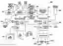
FIG. 1 is a schematic diagram of a reduced pressure treatment system according to an embodiment of the present invention;
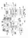
FIG. 2 is a block diagram of an exemplary control system of a reduced pressure control unit according to an embodiment of the present invention;
FIG. 3 illustrates a front perspective view of one embodiment of a control unit that houses the control system of FIG. 2;
FIG. 4 illustrates an enlarged partial cross-section view of a control unit similar to the control unit of FIG. 3 along line 4-4;
FIG. 5 illustrates an enlarged partial cross-section view of a control unit similar to the control unit of FIG. 3 along line 5-5;
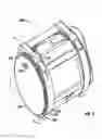
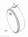
FIG. 6 illustrates a perspective view of a first end of a component module according to an embodiment of the present invention;
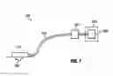
FIG. 7 illustrates a perspective view of a second end of the component module of FIG. 6;
FIG. 8 illustrates a perspective view of the first end of the component module of FIG. 6 with extended latches;
FIG. 9 illustrates a perspective view of the second end of the component module of FIG. 6 with extended latches; and
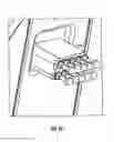
FIG. 10 illustrates an enlarged perspective view of a communication plug of the component module of FIG. 6.
DETAILED DESCRIPTION OF THE PREFERRED EMBODIMENT
In the following detailed description of the preferred embodiments, reference is made to the accompanying drawings that form a part hereof, and in which is shown by way of illustration specific preferred embodiments in which the invention may be practiced. These embodiments are described in sufficient detail to enable those skilled in the art to practice the invention, and it is understood that other embodiments may be utilized and that logical structural, mechanical, and electrical changes may be made without departing from the spirit or scope of the invention. To avoid detail not necessary to enable those skilled in the art to practice the invention, the description may omit certain information known to those skilled in the art. The following detailed description is, therefore, not to be taken in a limiting sense, and the scope of the present invention is defined only by the appended claims.
In the context of this specification, the term “reduced pressure” generally refers to a pressure less than the ambient pressure at a tissue site that is being subjected to treatment. In most cases, this reduced pressure will be less than the atmospheric pressure of the location at which the patient is located. Although the terms “vacuum” and “negative pressure” may be used to describe the pressure applied to the tissue site, the actual pressure applied to the tissue site may be significantly less than the pressure normally associated with a complete vacuum. Consistent with this nomenclature, an increase in reduced pressure or vacuum pressure refers to a relative reduction of absolute pressure, while a decrease in reduced pressure or vacuum pressure refers to a relative increase of absolute pressure.
FIG. 1 is a schematic diagram of a reduced pressure treatment system 100 according to the present invention. The reduced pressure treatment system 100 comprises a dressing 110, which generally includes a manifold unit that is applied to, or within, a tissue site 120 for treatment. The dressing 110 is fluidly connected to a reduced pressure source 160 by a conduit 130. In certain embodiments, the reduced pressure source 160 may be integrated with a reduced pressure control unit 140, as described below, and the reduced pressure treatment system 100 may also include a canister 150 for collecting liquid and other non-gaseous exudates extracted from the tissue site.
FIG. 2 is a block diagram of an exemplary control system 200 of the reduced pressure control unit 140. The control system 200 includes a treatment controller 202 and a graphical user interface (GUI) controller 204. The treatment controller 202 may include one or more processors 206 that execute software 208. The processor(s) 206 may be in communication with a memory 210 and input/output (I/O) unit 212. The software 208 may be configured to control a number of different operations of the reduced pressure treatment system 100, such as controlling tissue treatment, monitoring sensors and generating alarms and performing communications with systems and devices external to the control unit 140 in conjunction with the I/O unit 212 and GUI controller 204. It should be understood that the software 208 may further be configured to perform different and/or other functions.
The I/O unit 212 may enable the control system 200 to communicate with external modules, systems, and networks, for example. In one embodiment, the I/O unit 212 may operate in conjunction with a controller area network (CAN) or modified CAN, as described further herein. The processor 206 may further execute software to receive and process CAN data being received via the I/O unit 212.
A storage unit 214, such as a disk drive or storage medium, may be in communication with the treatment controller 202. Databases 216a-216n (collectively 216) may be used to store treatment or other information. The databases may be configured as relational databases or otherwise. Other information, such as software, may be stored on the storage unit 214.
The GUI controller 204 may include one or more processors 218 that execute software 220. The software 220 may be configured to generate a graphical user interface with which an operator, patient, technician, or other user may interface to control the system 100. The processor 218 may be in communication with a memory 222, I/O unit 224, and display driver 226. The memory 222 may store current parameters associated with displaying the GUI. For example, if the GUI is being used to display a particular screen shot, the screen shot may be stored in the memory 222. The I/O unit 224 may be used to interface with the treatment controller 202 and other devices.
A display and touch screen assembly 228 may be connected to the GUI controller 204 and be used to display the GUI generated by the GUI controller 204. The screen 228 enables an operator to merely touch the screen with his or her finger or stylus, as understood in the art, to interface with the GUI. By providing a touch screen, inclusion of a keyboard or keypad may be avoided. However, it should be understood that an external keyboard or keypad may be utilized in accordance with the principles of the present invention. A backlight inverter 230 may be connected to the GUI controller 204 and screen assembly 228. Alternatively, the backlight inverter 230 may be incorporated into the screen assembly 228. In operation, the backlight inverter may enable the screen assembly 228 to be inverted for different ambient lighting conditions. For example, a user of the system 100 may be treating a patient at night and use backlight inverter 230 to selectively turn on the backlight of the screen assembly 228 so that he or she can see the GUI better. Alternatively, the backlight inverter may be used to turn the light on the screen assembly 228 off at night to allow a patient to sleep in a darker environment.
A speaker 232 may be in communication with the GUI controller 204. The speaker may be used to provide sound notification to the user when action is required, or when an alarm condition has occurred.
A unified display interface (UDI) 234 may be utilized in accordance with the principles of the present invention. The UDI 234 may be used as a digital video interface to assist with video presentation. In addition, a number of communication ports 236 may be provided to enable a user to connect external devices to the control system 200. For example, the input ports 236 may include a CAN port 236a to enable the control system 200 to interface with other treatment systems, memory card port 236b to enable a user to transport data from one device to another, universal serial bus (USB) port to enable an operator to connect devices to the control system 200, such as printers, and Infrared Data Association (IrDA) port 236d to enable a user to interface other devices configured with an IrDA port to the system. It should be understood that other communication ports currently available or available in the future may be utilized in accordance with the principles of the present invention. For example, a communication port for connecting to a local or wide area network may be provided to enable a user to connect the control system 200 to a network.
A controller area network is a communication bus that was originally developed for automotive applications in the early 1980s. The CAN protocol was internationally standardized in 1993 as ISO 11898-1 and includes a data link of the seven layer IOS/OSI reference model. CAN, which is now available from a large number of semiconductor manufacturers in hardware form, provides two communication services: (i) sending a message (data frame transmission) and (ii) requesting a message (remote transmission request, RTR). All other services, such as error signaling and automatic re-transmission of erroneous frames, are user-transparent, which means that the CAN circuitry automatically performs these services without the need for specific programming.
A CAN controller is comparable to a printer or typewriter. Language, grammar, and vocabulary is defined for a particular use. CAN provides a multi-master hierarchy that allows for building of intelligent and redundant systems. The use of CAN with the tissue treatment system enables additional component modules, as described further herein, to operate in conjunction with the system. The component modules may operate as nodes, where each node on the CAN receives messages and decides whether a message is relevant. Data integrity is maintained because all devices in the system receive the same information. CAN also provides sophisticated error detection mechanisms and re-transmission of faulty messages.
In one embodiment, the language, grammar, and vocabulary may be customized for the system so that only devices that have the same language, grammar, and vocabulary can communicate with the system. By operating with such a customized or proprietary system, control over the quality of modules and devices that interface with the system may be maintained.
Referring still to FIG. 2, in operation, the communication ports 236 may be utilized to enable users to import or export data to and from the control system 200. For example, patient information, treatment information, and images associated with patient wounds may be communicated over a communication port 236. Other information, including software updates, may be communicated over one or more communication ports 236.
A lithium-ion (Li-Ion) battery 238 and DC socket 241 may be connected to the therapy controller 202. An external adapter (not shown) may be connected to a wall socket (not shown) to convert AC power to DC power for supplying DC power to the treatment controller 202 and other electrical components within the control system 200. If the external power should fail, then the Li-Ion battery 238 powers the control system 200. Alternatively, should the control system 200 be used in a location without power or be used in reliance on battery power, the Li-Ion battery 238 provides power to the control system 200.
A manifold controller 240 may be connected to the treatment controller 202 and be used to control various devices of the dressing 110 and receive feedback information from sensors disposed on the dressing 110. The manifold controller 240 may communicate with the treatment controller 202 while performing treatment. The manifold controller 240 may include analog and digital circuitry (not shown) for communicating with the various devices on the dressing 110. In one embodiment, the manifold controller 240 may include one or more digital-to-analog (D/A) and analog-to-digital (A/D) converters (not shown) to enable digital and analog signals to be passed between the various devices (e.g., sensors) on the dressing 110. Still yet, one or more amplifiers (not shown) may be included with the manifold controller 240.
As shown, a number of transducers (i.e., sensors) and devices may be connected to the manifold controller 240. A reduced pressure source, such as a vacuum pump 242, may be connected to the manifold controller 240. A valve 244 and pump valve 246 may be connected to the manifold controller 240 and used to control air being moved within the manifold unit. A number of sensors may also be connected to the manifold controller 240, including a flow sensor 248, ambient pressure sensor 250, feedback pressure sensor 252, and pump pressure sensor 254. These sensors may be conventional airflow and pressure sensors as understood in the art. A canister release button LED 256 may also be connected to the manifold controller 240.
In operation, the manifold controller 240 may communicate signals between the treatment controller 202 and devices coupled to the dressing 110. In communicating the signals, the manifold controller 240 may condition the signals by converting the signals between analog and digital signals, amplify signals and amplify drive signals for the vacuum pump 242 and valves 244 and 246. In one embodiment, the manifold controller 240 includes a processor (not shown) to perform local processing and control to offload some of the processing and control the processor 206 of the treatment controller 202.
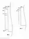
FIG. 3 is a front perspective view of one embodiment of a control unit 300 that houses the control system 200. As FIG. 3 illustrates, the control unit 300 includes a housing 305 having a shoulder 310 and an extension 315. The extension 315 includes an end surface 320, a first ridge 325, and a second ridge 330. The second ridge is generally located on the end surface 320 substantially opposite the first ridge 325. The general steps of the control unit 300 illustrated in FIG. 3 is an elliptic cylinder, but any geometric configuration that provides sufficient interior capacity for the control system 200 and the reduced pressure source 160 is acceptable. The extension 315 includes an aperture 335, through which the CAN port 236a is exposed to the exterior of the end surface 320.
FIG. 4 is an enlarged partial cross-section view of a control unit similar to the control unit 300 along line 4-4. In particular, FIG. 4 illustrates a partial housing 405 having a shoulder 410 and an extension 415. The extension 415 includes an end surface 420, a first ridge 425, and a second ridge 430 substantially opposite the first ridge 425. An aperture 435 extends from the exterior of the end surface 420 to the interior of the housing 405.
FIG. 5 is an enlarged partial cross-section view of a control unit similar to the control unit 300 along line 5-5. In particular, FIG. 5 illustrates a partial housing 505 having a shoulder 510 and an extension 515 with an end surface 520.
In any embodiment of the control unit, the housing may be manufactured as separate components and subsequently assembled, or may be manufactured as a single unit.
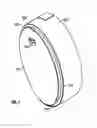
FIG. 6 is a perspective view of a first end of an embodiment of a component module 600. The component module 600 may include a variety of equipment that is useful for tissue treatment, including without limitation a wound camera, cyclic/next generation skin stretching, capacitive volume and wound contour mapping, wound bed pH monitoring, wound warming/climate control, wound moisture and temperature monitoring, electrical stimulation, UV therapy, and wound healing marker measurement. The component module 600 typically includes a control system similar to the control system 200 described above. In particular, the component module 600 includes a CAN controller (not shown) and a CAN port (see FIG. 7). The component module 600 also includes a CAN plug 610, which protrudes through an aperture 615 and interfaces with the CAN port 236a of the control system 200. As FIG. 6 illustrates, the component module 600 includes a housing 620 having a rim 625, a recessed end surface 630, and notches 632. The component module 600 further includes a mounting assembly 635 fixed to the recessed end surface 630. The mounting assembly 635 includes a first latch 640 and a second latch 645 that are positioned within the notches 632. The first latch and the second latch each have a fastener bar 650 that is substantially flush with the rim 625 in the configuration illustrated in FIG. 6. The fastener bars 650 are configured to overlap the ridges on other modules or on a control unit, such as ridges 425 and 430 illustrated in FIG. 4.
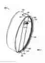
FIG. 7 is a perspective view of a second end of the component module 600 illustrated in FIG. 6. This perspective view illustrates a configuration that is substantially similar to the configuration of the control unit 300 described above with reference to FIGS. 3-5, so that additional component modules may be connected in a chain or series as needed to expand the functionality of a reduced pressure treatment system. In particular, the component module 600 includes the outer surface 620 having a shoulder 705, an extension 710 fixed to the shoulder, and an end surface 715. The extension 710 further includes a first ridge 720 and a second ridge 725, which is generally located opposite the first ridge 720, and an aperture 730, through which a CAN port may be exposed to the exterior of the end surface 715.
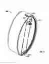
Referring to FIG. 8 for illustration, the first latch 630 and the second latch 635 may be extended to mount the component module 600 to a control unit or another component module. In alternate embodiments, the first latch 630, the second latch 635, or both may be rotated about a pin so that only the fastener bar of the latch is extended. Extending the mounting assembly 625 allows the fastener bars 650 to be placed over the ridges on another component module or control unit, and then collapsed onto the extension to secure the component module 600.
FIG. 9 illustrates the second end of the component module 600 shown in FIG. 7, with the first latch 630 extended.
FIG. 10 is an enlarged perspective view of an embodiment of a CAN plug 610. In this embodiment, the CAN plug 610 consists of a plurality of pin connectors that align with corresponding plate connectors in a CAN port. Each pin connector may be wired as desired to a control system within a component module.
It should be apparent from the foregoing that an invention having significant advantages has been provided. While the invention is shown in only a few of its forms, it is not so limited and is susceptible to various changes and modifications without departing from the spirit thereof.
Claims
We claim:1. A reduced pressure treatment component module comprising:
a substantially elliptic cylindrical housing having a rim, a recessed end surface, and an extension;
a mounting assembly fixed to the recessed end surface, the mounting assembly comprising an extendable first latch and an extendable second latch, wherein the first latch and the second latch each comprise a fastener bar that is substantially flush with the rim when the first latch and the second latch are not extended;
a control system contained within the housing, the control system having a communication controller.
2. The reduced pressure treatment component module according to claim 1, wherein the communication controller is a controller area network controller and the control system communicates using a controller area network (CAN) protocol.
3. The reduced pressure treatment component module according to claim 1, wherein the extension comprises a first ridge and a second ridge opposite the first ridge.
4. The reduced pressure treatment component module according to claim 1, wherein the second latch pivots about an axis to extend the fastener bar.
5. The reduced pressure treatment component module according to claim 1, wherein the component module is a wound camera.
6. The reduced pressure treatment component module according to claim 1, wherein the component module is a cyclic skin stretcher.
7. The reduced pressure treatment component module according to claim 1, wherein the component module is a capacitive volume and wound contour mapping module.
8. The reduced pressure treatment component module according to claim 1, wherein the component module is a wound bed pH monitor.
9. The reduced pressure treatment component module according to claim 1, wherein the component module is a wound climate control module.
10. The reduced pressure treatment component module according to claim 1, wherein the component module is a wound moisture and temperature monitor.
11. The reduced pressure treatment component module according to claim 1, wherein the component module is an electrical stimulation module.
12. The reduced pressure treatment component module according to claim 1, wherein the component module is an ultraviolet therapy module.
13. The reduced pressure treatment component module according to claim 1, wherein the component module is a wound healing marker measurement module.
14. A reduced pressure treatment system for treating a tissue site of a patient, the system comprising:
a control unit having a control system and a reduced pressure source;
a manifold unit in fluid communication with the reduced pressure source;
a component module to augment treatment and configured to communicate with the control system of the control unit, the component module having a first mounting region configured to be coupled to a complimentary mounting region of the control unit.
15. The reduced pressure treatment system of claim 14, wherein the component module is a first component module having a second mounting region identical to the complimentary mounting region of the control unit to allow a second component module to be coupled to the first component module, and further comprising:
one or more second component modules, the one or more second component modules having a third mounting region that is identical to the first mounting region of the first component module and a fourth mounting region that is identical to the second mounting region.
16. The reduced pressure treatment system of claim 14, wherein the first mounting region further comprises a rim and a recessed end surface.
17. The reduced pressure treatment system of claim 16, wherein the first mounting region further comprises a mounting assembly having a latch.
18. The reduced pressure treatment system of claim 14, wherein the complimentary mounting region of the control unit further comprises a shoulder and an extension surface.
19. The reduced pressure treatment system of claim 14, wherein:
the first mounting region further comprises a rim, a recessed end surface, and a latch;
the complimentary mounting region of the control unit further comprises a shoulder and an extension surface; and
the recessed end surface is configured to receive the extension surface, and the latch is configured to fasten to the extension surface to secure the component module to the control unit.
20. The reduced pressure treatment system of claim 19, wherein the extension surface includes a ridge and the latch includes a fastener bar that overlaps the ridge to secure the component module to the control unit.
Images & Drawings included:
Sources:
- United States Patent and Trademark Office - verify current appl. status at the USPTO↗
Similar patent applications:
- » 20080071216
Component module for a reduced pressure treatment system - » 20110106031
Component module for a reduced pressure treatment system - » 20140371696
Component module for a reduced pressure treatment system - » 20150245974
Component module for a reduced pressure treatment system - » 20160256616
Component module for a reduced pressure treatment system
Recent applications in this class:
- » 20250205412 2025-06-26
DISTRIBUTED NEGATIVE PRESSURE WOUND THERAPY SYSTEMS AND METHODS - » 20250135091 2025-05-01
SYSTEMS AND METHODS FOR USING NEGATIVE PRESSURE WOUND THERAPY TO MANAGE OPEN ABDOMINAL WOUNDS - » 20250121127 2025-04-17
ENDOLUMINAL TREATMENT DEVICES AND RELATED METHODS - » 20250121126 2025-04-17
ENDOLUMINAL TREATMENT SYSTEMS, DEVICES, AND RELATED METHODS - » 20250099670 2025-03-27
NASOGASTRIC TUBE - » 20250009956 2025-01-09
ENDOLUMINAL SEALING DEVICES AND RELATED METHODS OF USE - » 20240342359 2024-10-17
SURGICAL DRAINS AND SYSTEMS AND METHODS FOR USING SAME - » 20240342358 2024-10-17
SYSTEMS AND METHODS FOR APPLYING REDUCED PRESSURE THERAPY - » 20240335600 2024-10-10
Medicinal Applicator for Wound Care - » 20240307605 2024-09-19
COLLAPSIBLE SHEET FOR WOUND CLOSURE AND METHOD OF USE
Recent applications for this Assignee:
- » 20240033131 2024-02-01
FLUID INSTILLATION APPARATUS FOR USE WITH NEGATIVE-PRESSURE SYSTEM INCORPORATING WIRELESS THERAPY MONITORING - » 20230363953 2023-11-16
DRESSINGS FOR REDUCED TISSUE INGROWTH - » 20230330316 2023-10-19
System and apparatus for preventing therapy unit contamination - » 20230302269 2023-09-28
Apparatus for negative-pressure therapy and irrigation - » 20230093695 2023-03-23
System and method for improving battery life of portable negative-pressure therapy through hysteresis control - » 20230090100 2023-03-23
Negative-pressure wound therapy dressing with zone of ambient pressure - » 20220379003 2022-12-01
DRESSING WITH AREA MANAGEMENT FOR EXTREMITIES - » 20220362062 2022-11-17
Systems, apparatuses, and methods for negative-pressure treatment with reduced tissue in-growth and extended wear time - » 20220313493 2022-10-06
Wound dressing construct with high wicking adhesive border - » 20220296770 2022-09-22
Dressing with epithelialization and scar reduction feature