Power conversion controller having a novel power factor correction mechanism using line voltage normalization
US20120126759A1
2012-05-24
12/953,219
2010-11-23
✅ Patent granted
US 8,541,990 B2
2013-09-24
-
-
Bao Q Vu | Zekre Tsehaye
Ming Chow | Sinorica, LLC
2031-10-15
Abstract:
A power conversion controller having a novel power factor correction mechanism, including: a normalization unit, used to generate a normalized signal according to a line voltage by multiplying the line voltage with a normalizing gain, wherein the normalizing gain is proportional to the reciprocal of the amplitude of the line voltage; a reference current generation unit, coupled to the normalization unit to generate a reference current signal by performing an arithmetic operation, wherein the arithmetic operation involves the normalized signal; and a gate drive signal generation unit, used to generate a gate drive signal, wherein the duty of the gate drive signal is determined by a voltage comparison of the reference current signal and a current sensing signal.
Inventors:
- Wei Chuan Su 13 🇹🇼 Taipei, Taiwan
- Chia-Chieh HUNG 5 🇹🇼 Taipei, Taiwan
- Ko-Yen LEE 4 🇹🇼 Taipei, Taiwan
Assignee:
- IMMENSE ADVANCE TECHNOLOGY CORP. 8 🇹🇼 Taipei, Taiwan
Applicant:
Interested in similar patents?
Get notified when new applications in this technology area are published.
Classification:
H02M1/4225 » CPC main
Details of apparatus for conversion; Circuits or arrangements for compensating for or adjusting power factor in converters or inverters; Arrangements for improving power factor of AC input using a non-isolated boost converter
H05B45/3725 » CPC further
Circuit arrangements for operating light emitting diodes [LEDs]; Driver circuits; Converter circuits Switched mode power supply [SMPS]
H05B45/375 » CPC further
Circuit arrangements for operating light emitting diodes [LEDs]; Driver circuits; Converter circuits; Switched mode power supply [SMPS] using buck topology
H05B45/38 » CPC further
Circuit arrangements for operating light emitting diodes [LEDs]; Driver circuits; Converter circuits; Switched mode power supply [SMPS] using boost topology
H05B45/385 » CPC further
Circuit arrangements for operating light emitting diodes [LEDs]; Driver circuits; Converter circuits; Switched mode power supply [SMPS] using flyback topology
Y02B70/10 » CPC further
Technologies for an efficient end-user side electric power management and consumption Technologies improving the efficiency by using switched-mode power supplies [SMPS], i.e. efficient power electronics conversion e.g. power factor correction or reduction of losses in power supplies or efficient standby modes
G05F1/70 IPC
Automatic systems in which deviations of an electric quantity from one or more predetermined values are detected at the output of the system and fed back to a device within the system to restore the detected quantity to its predetermined value or values, i.e. retroactive systems Regulating power factor; Regulating reactive current or power
G05F5/00 IPC
Systems for regulating electric variables by detecting deviations in the electric input to the system and thereby controlling a device within the system to obtain a regulated output
Description
BACKGROUND OF THE INVENTION
1. Field of the Invention
The present invention relates to a power conversion controller, and more particularly to a power conversion controller capable of providing power factor correction for power conversion applications requiring load current regulation.
2. Description of the Related Art
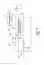
FIG. 1 illustrates a power conversion application, in which a prior art controller 100 having a power factor correction mechanism is used to control a power conversion circuit 110 such that the waveform of an input current IIN of the power conversion circuit 110 is analog to that of a line voltage VLINE, and the average of the input current IIN is regulated to result in a DC output voltage VO for a load 120. As can be seen in FIG. 1, the controller includes a combiner 101, an amplifier 102, a multiplier 103, and a gate drive signal generation unit 104.
The combiner 101 is used to generate an error signal by subtracting VO with a reference voltage VREF. The amplifier 102, having a high DC gain and a cutoff frequency below 120 HZ, is used to amplify the error signal with a negative gain to generate an amplitude adjusting signal A.
The multiplier 103 is used to multiply the line voltage VLINE with the amplitude adjusting signal A to generate a reference current signal SREFC.
The gate drive signal generation unit 104 is used to generate a gate drive signal VG to control the switching of the power conversion circuit 110, wherein the duty of the gate drive signal VG is determined according to a voltage comparison of the reference current signal SREFC and a current sensing signal SCS, which represents the input current IIN.
When in operation, the current sensing signal SCS will follow the reference current signal SREFC, and the negative feedback mechanism will force VO to approach VREF. As such, if the line voltage VLINE is changed to a higher/lower level, the amplitude of the reference current signal SREFC will be adjusted by the amplitude adjusting signal A to a smaller/larger value to result in a lower/higher level of the current sensing signal SCS so as to regulate VO at VREF. That is, the reference current signal SREFC, of which the waveform is analog to that of the line voltage VLINE, and of which the amplitude is equal to the product of the amplitude adjusting signal A and the amplitude of the line voltage VLINE, is the key signal for achieving power factor correction and output voltage regulation at the same time.
However, there is a major disadvantage in this architecture—the amplifier 102 occupies a large area due to the required high gain and low cut-off frequency.
In view of this problem, the present invention proposes a power conversion controller having a novel power factor correction mechanism for power conversion applications.
SUMMARY OF THE INVENTION
The major objective of the present invention is to propose a power conversion controller having a novel power factor correction mechanism for a power conversion circuit, which can be of buck type, buck-boost type, or boost type etc.
To achieve the foregoing objective of the present invention, a power conversion controller having a novel power factor correction mechanism is proposed, the power conversion controller including:
a normalization unit, used to generate a normalized signal according to a line voltage by multiplying the line voltage with a normalizing gain, wherein the normalizing gain is proportional to the reciprocal of the amplitude of the line voltage;
a reference current generation unit, coupled to the normalization unit to generate a reference current signal by performing an arithmetic operation, wherein the arithmetic operation involves the normalized signal; and
a gate drive signal generation unit, used to generate a gate drive signal, wherein the duty of the gate drive signal is determined by a voltage comparison of the reference current signal and a current sensing signal.
To make it easier for our examiner to understand the objective of the invention, its structure, innovative features, and performance, we use preferred embodiments together with the accompanying drawings for the detailed description of the invention.
BRIEF DESCRIPTION OF THE DRAWINGS
FIG. 1 illustrates a power conversion application, in which a prior art controller having a power factor correction mechanism is used to control a power conversion circuit such that the waveform of an input current is analog to that of a line voltage, and the average of the input current is regulated to result in a DC output voltage for a load.
FIG. 2 illustrates a power conversion application, in which a controller having a novel power factor correction mechanism according to a preferred embodiment of the present invention is used to control a power conversion circuit, such that the waveform of an input current is analog to a line voltage, and the average of the output current is regulated according to a constant level.
FIG. 3 illustrates the block diagram of a reference current signal generation module in FIG. 2 according to a preferred embodiment of the present invention.
FIG. 4 illustrates the block diagram of a reference current signal generation module in FIG. 2 according to another preferred embodiment of the present invention.
FIG. 5 illustrates the block diagram of a reference current signal generation module in FIG. 2 according to still another preferred embodiment of the present invention.
FIG. 6 illustrates the block diagram of a reference current signal generation module in FIG. 2 according to still another preferred embodiment of the present invention.
FIG. 7 illustrates the block diagram of a reference current signal generation module in FIG. 2 according to still another preferred embodiment of the present invention.
DETAILED DESCRIPTION OF THE PREFERRED EMBODIMENTS
The present invention will be described in more detail hereinafter with reference to the accompanying drawings that show the preferred embodiment of the invention.
Please refer to FIG. 2, which illustrates a power conversion application, in which a controller 200 having a novel power factor correction mechanism according to a preferred embodiment of the present invention is used to control a power conversion circuit 230, such that the waveform of an input current IIN is analog to a line voltage VLINE, and the average of the output current IO is regulated according to a constant level to supply a load 240 with a corresponding output voltage VO. As can be seen in FIG. 2, the controller 200 includes a reference current signal generation module 210—having a normalization unit 211 and a reference current generation unit 212—and a gate drive signal generation unit 220.
The normalization unit 211 is used to generate a normalized signal VNORM according to the line voltage VLINE by multiplying the line voltage VLINE with a normalizing gain SG, wherein the normalizing gain SG is proportional to the reciprocal of the amplitude of the line voltage VLINE. The normalization unit 211 can utilize, for example but not limited to, an auto gain control mechanism to implement the equation: VNORM=VLINE×SG, wherein SG is derived through an adjusting process such that the amplitude of VNORM is constant irrespective of different amplitudes of VLINE.
The reference current generation unit 212 is coupled to the normalization unit 211 to generate a reference current signal SREFC by performing an arithmetic operation, wherein the arithmetic operation, which involves the normalized signal VNORM, can be one selected from the group consisting of SREFC=VNORM×SG, SREFC=VNORM, SREFC=VNORM×VNORM, SREFC=VNORM×(VNORM+VO×SG), and SREFC=VNORM×(VO×SG).
The gate drive signal generation unit 220 is used to generate a gate drive signal VG, wherein the duty of the gate drive signal VG is determined by a voltage comparison of the reference current signal SREFC and a current sensing signal SCS.
For different types of power converter in different operation modes, different forms of the arithmetic operation involving the normalized signal VNORM can be used, and, during the voltage comparison process, the reference current signal SREFC can be used as a peak reference current to determine the peak value of the current sensing signal SCS, or used as an average reference current to determine the average value of the current sensing signal SCS.
For example, if the power conversion application is a boundary current mode boost convertor, then the reference current signal generation module 210 can be implemented with the circuit block illustrated in FIG. 3, which includes a normalization unit 211 and a multiplier 312 to realize the equation SREFC=VNORM×SG. The reference current signal SREFC so designed can render a constant average output current and an excellent power factor in the meantime for this type of application. The principle is elaborated as follows:
With VLINE expressed as VA sin θ, 0°<θ<180° for a cycle of the full-wave rectified line voltage VLINE, and the switching frequency of VG is much higher than that of VLINE, by employing SREFC=VNORM×SG as a peak reference current, during one switching cycle, the input power can be expressed as VLINE×IIN,avg=VLINE×SREFC/2=VLINE×VNORM×SG/2=VNORM×VNORM/2=(K sin θ)2/2, wherein IIN,avg represents the average of the input current IIN, SG=K/VA, and K is a constant; and the average output current IO,avg can be expressed as IO,avg=(SREFC/2)×tOFF/(tON+tOFF)=(SREFC/2)×VLINE/VO=(VNORM×SG/2)×VLINE/VO=(VNORM)2/2VG=(K sin θ)2/2VO, wherein tON is the active period of VG and tOFF is the inactive period of VG. As such, the input current IIN is in phase with the line voltage VLINE, and the average output current over the cycle of the full-wave rectified line voltage VLINE is independent of the amplitude of VLINE.
Further, if the power conversion application is a discontinuous current mode fixed frequency flyback convertor, then the reference current signal generation module 210 can be implemented with the circuit block illustrated in FIG. 4, which includes a normalization unit 211 and a buffer 412 to realize the equation SREFC=VNORM. The reference current signal SREFC so designed can render a constant average output current and an excellent power factor in the meantime for this type of application. The principle is elaborated as follows:
With VLINE expressed as VA sin θ, 0°<θ<180° for a cycle of the full-wave rectified line voltage VLINE, and the switching frequency of VG is much higher than that of VLINE, by employing SREFC=VNORM as a peak reference current, during one switching cycle, the input power can be expressed as VLINE×IIN,avg=L(SREFC)2/2T=L(VNORM)2/2T=L(K sin θ)2/2T, wherein IIN,avg represents the average of the input current IIN, L is the inductance of an inductor, K is a constant and T is the switching cycle period; and the average output current IO,avg can be expressed as IO,avg=PIN/VO=L(K sin θ)2/2TVO, wherein PIN is the input power. As such, the input current is in phase with the line voltage VLINE, and the average output current over the cycle of the full-wave rectified line voltage VLINE is independent of the amplitude of VLINE. It is to be noted that the buffer 412 can be replaced with another equivalent circuit—a feedthrough connection for example.
Still further, if the power conversion application is a buck convertor or a forward convertor considered as a primary side equivalent circuit, then the reference current signal generation module 210 can be implemented with the circuit block illustrated in FIG. 5, which includes a normalization unit 211 and a multiplier 512 to realize the equation SREFC=VNORM×VNORM. The reference current signal SREFC so designed can render a constant average output current and an excellent power factor in the meantime for this type of application, and what is more, since the average output current will be independent of the output voltage, the design is especially suitable for a LED lighting application, of which the output voltage can vary a lot due to the spec variation of LEDs. The principle is elaborated as follows:
With VLINE expressed as VA sin θ, 0°<θ<180° for a cycle of the full-wave rectified line voltage VLINE, and the switching frequency of VG is much higher than that of VLINE, by employing SREFC=VNORM×VNORM as a peak reference current for boundary current mode operation, during one switching cycle, the input power can be expressed as VLINE×IIN,avg=VLINE×((SREFC/2)×tOFF/(ION+tOFF))=VLINE×((SREFC/2)×VO/VLINE)=(VNORM)2×VO/2=VO(K sin θ)2/2, wherein IIN,avg represents the average of the input current IIN, tON is the active period of VG, tOFF is the inactive period of VG, and K is a constant; and the average output current IO,avg can be expressed as IO,avg=SREFC/2=(VNORM)2/2=(K sin θ)2/2.
As for continuous current mode, by employing SREFC=VNORM×VNORM as an average reference current, during one switching cycle, the input power can be expressed as VLINE×IIN,avg=VLINE×(SREFC×VO/VLINE)=(VNORM)2×VO=VO(K sin θ)2, wherein IIN,avg represents the average of the input current IIN, and K is a constant; and the average output current IO,avg can be expressed as IO,avg=SREFC=(VNORM)2=(K sin θ)2. As such, the input current is in phase with the line voltage VLINE, and the average output current over the cycle of the full-wave rectified line voltage VLINE is independent of the amplitude of VLINE and VO.
Still further, if the power conversion application is a buck-boost convertor or a flyback convertor considered as a primary side equivalent circuit, then the reference current signal generation module 210 can be implemented with the circuit block illustrated in FIG. 6, which includes a normalization unit 211, a variable gain amplifier 612a, a combiner 612b, and a multiplier 612c to realize the equation SREFC=VNORM×(VNORM+VO×SG). The reference current signal SREFC so designed can render a constant average output current and an excellent power factor in the meantime for this type of application, and what is more, since the average output current will be independent of the output voltage, the design is especially suitable for a LED lighting application, of which the output voltage can vary a lot due to the spec variation of LEDs. The principle is elaborated as follows:
With VLINE expressed as VA sin θ, 0°<θ<180° for a cycle of the full-wave rectified line voltage VLINE, and the switching frequency of VG is much higher than that of VLINE, by employing SREFC=VNORM×(VNORM+VO×SG) as a peak reference current for boundary current mode operation, during one switching cycle, the input power can be expressed as VLINE×IIN,avg=VLINE×((SREFC/2)×VO/(VLINE+VO))=(VNORM)2/2×VO=VO(K sin θ)2/2, wherein IIN,avg represents the average of the input current IIN, and K is a constant; and the average output current IO,avg can be expressed as IO,avg=(SREFC/2)×tOFF/(tON+tOFF))=(SREFC/2)×VLINE/(VO+VLINE)=VNORM×(VNORM+VO×SG)×VLINE/(VO+VLINE)/2=(VNORM)22=(K sin θ)2/2, wherein tON is the active period of VG and tOFF is the inactive period of VG.
As for continuous current mode, by employing SREFC=VNORM×(VNORM+VG×SG) as an average reference current, during one switching cycle, the input power can be expressed as VLINE×IIN,avg=VLINE×(SREFC×VO/(VLINE+VO))=(VNORM)2×VO=VO(K sin θ)2, wherein IIN,avg represents the average of the input current IIN, and K is a constant; and the average output current IO,avg can be expressed as IO,avg=SREFC×tOFF/(tON+tOFF))=SREFC×VLINE/(VO+VLINE)=VNORM×(VNORM+VO×SG)×VLINE/(VO+VLINE)=(VNORM)2=(K sin θ)2, wherein tON is the active period of VG and tOFF is the inactive period of VG. As such, the input current is in phase with the line voltage VLINE, and the average output current over the cycle of the full-wave rectified line voltage VLINE is independent of the amplitude of VLINE and VO.
Still further, if the power conversion application is a boost convertor, then the reference current signal generation module 210 can be implemented with the circuit block illustrated in FIG. 7, which includes a normalization unit 211, a variable gain amplifier 712a, and a multiplier 712c to realize the equation SREFC=VNORM×(VO×SG). The reference current signal SREFC so designed can render a constant average output current and an excellent power factor in the meantime for this type of application, and what is more, since the average output current will be independent of the output voltage, the design is especially suitable for a LED lighting application, of which the output voltage can vary a lot due to the spec variation of LEDs. The principle is elaborated as follows:
With VLINE expressed as VA sin θ, 0°<θ<180° for a cycle of the full-wave rectified line voltage VLINE, and the switching frequency of VG is much higher than that of VLINE, by employing SREFC=VNORM×(VO×SG) as a peak reference current for boundary current mode operation, during one switching cycle, the input power can be expressed as VLINE×IIN,avg=VLINE×SREFC=VLINE×VNORM×(VO×SG)=(VNORM)2×VO=VO(K sin θ)2, wherein IIN,avg represents the average of the input current IIN, and K is a constant; and the average output current IO,avg can be expressed as IO,avg=(SREFC/2)×tOFF/(tON+tOFF)=(SREFC/2)×VLINE/VO=VNORM×(VO×SG)×VLINE/VO/2=(VNORM)2/2=(K sin θ)2/2, wherein tON is the active period of VG and tOFF is the inactive period of VG.
As for continuous current mode, by employing SREFC=VNORM×(VO×SG) as an average reference current, during one switching cycle, the input power can be expressed as VLINE×IIN,avg=VLINE×SREFC=VLINE×VNORM×(VO×SG)=(VNORM)2×VO=VO(K sin θ)2, wherein IIN,avg represents the average of the input current IIN, and K is a constant; and the average output current IO,avg can be expressed as IO,avg=SREFC×tOFF/(tON+tOFF)=SREFC×VLINE/VO=VNORM×(VO×SG)×VLINE/VO=(VNORM)2=(K sin θ)2, wherein tON is the active period of VG and tOFF is the inactive period of VG. As such, the input current is in phase with the line voltage VLINE, and the average output current over the cycle of the full-wave rectified line voltage VLINE is independent of the amplitude of VLINE and VO.
As can be seen from the specification above, by using the power conversion controller of the present invention having a normalization unit for processing a line voltage, a novel power factor correction mechanism for power converters of buck type, buck-boost type, boost type, fly-back type, etc. is proposed, and the large error amplifier needed in prior art is eliminated. Therefore, the present invention does improve the prior art controllers and is worthy of being granted a patent.
While the invention has been described by way of example and in terms of a preferred embodiment, it is to be understood that the invention is not limited thereto. To the contrary, it is intended to cover various modifications and similar arrangements and procedures, and the scope of the appended claims therefore should be accorded the broadest interpretation so as to encompass all such modifications and similar arrangements and procedures.
In summation of the above description, the present invention herein enhances the performance than the conventional structure and further complies with the patent application requirements and is submitted to the Patent and Trademark Office for review and granting of the commensurate patent rights.
Claims
What is claimed is:1. A power conversion controller having a novel power factor correction mechanism, comprising:
a normalization unit, using an auto gain control mechanism to generate a normalized signal and a normalizing gain according to a line voltage, wherein said normalized signal is equal to the product of said line voltage and said normalizing gain, and said normalizing gain is proportional to the reciprocal of the amplitude of said line voltage;
a reference current generation unit, coupled to said normalization unit to generate a reference current signal by performing an arithmetic operation, wherein said arithmetic operation involves said normalized signal; and
a gate drive signal generation unit, used to generate a gate drive signal, wherein the duty of said gate drive signal is determined by a voltage comparison of said reference current signal and a current sensing signal.
2. The power conversion controller having a novel power factor correction mechanism as claim 1, wherein said reference current generation unit comprises a multiplier to implement said arithmetic operation as: SREFC=VNORM×SG, wherein SREFC represents said reference current signal, VNORM represents said normalized signal, and SG represents said normalizing gain.
3. The power conversion controller having a novel power factor correction mechanism as claim 1, wherein said reference current generation unit comprises a buffer to implement said arithmetic operation as: SREFC=VNORM, wherein SREFC represents said reference current signal, and VNORM represents said normalized signal.
4. The power conversion controller having a novel power factor correction mechanism as claim 1, wherein said reference current generation unit comprises a multiplier to implement said arithmetic operation as: SREFC=VNORM×VNORM, wherein SREFC represents said reference current signal, and VNORM represents said normalized signal.
5. The power conversion controller having a novel power factor correction mechanism as claim 1, wherein said reference current generation unit comprises a variable gain amplifier, a combiner, and a multiplier to implement said arithmetic operation as: SREFC=VNORM×(VNORM+VO×SG), wherein SREFC represents said reference current signal, VNORM represents said normalized signal, VO represents an output voltage, and SG represents said normalizing gain.
6. The power conversion controller having a novel power factor correction mechanism as claim 1, wherein said reference current generation unit comprises a variable gain amplifier, and a multiplier to implement said arithmetic operation as: SREFC=VNORM×(VO×SG), wherein SREFC represents said reference current signal, VNORM represents said normalized signal, VO represents an output voltage, and SG represents said normalizing gain.
7. A power conversion controller having a novel power factor correction mechanism, comprising:
a normalization unit, used to generate a normalized signal according to a line voltage by multiplying said line voltage with a normalizing gain, wherein said normalizing gain is proportional to the reciprocal of the amplitude of said line voltage;
a reference current generation unit, coupled to said normalization unit to generate a reference current signal by performing an arithmetic operation, wherein said arithmetic operation involves said normalized signal; and
a gate drive signal generation unit, used to generate a gate drive signal, wherein the duty of said gate drive signal is determined by a voltage comparison of said reference current signal and a current sensing signal.
8. The power conversion controller having a novel power factor correction mechanism as claim 7, wherein said reference current generation unit is used to implement said arithmetic operation according to one selected from the group consisting of SREFC=VNORM×SG, SREFC=VNORM, SREFC=VNORM×VNORM, SREFC=VNORM×(VNORM+VO×SG), and SREFC=VNORM×(VO×SG), wherein SREFC represents said reference current signal, VNORM represents said normalized signal, VO represents an output voltage, and SG represents said normalizing gain.
9. The power conversion controller having a novel power factor correction mechanism as claim 8, wherein said reference current signal is used as a peak reference current in said gate drive signal generation unit.
10. The power conversion controller having a novel power factor correction mechanism as claim 8, wherein said reference current signal is used as an average reference current in said gate drive signal generation unit.
Images & Drawings included:


Sources:
- United States Patent and Trademark Office - verify current appl. status at the USPTO↗
Recent applications in this class:
- » 20250260313 2025-08-14
SYSTEM AND METHODS FOR USING A MEMS SWITCH AS AN IDEAL DIODE - » 20250219530 2025-07-03
MULTI-INPUT POWER SYSTEM - » 20250202347 2025-06-19
CONDUCTION MODE SWITCHING FOR SWITCHING MODE POWER SUPPLY - » 20250167672 2025-05-22
NONLINEAR, DISCRETE TIME CONTROL OF POWER FACTOR CORRECTION POWER CONVERTER - » 20250167671 2025-05-22
THREE-PHASE MULTI-LEVEL BOOST PFC RECTIFIER WITH FLYING CAPACITORS - » 20250119056 2025-04-10
POWER SUPPLY CONTROL CIRCUIT, RELATED POWER SUPPLY AND METHOD OF OPERATING A POWER SUPPLY - » 20250055367 2025-02-13
POWER CONVERSION APPARATUS, CONTROL APPARATUS, AND SWITCH-MODE POWER SUPPLY - » 20250047198 2025-02-06
INTEGRATED CIRCUIT AND POWER SUPPLY CIRCUIT - » 20250047197 2025-02-06
CHARGER, CONTROL METHOD, AND RECORDING MEDIUM - » 20250038653 2025-01-30
POWER DELIVERY FAST CHARGING CONTROL CIRCUIT AND POWER DELIVERY FAST CHARGING CONTROL METHOD
Recent applications for this Assignee:
- » 20120306404 2012-12-06
LED DRIVER CIRCUIT - » 20120182001 2012-07-19
LOW INPUT VOLTAGE BOOST CONVERTER OPERABLE AT LOW TEMPERATURES AND BOOST CONTROLLER THEREOF - » 20120062194 2012-03-15
High side controller capable of sensing input voltage and ouput voltage of a power conversion circuit - » 20120043908 2012-02-23
LED driver controller - » 20120032614 2012-02-09
LED driver circuit - » 20110298390 2011-12-08
Power conversion controller having an adaptive peak current reference - » 20110285678 2011-11-24
LED driver circuit having a bias current drawn from a load current