Prestressing device having circumferential activity
US20120128490A1
2012-05-24
13/388,461
2010-07-23
✅ Patent granted
US 9,145,942 B2
2015-09-29
WO; PCT/EP2010/060741; 20100723
WO; WO2011/015474; 20110210
Nathaniel Wiehe | Woody A Lee, Jr.
Oblon, McClelland, Maier & Neustadt, L.L.P.
2032-09-18
Abstract:
A prestressing device extending about an axis between a first plane and a second plane, the first plane being located at a predetermined distance from the second plane, each plane being perpendicular to the axis. The device includes at least three deformation areas. The deformation areas extend in the first plane. The device further includes, between each deformation area, a planar contact surface extending in the second plane.
Inventors:
- Eric Jacques Boston 9 🇫🇷 Cesson, France
- Michel Andre Bouru 29 🇫🇷 Montereau Sur Le Jard, France
- Laurent Jablonski 17 🇫🇷 Melun, France
- Philippe Gerard, Edmond Joly 12 🇫🇷 Vaux le Penil, France
Assignee:
- SNECMA 2,018 🇫🇷 Paris, France
Applicant:
Interested in similar patents?
Get notified when new applications in this technology area are published.
Classification:
F02C6/206 » CPC further
Plural gas-turbine plants; Combinations of gas-turbine plants with other apparatus ; Adaptations of gas- turbine plants for special use; Adaptations of gas-turbine plants for driving vehicles the vehicles being airscrew driven
B64D2027/005 » CPC further
Arrangement or mounting of power plant in aircraft; Aircraft characterised thereby Aircraft with an unducted turbofan comprising contra-rotating rotors, e.g. contra-rotating open rotors [CROR]
F05D2220/36 » CPC further
Application in turbines specially adapted for the fan of turbofan engines
F05D2250/182 » CPC further
Geometry; Two-dimensional patterned crenellated, notched
F05D2250/184 » CPC further
Geometry; Two-dimensional patterned sinusoidal
F05D2300/501 » CPC further
Materials; Properties thereof; Intrinsic material properties or characteristics Elasticity
F16C2360/00 » CPC further
Engines or pumps
Y02T50/60 » CPC further
Aeronautics or air transport Efficient propulsion technologies, e.g. for aircraft
Y02T50/60 » CPC further
Aeronautics or air transport Efficient propulsion technologies, e.g. for aircraft
F16F1/18 IPC
Springs made of steel or other material having low internal friction ; Wound, torsion, leaf, cup, ring or the like springs, the material of the spring not being relevant Leaf springs
F16B43/02 IPC
Washers or equivalent devices; Other devices for supporting bolt-heads or nuts with special provisions for engaging surfaces which are not perpendicular to a bolt axis or do not surround the bolt
F16F1/34 IPC
Springs made of steel or other material having low internal friction ; Wound, torsion, leaf, cup, ring or the like springs, the material of the spring not being relevant Ring springs, i.e. annular bodies deformed radially due to axial load
F16F1/328 » CPC main
Springs made of steel or other material having low internal friction ; Wound, torsion, leaf, cup, ring or the like springs, the material of the spring not being relevant; Belleville-type springs with undulations, e.g. wavy springs
F16C25/083 » CPC further
Bearings for exclusively rotary movement adjustable for wear or play; Ball or roller bearings self-adjusting with resilient means acting axially on a race ring to preload the bearing
F16F1/027 » CPC further
Springs made of steel or other material having low internal friction ; Wound, torsion, leaf, cup, ring or the like springs, the material of the spring not being relevant characterised by having a particular shape Planar, e.g. in sheet form; leaf springs
F01D25/164 » CPC further
Component parts, details, or accessories, not provided for in, or of interest apart from, other groups; Arrangement of bearings; Supporting or mounting bearings in casings; Bearing supports Flexible supports; Vibration damping means associated with the bearing
F16B39/24 IPC
Locking of screws, bolts or nuts in which the locking takes place during screwing down or tightening by means of washers, spring washers, or resilient plates that lock against the object
F16F1/32 IPC
Springs made of steel or other material having low internal friction ; Wound, torsion, leaf, cup, ring or the like springs, the material of the spring not being relevant Belleville-type springs
F16F1/02 IPC
Springs made of steel or other material having low internal friction ; Wound, torsion, leaf, cup, ring or the like springs, the material of the spring not being relevant
F16C25/08 IPC
Bearings for exclusively rotary movement adjustable for wear or play; Ball or roller bearings self-adjusting
F01D25/16 IPC
Component parts, details, or accessories, not provided for in, or of interest apart from, other groups Arrangement of bearings; Supporting or mounting bearings in casings
Description
The present invention relates to a prestressing device intended to ensure contact between rolling elements and their rolling track.
It applies in particular to an impeller rotor, with no fairing, for a turbine engine. In these devices, a nut is provided for pressing one of the bearings against the rim of a collar. A locking washer is then provided between the bearing and the nut so as to fix this nut in rotation within the housing of the polygonal ring.
A prestressing device is then advantageously provided in order to permanently generate a stress between the pieces. Known prestressing devices include star-shaped springs known as Ringspann washers. Also known are washers with a shape similar to that of Belleville washers. These washers are conical so as to function as a spring and thus permanently stress the pieces in question.
It has been noted that there is a problem of the pieces wearing when the known prestressing devices are used and in particular in the context of mechanical assemblies which are subject to high vibration levels such as, for example, turbine engines.
The object of the invention is in particular to provide a solution to this problem.
The subject of the invention is a prestressing device making it possible to reduce the wear of pieces which must be subjected to prestress in all types of assembly.
To this end it proposes a prestressing device which extends about an axis between a first plane substantially perpendicular to the axis and a second plane substantially parallel to the first plane and axially offset with respect to the latter, the device comprising at least three deformation zones, characterized in that the deformation zones extend within the first plane, and in that the device comprises, between each deformation zone, a planar contact surface extending within the second plane.
According to the invention, the device is thus no longer conical but comprises two parts which each extend within a plane perpendicular to its axis. The deformation zone extends within the second plane. It will ensure surface contact with a first piece, in particular a locking washer or a nut. The planar contact surfaces extend within the second plane and hence ensure surface contact with a second piece, in particular one of the bearings of the turbine engine. By virtue of these contact surfaces, the prestressing force is better distributed and a significant decrease is thus obtained in the wear resulting from the contact between the pieces which must be subjected to prestress. The lifetime of the pieces in question is thus increased.
The device preferably comprises inclined transition zones between each deformation zone and the contact surfaces adjacent to the deformation zone. Each inclined transition zone advantageously comprises a first rounded end part connected to one of the deformation zones, a second end part connected to one of the planar contact surfaces and an essentially planar central part between the first and second end parts. This makes it possible to considerably limit the stress concentration.
Each deformation zone can comprise a first recess extending radially inward and a second recess extending radially outward. It has been noted that such a shape ensures an effective deformation when the device is fitted between the pieces which are to be permanently stressed.
For each of the contact surfaces, two successive planar contact surfaces are advantageously separated from each other by a predetermined distance. This makes it possible to better distribute the prestressing force over the circumference of the pieces which are to be stressed.
The number of planar contact surfaces is preferably chosen to be between ten and twenty, and more particularly between thirteen and seventeen. It has been noted that the distribution of the prestressing force is optimized by the selection of these values.
The present invention also relates to a rotor, in particular an impeller rotor, with no fairing, for a turbine engine, comprising a prestressing device as described above.
The invention will be better understood and other details, features and advantages of the present invention will become more apparent on reading the following description, made by way of non-limiting example and with reference to the attached drawings, in which:
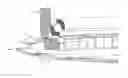
FIG. 1 is a partial perspective schematic view of a prestressing device, according to the invention, on a nut,
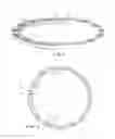
FIG. 2 is a schematic view from above of the prestressing device according to FIG. 1, and
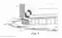
FIG. 3 is a partial perspective schematic view of the device in FIG. 1 placed between the nut and the locking washer, on the one hand, and the bearing, on the other hand.
Reference is made first to FIG. 1 which shows a prestressing device 10 consisting of an annular element.
This device consists of a succession of deformation zones 11, transition zones 13 and planar contact surfaces 12.
The deformation zones 11 extend within a first plane perpendicular to the axis A of the device. Each deformation zone comprises in particular recesses 14 and 15. As illustrated in FIG. 1, a first recess 14 extends inward, in other words toward the axis A of the device. The second recess 15 extends radially outward.
The transition zones 13 each have rounded end parts 16 and 17 and an essentially planar central part 18.
The planar contact surfaces 12 extend within a second plane parallel to the first plane. The distance between the first plane and the second plane is determined as a function of the desired travel of the device.
The prestressing device 10 (FIG. 2) comprises, in the example shown, a series of fifteen contact surfaces 12. Between ten and twenty contact surfaces are generally provided, preferably between thirteen and seventeen contact surfaces.
Two successive planar contact surfaces are separated from each other by a predetermined distance (D) which is preferably the same for each successive series of two planar contact surfaces so as to distribute the forces homogeneously.
When the prestressing device is fitted as shown in FIG. 3, it can be seen that the device 10 is placed between the unit formed by a nut 21 and its locking washer 22, on the one hand, and a bearing 23 (a ball bearing in the example shown), on the other hand. The bearing 23 is housed in a polygonal ring 24. The lower surfaces of the deformation zones 11 are in contact with the upper surface of the locking washer 22. The planar contact surfaces 12 are in contact with the lower surface of the bearing 23. Genuine surface contact between the different pieces is thus ensured.
In an alternative embodiment (not shown), the number of tabs per element can be less than 10.
The prestressing device according to the invention has been shown fitted in a rotor assembly, which may be an impeller rotor, with no fairing, for a turbine engine. It may, however, be used in other assemblies where a permanent stress is required. The device is particularly advantageous in mechanical units which are subjected to high vibration levels such as, for example, turbine engines.
Claims
1-7. (canceled)
8. A prestressing device which extends about an axis between a first plane substantially perpendicular to the axis and a second plane substantially parallel to the first plane and axially offset with respect to the first plane, the device comprising:
at least three deformation zones, wherein the deformation zones extend within the first plane; and
between each deformation zone, a planar contact surface extending within the second plane.
9. The device as claimed in claim 8, further comprising inclined transition zones between each deformation zone and the contact surfaces adjacent to the deformation zone.
10. The device as claimed in claim 9, wherein each inclined transition zone comprises a first rounded end part connected to one of the deformation zones, a second end part connected to one of the planar contact surfaces, and an essentially planar central part between the first and second end parts.
11. The device as claimed in claim 8, wherein each deformation zone comprises a first recess extending radially inward and a second recess extending radially outward.
12. The device as claimed in claim 8, wherein, for each of the contact surfaces, two successive planar contact surfaces are separated from each other by a predetermined distance.
13. The device as claimed in claim 8, further comprising a number of planar contact surfaces tabs between ten and twenty, or between thirteen and seventeen.
14. A rotor, or an impeller rotor, with no fairing, for a turbine engine, comprising a prestressing device as claimed in claim 8.
Images & Drawings included:
Sources:
- United States Patent and Trademark Office - verify current appl. status at the USPTO↗
Recent applications in this class:
- » 20250172184 2025-05-29
NESTED CREST-TO-CREST WAVE SPRING - » 20220381311 2022-12-01
WAVE COIL SPRING AND METHOD FOR ADDITIVELY MANUFACTURING THEREOF - » 20210207675 2021-07-08
Wave spring body including fingers - » 20210003185 2021-01-07
Wave spring - » 20200325951 2020-10-15
Deformable body and method for the production thereof - » 20200011392 2020-01-09
WAVE SPRING - » 20190390728 2019-12-26
Disk spring for a variable turbine geometry of an exhaust gas turbocharger - » 20150362036 2015-12-17
Gap-type, single turn, tooled wave spring - » 20150176670 2015-06-25
WAVE SPRING HAVING A LINEAR CHARACTERISTIC IN SOME REGIONS - » 20150042025 2015-02-12
Wave spring and load adjusting method therefor
Recent applications for this Assignee:
- » 20190330996 2019-10-31
Control ring for a stage of variable-pitch vanes for a turbine engine - » 20190024274 2019-01-24
Fiber blank woven as a single piece by three-dimensional weaving to make a closed box-structure platform out of composite material for a turbine engine fan - » 20180304421 2018-10-25
Method and system for cutting a preform intended for the production of a turbomachine part - » 20180230858 2018-08-16
Tool and method for frontal unscrewing of a link nut in a twin-spool turbine - » 20180202303 2018-07-19
Assembly forming a gasket for a turbomachine, comprising a brush seal - » 20180196083 2018-07-12
Test bench, in particular for accelerometers - » 20180195978 2018-07-12
Method for characterising a part - » 20180172111 2018-06-21
Tool for balancing a turbine engine module - » 20180163965 2018-06-14
Combustion chamber in a turbine engine - » 20180163740 2018-06-14
Compressor shroud comprising a sealing element provided with a structure for entraining and diverting discharge air