Heat transfer apparatus for heating and cooling a room
US20120134653A1
2012-05-31
13/262,645
2010-04-21
✅ Patent granted
US 9,234,666 B2
2016-01-12
WO; PCT/FR2010/000321; 20100421
WO; WO2010/149865; 20101229
Ljiljana Ciric
Jackson Patent Law Office
2032-05-13
Abstract:
Disclosed is a reversible radiator including an exchanger of the type constituted by a body with fins and a tubing traversed by a heating or cooling heat transfer fluid; a means of ventilation (designed to draw the ambient air, to force its passage through the exchanger and to eject it, heated or cooled, into the room; a frame, containing the aforementioned exchanger and the aforementioned means of ventilation, provided with an air inlet opening and an air outlet opening; and a plate, for storing and distributing calories or frigories, attached to the front wall of the aforementioned frame. The means of ventilation is constituted by a plurality of helical fans supplied with low voltage direct current, positioned, side by side, along the axis of symmetry of the front wall of the frame, facing and perpendicular to the longitudinal outlet opening of the aforementioned front wall. The exchanger is positioned on each side of the row of fans, parallel to the latter.
Assignee:
- CINIER RADIATEURS, SARL 1 🇫🇷 Sete, France
Applicant:
Interested in similar patents?
Get notified when new applications in this technology area are published.
Classification:
Y02B30/00 » CPC further
Energy efficient heating, ventilation or air conditioning [HVAC]
Y02B30/00 » CPC further
Energy efficient heating, ventilation or air conditioning [HVAC]
F24H3/12 IPC
Air heaters with additional heating arrangements
F28D15/00 IPC
Heat-exchange apparatus with the intermediate heat-transfer medium in closed tubes passing into or through the conduit walls ; Heat-exchange apparatus employing intermediate heat-transfer medium or bodies
F28D15/00 IPC
Heat-exchange apparatus employing intermediate heat-transfer media or bodies
F24F5/0089 » CPC main
Air-conditioning systems or apparatus not covered by or , e.g. using solar heat or combined with household units such as an oven or water heater Systems using radiation from walls or panels
F24F5/00 IPC
Air-conditioning systems or apparatus not covered by or , e.g. using solar heat or combined with household units such as an oven or water heater
F24D5/04 » CPC further
Hot-air central heating systems ; Exhaust gas central heating systems operating with discharge of hot air into the space or area to be heated with return of the air or the air-heater
F24D19/0087 » CPC further
Details; Details related to central heating radiators Fan arrangements for forced convection
F24F1/0007 » CPC further
Room units for air-conditioning, e.g. separate or self-contained units or units receiving primary air from a central station Indoor units, e.g. fan coil units
F24F1/0014 » CPC further
Room units for air-conditioning, e.g. separate or self-contained units or units receiving primary air from a central station; Indoor units, e.g. fan coil units characterised by air outlets having two or more outlet openings
F24F1/0022 » CPC further
Room units for air-conditioning, e.g. separate or self-contained units or units receiving primary air from a central station; Indoor units, e.g. fan coil units characterised by fans Centrifugal or radial fans
F24F1/0033 » CPC further
Room units for air-conditioning, e.g. separate or self-contained units or units receiving primary air from a central station; Indoor units, e.g. fan coil units characterised by fans having two or more fans
F24H3/0411 » CPC further
Air heaters with forced circulation the air being in direct contact with the heating medium, e.g. electric heating element using electric energy supply, e.g. the heating medium being a resistive element; Heating by direct contact, i.e. with resistive elements, electrodes and fins being bonded together without additional element in-between for domestic or space-heating systems
F24F2221/17 » CPC further
Details or features not otherwise provided for mounted in a wall
F24F2221/54 » CPC further
Details or features not otherwise provided for Heating and cooling, simultaneously or alternatively
F24D5/10 IPC
Hot-air central heating systems ; Exhaust gas central heating systems operating without discharge of hot air into the space or area to be heated with hot air led through heat-exchange ducts in the walls, floor or ceiling
F24D19/02 IPC
Details Arrangement of mountings or supports for radiators
F24H9/06 IPC
Details Arrangement of mountings or supports for heaters, e.g. boilers, other than space heating radiators
F24D19/00 IPC
Details
F24F1/00 IPC
Room units for air-conditioning, e.g. separate or self-contained units or units receiving primary air from a central station
F24H3/04 IPC
Air heaters with forced circulation the air being in direct contact with the heating medium, e.g. electric heating element
Description
FIELD OF THE INVENTION
The present invention relates to the field of reversible radiators of the type comprising:
-
- an exchanger of the type constituted by a body with fins and a tubing traversed by a heating or cooling heat transfer fluid;
- a means of ventilation designed to draw the ambient air, to force its passage through the exchanger and to eject it, heated or cooled, into the room;
- a frame, containing the aforementioned exchanger and the aforementioned means of ventilation, provided with at least one air inlet opening and at least one air outlet opening;
- a plate, for storing and distributing calories or frigories, attached to the front wall of the aforementioned frame.
TECHNOLOGICAL BACKGROUND
Radiators known of the type in question generally have a single exchanger module, one or two fans powered by alternating current and an air outlet which is generally located at the top, bottom and/or sides.
Such devices have disadvantages tied to the fact that:
-
- the fans are large and affect the thickness of the radiators, they are noisy and consume energy;
- the thermal efficiency between the drawn air and the exchanger is not optimized;
- the lateral air outlet is less efficient than a front air outlet.
Among the documents of the closest prior art, can be cited:
-
- the document EP1878978 which describes a reversible air conditioner, attached to the ceiling, comprising a temperature adjustment unit containing an exchanger and a ventilation means, a distribution chamber placed at the outlet of the aforementioned unit and a plate, radiant and air permeable, completely closing the aforementioned chamber, realized in a fibrous material;
- the document JP11148711 describes an air conditioner comprising two fans arranged side by side, two exchanger modules positioned on each side of the row of fans and two openings positioned on each side of the latter.
SUMMARY OF THE INVENTION
The invention aims to implement a radiator of the type in question having new and original features and whose main purpose is to reduce or eliminate the aforementioned drawbacks, namely:
-
- reducing the thickness, the noise level and energy consumption;
- improving thermal efficiency by optimizing the flow of the intake air and the thermal exchange.
To this end, the radiator according to the invention is essentially characterized in that:
-
- the means of ventilation is constituted by a plurality of helical fans supplied with low voltage direct current, positioned, side by side, along the axis of symmetry of the front wall of the frame, facing and perpendicular to the longitudinal outlet opening of the aforementioned front wall: such as configuration enables a better distribution of the intake air, has a better audio performance, reduces the thickness of the radiators and enables an energy savings because they are supplied with direct current low voltage 12-24 or 48 volts, that halves the consumption of alternating current fans;
- the exchanger is made of at least two modules positioned on each side of the row of fans, parallel to the latter, and the air inlet opening is constituted by longitudinal openings positioned on each external side of each exchanger module, parallel to the latter : in such a configuration, all the drawn air passes through the entire exchange surface and especially because the walls of the radiator are closer than those of a standard radiator; in addition, the use of water as heat transfer fluid constitutes an advantage in relation to the aspect of respect for the environment, reducing the amount of refrigerant fluid in heat pump installations and the risk of leakage of these; nevertheless, the exchanger of the radiator according to the invention could also use this type of fluid;
- the plate, for storing and distributing calories or frigories, is positioned at a distance from the front wall of the frame and is dimensioned to enable the passage of the drawn heated or cooled air and its distribution in the room between the periphery of the frame and the periphery of the aforementioned plate, perpendicular to the latter; such a configuration enables a better distribution of air into the room and the thermal inertia plate enables a better control of the calories transmitted by radiation; in addition, this airflow with natural vertical convection and non conventional convection enables providing an identical temperature at the floor as at the ceiling for better comfort and a substantial gain in energy savings.
According to particular implementation modes of the invention:
-
- the plate, for storing and distributing calories or frigories, is made of a material selected from among cast mineral, metal, or glass;
- the fans are attached to the frame by means of elastic rubber blocks of the “silentbloc®” type and traverse a silicone sheet that covers the outlet opening;
- the tubing having two vertical modules is doubled so as to produce the effect of one tubing having a heat transfer fluid conveying calories and the other tubing having a heat transfer fluid conveying frigories, the free ends of the tubings being connected to a “4 way” double valve.
- the air inlet openings, which are equipped with filters, are made on a wall of the frame which is located at a distance from the bottom of the radiator, thus from the wall on which it is posed, enabling the passage of an suction head, having appropriate shape, directly connectable to a home vacuum cleaner, avoiding the removal of filters and enabling easy performance of a recurring maintenance.
The frames of the radiators can be square or rectangular and in the latter case they can be positioned vertically or horizontally.
Other advantages resulting from the aforementioned features:
-
- reduced weight of the assembly;
- ease of installation;
- adaptation to all generators (high temperature, low temperature, very low temperature, ice water).
The objectives have been achieved through specific selection, dimensioning and layout of various constituent subassemblies that seem not to be taught in the cited prior art.
In fact:
-
- the path of the air between the inlets located at the back (opposing the support wall) and the front outlet is completely new and optimized to best exploit the available volume and the heat exchanges with the minimum of turbulence;
- the positioning of the air inlets and outlets, the exchangers and the fans, coupled to the plate for storing, contribute to achievement of the desired result.
The means of ventilation has the advantages of having a very low energy consumption compared to traditional systems that are all equipped with forward or backward centrifugal fans, or cross-flow fans; a very small thickness enabling the reversible radiator to have a thickness of less than 120 mm, a lowest sound level (inaudible at low speed).
The storage plate enables a substantial linear air distribution, because over the entire periphery of the aforementioned plate exerting a horizontal airflow at very low speed, providing comfort with the absence of art current (lower output to 0.5 m/s).
This plate has the following features: hiding the plurality of fans; absorbing the sound emission caused by the air flow of the aforementioned fans; absorbing a part of the calories or frigories in order to return it by radiation; distributing the air flow linearly and uniformly around the periphery of the plate, while reducing the output speed of air, significantly reducing the effect of airflow, and the sound level induced by the passage of air; providing support for the decoration of the radiator (it is easily interchangeable).
Comfort is enhanced by the radiation from the facade enabling a complementary static distribution, in the air filtration device; it is accessible for easy cleaning, without removing the filters, using a special tip adaptable to all household vacuum cleaners. The main cause of non-compliance with primary maintenance of air conditioning units is brought about by the need to dismantle filtration systems for their cleaning.
The storage façade is interchangeable in order to change the design (decor) of the radiator without having to replace the entire structure.
The heater can be constituted by two separable parts of equal weight, enabling easy installation (even by a single person).
The joining of the two parts may be provided by two lever clasps (thus facilitating the disassembly).
PRESENTATION OF FIGURES
The features and the advantages of the invention are going to appear more clearly upon reading the detailed description that follows of at least one preferred implementation mode thereof given by way of non-limiting example and shown in the accompanying drawings.
In the drawings:
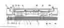
FIG. 1 is a cross-sectional view of the radiator according to the invention;
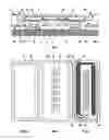
FIG. 2 is a plan view of the complete radiator;
FIG. 3 is a plan view of the radiator without the front plate;
FIG. 4 is a plan view of the radiator without the upper frame;
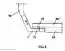
FIG. 5 is a side view of the suction head according to the invention acting on the filter.
DETAILED DESCRIPTION OF THE INVENTION
The reversible radiator shown is of the type comprising:
-
- an exchanger (1) of the type constituted by a body with fins (11) and a tubing (12) traversed by a heating or cooling heat transfer fluid;
- a means of ventilation (2) designed to draw the ambient air, to force its passage through the exchanger (1) and to eject it, heated or cooled, into the room;
- a frame (3), containing the aforementioned exchanger (1) and the aforementioned means of ventilation (2), provided with at least one air inlet opening (31) and at least one air outlet opening (32);
- a plate (4), for storing and distributing calories or frigories, attached to the front wall (33) of the aforementioned frame (3).
The originality of the invention comprises the combination of the following subassemblies:
-
- the means of generation which is constituted by a plurality of helical fans (2) supplied with low voltage direct current, positioned, side by side, along the axis of symmetry of the front wall (33) of the frame (3), facing and perpendicular to the longitudinal outlet opening (32) of the aforementioned front wall (33);
- the exchanger (1) which is made of at least two modules (13) and (14) positioned on each side of the row of fans (2), parallel to the latter;
- the air inlet opening (31) which is constituted by longitudinal openings positioned on each external side of each exchanger module (13,14), parallel to the latter,
- the plate (4), for storing and distributing calories or frigories, which is positioned at a distance from the front wall (33) of the frame (3) and is dimensioned to enable the passage of the drawn heated or cooled air and its distribution in the room between the periphery (34) of the frame (3) and the periphery of the plate (4), perpendicular to the latter.
The back part (35) of the frame (3) is leaned against the wall (9) in order to be attached to it.
Other features of the invention relate to:
-
- the plate (4), for storing and distributing calories or frigories, which is made of a material selected from among cast mineral, metal, or glass;
- the fans (2) which are attached to the frame (3) by means of elastic rubber blocks (5) of the “silentbloc®” type and that traverse a silicone sheet (6) that covers the outlet opening (32);
The tubings (12), being part of two exchanger modules (13) and (14), are connected between themselves at one end.
The free ends of the tubing (12) are connected to a motorized “4 way” valve (15).
The tubing (12) having two vertical modules (13) and (14) can be doubled so as to produce the effect of one tubing having a heat transfer fluid conveying calories and the other tubing having a heat transfer fluid conveying frigories, the free ends of the tubings (12) being connected to a “4 way” double valve.
The air inlet openings (31), which are equipped with filters (10), are made on a wall of the frame (3) which is located at a distance from the bottom of the radiator, thus from the wall on which it is posed, enabling the passage of an suction head (7), having appropriate shape and dimensions, provided with a longitudinal slot (71), directly connectable to the hose (72) of a home vacuum cleaner.
The radiator comprises:
-
- opposing each exchanger module (13) and (14), sides (36) for recuperation of condensates that flow into a tray (37);
- at the top of the tubing a means of bleeding (21);
- insulating material (8) which is installed for mixed apparatus and for cooling only apparatus but not for heating only apparatus.
It also comprises a manual or automatic means of electronic regulation of the temperature, simple to access and use, acting, depending on the temperature difference between the ambient air and the set point:
-
- on the fan speeds with the possibility of preventing any ventilation in heating mode if the temperature of the blown air is equal to or less than ambient temperature;
- on the “4 way” motorized valve(s).
- a means of remote control of one or multiple radiators by transmission via power line.
It can also comprise a booster electrical heater band (not shown) located in the volume of ventilated air or in the front plate (4).
Of course, the person of skill in the art will be able to make the invention as described and shown by applying and adapting known methods without the need to describe them or shown them.
He can also foresee other variations without departing from the scope of the invention which is determined by the content of the claims.
Claims
1. A reversible radiator comprising:
an exchanger of the type constituted by a body with fins and a tubing traversed by a heating or cooling heat transfer fluid;
a means of ventilation designed to draw the ambient air, to force its passage through the exchanger and to eject it, heated or cooled, into the room;
a frame, containing the aforementioned exchanger and the aforementioned means of ventilation, provided with an air inlet opening and an air outlet opening;
a plate, for storing and distributing calories or frigories, attached to the front wall of the aforementioned frame;
characterized in that the means of ventilation is constituted by a plurality of helical fans supplied with low voltage direct current, positioned, side by side, along the axis of symmetry of the front wall of the frame, facing and perpendicular to the longitudinal outlet opening of the aforementioned front wall;
in that the exchanger comprises two modules and positioned on each side of the row of fans, parallel to the latter;
in that the air inlet opening which is constituted by longitudinal openings positioned on each external side of each exchanger module, parallel to the latter,
and in the plate, for storing and distributing calories or frigories, is positioned at a distance from the front wall of the frame and is dimensioned to enable the passage of the drawn heated or cooled air and its distribution in the room between the periphery of the frame and the periphery of the plate, perpendicular to the latter.
2. A radiator, according to claim 1, characterized in that the plate, for storing and distributing calories or frigories, is made of a material selected from among cast mineral, metal, or glass.
3. A radiator, according to claim 1, characterized in that the fans, are attached to the frame by means of elastic rubber blocks of the “silentbloc®” type and traverse a silicone sheet that covers the outlet opening.
4. A radiator, according to claim 1, characterized in that the tubings, being part of two exchanger modules, are connected between themselves at one end.
5. A radiator, according to claim 4, characterized in that the free ends of the tubing are connected to a motorized “4 way” valve.
6. A radiator, according to claim 4, characterized in that the tubing having two vertical modules can be doubled so as to produce the effect of one tubing having a heat transfer fluid conveying calories and the other tubing having a heat transfer fluid conveying frigories, the free ends of the tubings being connected to a “4 way” double valve.
7. A radiator, according to claim 1, characterized in that the air inlet openings, which are equipped with filters, are made on a wall of the frame which is located at a distance from the bottom of the radiator, thus from the wall on which it is posed, enabling the passage of an suction head, having appropriate shape and dimensions, provided with a longitudinal slot, directly connectable to the hose of a home vacuum cleaner.
8. A radiator, according to claim 1, characterized in that it comprises, opposing each exchanger module, sides for recuperation of condensates that flow into a tray.
9. A radiator, according to claim 1, characterized in that it comprises a manual or automatic means of electronic regulation of the temperature, simple to access and use, acting, depending on the temperature difference between the ambient air and the set point:
on the fan speeds with the possibility of preventing any ventilation in heating mode if the temperature of the blown air is equal to or less than ambient temperature;
on the “4 way” motorized valve(s).
10. A radiator, according to claim 1, characterized in that it comprises a booster electrical heater band (not shown) located in the volume of ventilated air or in the front plate.
Images & Drawings included:
Sources:
- United States Patent and Trademark Office - verify current appl. status at the USPTO↗
Recent applications in this class:
- » 20250277593 2025-09-04
AIR PRE-COOLING - » 20250043973 2025-02-06
RADIATIVE COOLING DEVICE - » 20240271802 2024-08-15
COOLING PANEL SYSTEM - » 20240183548 2024-06-06
RADIATIVE COOLING STRUCTURE AND METHOD OF USING THE SAME - » 20230341137 2023-10-26
DEVICE FOR HEATING AND/OR COOLING A BUILDING - » 20220412582 2022-12-29
Systems and Methods for Tuning Radiative Heat Flows Between Interior Surfaces and Human Occupants - » 20220290879 2022-09-15
Multi-zone chilled beam system and method with pump module - » 20220235951 2022-07-28
BUILDING ENVELOPE AND METHOD FOR ADJUSTING THE TEMPERATURE IN A BUILDING - » 20210148586 2021-05-20
Radiant Panel with Fresh Air - » 20210123617 2021-04-29
Radiant panel with heat exchange device