Multi-layer ceramic heater and/or igniter and method for making the same
US20120145695A1
2012-06-14
12/963,796
2010-12-09
✅ Patent granted
US 8,901,467 B2
2014-12-02
-
-
Henry Yuen | Thomas Ward
Lowe Hauptman & Ham LLP
2031-05-31
Abstract:
A multi-layer rod shaped ceramic igniter includes an elongated tapered electrode having a central core of resistant material and two annular segments. One of the segments in on one side of the core and the other on an opposite side and connected to two slightly converging facets extending along the core. The multi-layered rod shaped ceramic igniters disclosed herein may be manufactured by slip-casting, injection molding or extruding a green annular body and removing material from opposite sides of the green body to form two almost parallel but slightly converging facets that extend over the heater igniter between the back surface and the tip of the igniter. After removing material between the annular segments the igniter is air dried and then heated in a vacuum at atmospheric pressure to approximately 900° C. in order to burn off the organic binder. The ceramic is then held in an inert atmosphere and heated to a temperature of 1600° C. and under an isotatic pressure of greater than 10 mega pascales for sintering the layer into a unitary monolithic structure.
Assignee:
- SURFACE IGNITER LLC 7 🇺🇸 Chagrin Falls, OH, United States
Applicant:
Interested in similar patents?
Get notified when new applications in this technology area are published.
Classification:
B32B38/00 IPC
Ancillary operations in connection with laminating processes
B32B37/14 IPC
Methods or apparatus for laminating, e.g. by curing or by ultrasonic bonding characterised by the properties of the layers
B32B38/10 IPC
Ancillary operations in connection with laminating processes Removing layers, or parts of layers, mechanically or chemically
B32B37/02 IPC
Methods or apparatus for laminating, e.g. by curing or by ultrasonic bonding characterised by a sequence of laminating steps, e.g. by adding new layers at consecutive laminating stations
B32B37/06 IPC
Methods or apparatus for laminating, e.g. by curing or by ultrasonic bonding characterised by the heating method
C04B2237/588 » CPC further
Aspects relating to ceramic laminates or to joining of ceramic articles with other articles by heating; Processing aspects relating to ceramic laminates or to the joining of ceramic articles with other articles by heating; Forming a gradient in composition or in properties across the laminate or the joined articles by joining layers or articles of the same composition but having different particle or grain sizes
C04B2237/368 » CPC further
Aspects relating to ceramic laminates or to joining of ceramic articles with other articles by heating; Composition of layers of ceramic laminates or of ceramic or metallic articles to be joined by heating, e.g. Si substrates; Ceramic; Non-oxidic Silicon nitride
C04B2237/76 » CPC further
Aspects relating to ceramic laminates or to joining of ceramic articles with other articles by heating; Processing aspects relating to ceramic laminates or to the joining of ceramic articles with other articles by heating Forming laminates or joined articles comprising at least one member in the form other than a sheet or disc, e.g. two tubes or a tube and a sheet or disc
C04B2235/6027 » CPC further
Aspects relating to ceramic starting mixtures or sintered ceramic products; Aspects relating to the preparation, properties or mechanical treatment of green bodies or pre-forms; Making the green bodies or pre-forms by moulding Slip casting
F23Q7/06 » CPC main
Incandescent ignition; Igniters using electrically-produced heat, e.g. lighters for cigarettes ; Electrically-heated glowing plugs structurally associated with fluid-fuel burners
C04B2235/3891 » CPC further
Aspects relating to ceramic starting mixtures or sintered ceramic products; Composition of constituents of the starting material or of secondary phases of the final product; Constituents and secondary phases not being of a fibrous nature; Non-oxide ceramic constituents or additives Silicides, e.g. molybdenum disilicide, iron silicide
B28B1/008 » CPC further
Producing shaped prefabricated articles from the material made from two or more materials having different characteristics or properties
C04B35/593 » CPC further
Shaped ceramic products characterised by their composition ; Ceramics compositions ; Processing powders of inorganic compounds preparatory to the manufacturing of ceramic products based on non-oxide ceramics based on borides, nitrides, or silicides based on silicon nitride obtained by pressure sintering
B28B1/26 » CPC further
Producing shaped prefabricated articles from the material by slip-casting, i.e. by casting a suspension or dispersion of the material in a liquid-absorbent or porous mould, the liquid being allowed to soak into or pass through the walls of the mould; Moulds therefor ; specially for manufacturing articles starting from a ceramic slip; Moulds therefor
F23Q7/001 » CPC further
Incandescent ignition; Igniters using electrically-produced heat, e.g. lighters for cigarettes ; Electrically-heated glowing plugs Glowing plugs for internal-combustion engines
C04B37/001 » CPC further
Joining burned ceramic articles with other burned ceramic articles or other articles by heating directly with other burned ceramic articles
F23Q7/22 » CPC further
Incandescent ignition; Igniters using electrically-produced heat, e.g. lighters for cigarettes ; Electrically-heated glowing plugs Details
C04B2237/582 » CPC further
Aspects relating to ceramic laminates or to joining of ceramic articles with other articles by heating; Processing aspects relating to ceramic laminates or to the joining of ceramic articles with other articles by heating; Forming a gradient in composition or in properties across the laminate or the joined articles by joining layers or articles of the same composition but having different additives
H05B6/70 IPC
Heating by electric, magnetic or electromagnetic fields; Heating using microwaves Feed lines
F23H7/00 IPC
Inclined or stepped grates
B28B1/00 IPC
Producing shaped prefabricated articles from the material
F23Q7/00 IPC
Incandescent ignition; Igniters using electrically-produced heat, e.g. lighters for cigarettes ; Electrically-heated glowing plugs
C04B37/00 IPC
Joining burned ceramic articles with other burned ceramic articles or other articles by heating
Description
FIELD OF THE INVENTION
This invention relates to a multi-layer ceramic heater and/or igniter and more particularly to electric heaters for igniting a gas in an appliance or for use in a compression type engine and to a method for manufacturing heaters/igniters with improved properties and more rapid response time.
BACKGROUND OF THE INVENTION
Ceramic heaters and igniters are well known and have been in use for many years. For example, ceramic igniters are being used extensively for igniting gas in appliances such as clothes dryers, stoves, ovens, water heaters, furnaces, pool heaters, etc. Heaters and/or igniters are also widely used for operating compression type engines or diesel engines. These heaters commonly referred to as glow plugs are installed in the engines wherein a portion of the heater extends into the combustion chamber to transfer heat to the fuel-air mixtures contained in the cylinder.
Ceramic igniters require a variety of performance requirements. For example, high speed or fast time to-temperature that is the time required to heat an element from room temperature to a temperature required for the ignition of a gas/air mixture. Another requirement for igniters is durability i.e. to operate for extended periods of time without being replaced.
A composite monolithic element for use as a hot surface igniter is disclosed in a U.S. Pat. No. 6,328,913 of Shaffer et al. As disclosed therein a hot surface igniter includes first and second regions or layers. The first region or layer comprises a low pressure ejection molded mixture of silicon carbide and silicon nitride particles or other compatible mixes which will alter processing as a resistor. The resistor includes two cold portions and a hot portion intermediate thereof. The second region or layer also includes an ejection molded mixture of silicon carbide and silicon nitride particles or other appropriate mixture, while the second layer contains the same or similar compounds as the first, the ratios of the compounds differ so that after processing it acts as an insulator and as a support for the first layer. These first and second layers are bonded together to form a joint free mechanically continuous structure and densified.
A more recent patent of mine, U.S. Pat. No. 6,610,964 relates to a multi-layer ceramic heater for igniting fuel in a diesel engine having an electrode, an insulative layer disposed over the electrode, a resistive layer disposed over the insulative layer at the tip of the heater and a conductive layer covering the insulative layer and extending from the resistive layer over the insulative layer to the base of the heater. A substantial proportion of the volume of resistive layer is located in close proximity to the tip of the heater. The resistive layer has a positive temperature coefficient (PTC) of electrical resistance and preferably a portion of the electrode is variably resistive for self-regulation purposes. Due to the geometry of the resistive layer and the variable resistive characteristics of the resistive layer and the electrode, the heater is well suited for applications that require quick start heating as well as good after glow properties or prolong heating at high temperatures.
Notwithstanding the above, it presently believed that there is a need and a potential commercial market for a multi-layer ceramic heater/igniter. There should be a need and a commercial market for such igniters because they have unique electrical properties and quick start-up from room temperature to ignition temperature. Further, such igniters are durable and capable of operating for extended periods of time without being replaced. Such igniters are also capable of being manufactured at competitive costs.
BRIEF SUMMARY OF THE INVENTION
In essence, the present invention contemplates a generally rod shaped heater/igniter comprising and/or consisting of an elongated tapered electrode having a central core of resistive material and defining two annular segments or two segments of a circle with one of the segments on each side of a core of resistant material and the other segment on an opposite end of the core. The heater/igniter also includes two slightly converging facets extending at least partially along the tip portion of the electrodes and preferably along essentially the entire electrode. The two facets are joined together by the two annular or circular segments. These annular segments are also slightly tapered and come together to form a tip of the heater igniter. The two annular segments each include a first insulative layer and a second or outer resistant layer disposed on the insulative layer and separated from the core by the insulative layer. One of the annular segments is connected to a positive source of energy while the other annular segment is connected to a negative potential for heating the tip of the heater/igniter.
The invention also contemplates a method for making a novel ceramic heater igniter that includes the step of forming a green slightly tapered rod of ceramic material as for example a silicone nitride mixed with molybdenum disilicide (MoSi2) and an insulative or non-conductive layer of silicon nitride and the step of forming a pair of slightly converging facets that converge toward the tip which preferably extend along the major part of the core to thereby form two annular segments that connect the facets and wherein the annular segments each include an insulative layer that are on opposite sides of the facets. Each of the annular segments is attached to an electrical potential wherein one of the segments is connected to a positive terminal and the other to a negative terminal.
The invention will now be described in connection with the accompanying figures wherein like reference numerals have been used to indicate like parts.
DESCRIPTION OF THE DRAWINGS
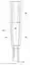
FIG. 1 is a plan view of a ceramic heater/igniter according to a first embodiment of the invention;
FIG. 2 is plan view of the heater/igniter shown in FIG. 1 but rotated by 90 degrees;
FIG. 3 is sectional view taken along the lines 3-3 in FIG. 1 of the heater/igniter shown in FIGS. 1 and 2;
FIG. 4 is an enlarged view of FIG. 3;
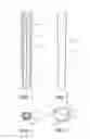
FIG. 5 is a plan view of a heater/igniter according to a second embodiment of the invention;
FIG. 6 is a plan view of the igniter shown in FIG. 5, but rotated by 90 degrees;
FIG. 7 is an end view of the igniter shown in FIG. 5;
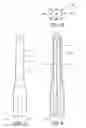
FIG. 8 is a plan view of a heater/igniter according to a third embodiment of the invention;
FIG. 9 is a plan view of the igniter shown in FIG. 8, but rotated by 90 degrees;
FIG. 10 is an end view of the igniter shown in FIGS. 8 and 9;
FIG. 11 shows a pre-form of a rod shaped element for use in manufacturing an igniter in accordance with the present invention;
FIG. 12 is a partially exploded view showing the formation of the facets of an igniter in accordance with the present invention; and
FIG. 13 is a perspective view of an igniter in accordance with the second embodiment of the present invention.
DESCRIPTION OF THE PREFERRED EMBODIMENTS OF THE INVENTION
Rod shaped ceramic igniters typically comprise a cylindrical shaped body that includes a tapered or narrow section that concentrates heat in specific areas. The present invention relates to modifying the surface layer and inner annular portion by removing material by slicing or grinding. For example, the resulting surface is planar. This modification is preferably done in the green stage after the ceramic is formed by slip-casting, injection molding, extrusion or the like. In this stage, the ceramic material can be easily removed or if not subsequently removed by a high speed grinder. The igniter body is subsequently heated in a sintering furnace, assembled in a holder with electrical leads attached in a conventional manner.
It has now been found that certain geometric modifications to an annular layered ceramic igniter/heater produce unique electrical properties as well as faster response time and may eliminate the need for a conductive core. In the present invention, a facet is cut along the length of the rod and separates an outer ceramic layer into conductive adjacent halves that are joined to create a U-shape at the heater tip. To be more specific, the facet is formed by partially cutting into or through the insulating layer to provide separation of the surface layer to thereby form a pair of “legs”. The face of the rod provides termination for attaching positive and negative electrical leads. It is also contemplated that a complex heater pattern could be made by additional faceting in the tip region to create a coil pattern to increase the length of the circuit.
Referring now to the figures, a ceramic heater/igniter 10 can be manufactured using a number of conventional steps and one non-conventional modification. For example, four ceramic compositions are prepared using conventional techniques. The various compositions are preferably selected from about 80% by volume silicone nitride and about 20% by volume molybdenum disilicide and wherein the silicone nitride particles are larger than the particle size of the molybdenum disilicide. In a preferred embodiment of the invention there are three resistant layers, one in the core and a second and third composition in the two annular segments or legs. In this embodiment all three components are about 80% by volume silicone nitride and 20% by volume molybdenum disilicide. The components of the core and in the annular segments may each contain essentially identical amounts of silicone nitride and molybdenum disilicide, but the resitivity of the core should be less than the resitivity in the annular segments and in the tip For example, particle size in the core is larger than in the annular segments to reduce the resitivity in the core while using small particles in the annular segments to increase the resitivity of those segments.
The multi-layer ceramic heater/igniter 10 also includes an insulative layer 14 between the core 12 that can be a third phase and the layer 16, 15. The insulative layer 14 may also be made of silicone nitride and molybdenum disilicide, but should contain at least 75 volume percent of non-conductive material such as silicone nitride and up to 25% by volume molybdenum disilicide.
The multi-layer ceramic heater/igniter 10 is made by slip casting to form a green body then removing material from opposite sides of the green body to form two almost parallel, but slightly converging, facets that preferably extend over at least a majority of the heater/igniter between the back surface 13 to near the tip 11. In one embodiment of the invention the two facets 18 and 20 extend over essentially the entire length of the heater/igniter 10 as can be done for a two or three phase option.
After removing the material between the annular segments 15 and 16 (FIG. 1) the heater/igniter 10 is then slowly air dried and then heated in a vacuum at atmospheric pressure to approximately 900° C. in order to burn off the organic binder. The ceramic is then held in an inert atmosphere and heated to a temperature above 1600° C. and isotatic pressure of greater than 10 megapascales for sintering the layer into a unitary monolithic structure.
The finished product is essentially pore free to prevent accelerated erosion at high temperature and to be of sufficient strength to withstand thermal cycling and vibration. The annular segments are then attached to a positive and negative source of energy in a conventional manner.
As illustrated in FIGS. 5-7 the heater/igniter 30 for a single phase only is formed by slip casting from about 80% volume silicone nitride and 20% volume molybdenum disilicide or other suitable material as will be well understood by persons of ordinary skill in the art of making multi-layer ceramic igniters. The ceramic heater/igniter 30 includes a longitudinally extending core 32 and a slightly tapered annular segment 34 is separated from the core 32 by an insulative or non-conductive layer 36 and longitudinally extending facets 38 and 40. In FIG. 6 the dotted line at the forward end of the igniter shows the end of the inside insulator 35B.
In addition, an optional cavity 39 is formed in a rear portion of the heater igniter for termination of a second phase electrical element for use of the heater/igniter.
A heater/igniter 50 for a three phase option as shown in FIGS. 8-10 is wider than the igniter shown in FIGS. 1-4 and 5-7 and primarily designed for use with a 230V 3-phase electrical circuit. The heater/igniter 50 includes a silicone nitride/molybdenum disilicide core 52 that can be an optional third phase having a tip 51 and a base end 53 and electrically insulative or non-conductive layer 55 and a tapered electrically resistive layer 56 A, B made of an material selected from the group consisting of Al2O3, Si3N4, SiC, Al3N4, SiO2, Y2O3, MgO), Zr2O3, SiAlON, MoSi2, Mo, Si3C, WSi2, TiN, TaSi2, TiB2, NbSi2, CrSi2, WC, B4C, TaN and mixtures thereof.
An electrically conductive layer 56 is disposed on the non-conductive layer 55 and about the tip 51. Two slightly converging facets 58 and 60 are separate from one another by annular or circular segment 55. In addition, an optional (cavity is formed 57) at the base end for a third phase.
FIG. 11 illustrates a multi-layer ceramic rod 70 with a resistive core 72, non-conductive layer 74 and outer resistive layer 76. Then in FIG. 12 a pair of facets are formed by removing the outer layer 76 from opposite sides of the rod 70 to form the longitudinally extending facets 78 and 80.
FIG. 13 is a perspective view illustrating the longitudinally extending slightly tapered flat surface of the facets 78 and 80 that extend over the length of the igniter 70.
While the invention has been described in connection with its preferred embodiments it should be recognized that changes and modifications may be made therein without departing from the scope of the appended claims.
Claims
What is claimed is:1. A rod shaped heater/igniter comprising an elongated tapered electrode having a central core of resistant material and defining two annular segments with one of said segments on one side of said core and the other segment on the opposite side of said core from the first of said segments and two slightly converging facets extending along said elongated electrode and joined together by said two annular segments, and said two annular segments coming together to form a tip of said heater/igniter and wherein each of said two annular segments including a first insulative layer and a second resistive layer disposed on said insulative layer and separated from said core by said insulative layer and one of said annular segments connected to a positive source of electricity and the other of said annular segments connected to a negative source for heating said tip of said heater/igniter.
2. A rod shaped heater/igniter according to claim 1 in which said annular segments are circular segments.
3. A rod shaped heater/igniter according to claim 1 in which said electrode has a positive temperature coefficient of electrical resistance.
4. A rod shaped heater/igniter according to claim 1 in which said resistive layer has a positive temperature coefficient of electrical resistance.
5. A rod shaped heater/igniter according to claim 4 in which said insulative layer is made from a composition which is at least 75% volume of electrically non-conductive material and up to 5% volume sintering additives and wherein the ceramic components are selective from the group consisting of Al2O3, Si3N4, SiC, Al3N4, SiO2, Y2O3, MgO), Zr2O3, SiAlON, MoSi2, Mo, Si3C, WSi2, TN, TaSi2, TiB2, NbSi2, CrSi2, WC, B4C, TaN and mixtures thereof.
6. A rod shaped heater/igniter according to claim 5 in which said electrodes and said resistive layers are made from silicone nitride and molybdenum disilicide.
7. A multi-layer rod shaped ceramic igniter consisting of an elongated tapered electrode having a central core of resistant material and two circular segments with one of said segments on one side of said core and the second of said segments on an opposite side of said core from the first side and two slightly converging facets extending along said core and joined together by said circular segments and coming together to form a tip of said igniter and wherein said two circular segments include a first insulative layer and a second resistive layer disposed on said insulative layer and separated from said core by said insulative layer and wherein said core in said circular segments are made if silicon nitride and molybdenum disilicide and one of said circular segments is connected to a positive potential and the other of said circular segments is connected to a negative potential.
8. A method for making a multi-layer ceramic heater/igniter comprising the steps of:
mixing a first and a second resistive compound and a third non-conductive compound and wherein said first and second compounds when formed into a core and an outer layer have different resitivities;
forming a multi-layer green body from said compounds and adding an organic binder and subsequently forming a green body by slip casting and air drying said green body;
forming two longitudinally extending slightly converging facets and two slightly converging annular segments connecting said facets in a unitary structure;
heating said green body to at least 900° C. to remove the organic binder and subsequently heating to at least 1600° C. to sinter said body into a unitary monolithic structure;
separating said outer layer into two legs; and
attaching one of said legs to a positive anode and the other leg to a cathode to thereby form an multi-layer ceramic igniter.
9. A method for making a multi-layer ceramic heater/igniter consisting of:
mixing a first and a second resistive compound and a third non-conductive compound and wherein said first and second compounds when formed into a core and an outer layer have different resitivities;
forming a multi-layer green body from said compounds and adding an organic binder and subsequently forming a green body by slip casting and air drying said green body;
forming two longitudinally extending slightly converging facets and two slightly converging annular segments connecting said facets in a unitary structure;
heating said green body to at least 900° C. to remove the organic binder and subsequently heating to at least 1600° C. to sinter said body into a unitary monolithic structure;
separating said outer layer into two legs; and
attaching one of said legs to a positive anode and the other leg to a cathode to thereby form an multi-layer ceramic igniter.
Images & Drawings included:


Sources:
- United States Patent and Trademark Office - verify current appl. status at the USPTO↗
Recent applications in this class:
- » 20120196235 2012-08-02
Ignition device
Recent applications for this Assignee:
- » 20210388967 2021-12-16
Infrared source for airport runway light applications - » 20200332983 2020-10-22
Infrared source for airport runway light applications - » 20160046172 2016-02-18
Heating system for a motor vehicle - » 20110305920 2011-12-15
On the production of metal-ceramic compounds - » 20100291498 2010-11-18
Shock absorbing assembly for gas igniter - » 20070215591 2007-09-20
Mounting device gas igniter