Prism type lens
US20120147481A1
2012-06-14
12/964,080
2010-12-09
✅ Patent granted
US 8,248,710 B2
2012-08-21
-
-
Mohammed Hasan
2031-02-15
Abstract:
A prism type of lens includes a first reflection lens, at least a first lens group, a second reflection prism, at least a second lens group, a third reflection prism, and at least a third lens group sequentially arranged from an object side to an image side. Light is reflected by the reflection prisms to form a bent light axis. Therefore, the optical axis has three sections for the lens groups to move respectively. The bent light axis has a longer distance that the lens of the present invention may have a great zoom range.
Assignee:
- ASIA OPTICAL CO., INC. 473 🇹🇼 Taichung, Taiwan
Interested in similar patents?
Get notified when new applications in this technology area are published.
Classification:
G02B15/14 IPC
Optical objectives with means for varying the magnification by axial movement of one or more lenses or groups of lenses relative to the image plane for continuously varying the equivalent focal length of the objective
G02B5/04 » CPC further
Optical elements other than lenses Prisms
G02B7/102 » CPC main
Mountings, adjusting means, or light-tight connections, for optical elements for lenses with mechanism for focusing or varying magnification by relative axial movement of several lenses, e.g. of varifocal objective lens controlled by a microcomputer
G02B13/0035 » CPC further
Optical objectives specially designed for the purposes specified below; Miniaturised objectives for electronic devices, e.g. portable telephones, webcams, PDAs, small digital cameras characterised by the lens design having at least one aspherical surface having three lenses
G02B13/007 » CPC further
Optical objectives specially designed for the purposes specified below; Miniaturised objectives for electronic devices, e.g. portable telephones, webcams, PDAs, small digital cameras employing a special optical element having a beam-folding prism or mirror the beam folding prism having at least one curved surface
G02B13/009 » CPC further
Optical objectives specially designed for the purposes specified below; Miniaturised objectives for electronic devices, e.g. portable telephones, webcams, PDAs, small digital cameras having zoom function
G02B15/143 » CPC further
Optical objectives with means for varying the magnification by axial movement of one or more lenses or groups of lenses relative to the image plane for continuously varying the equivalent focal length of the objective having three groups only
G02B17/0896 » CPC further
Systems with reflecting surfaces, with or without refracting elements; Catadioptric systems with variable magnification or multiple imaging planes, including multispectral systems
G02B3/00 » CPC further
Simple or compound lenses
G02B23/08 » CPC further
Telescopes, e.g. binoculars; Periscopes; Instruments for viewing the inside of hollow bodies; Viewfinders; Optical aiming or sighting devices involving prisms or mirrors Periscopes
G02B7/10 IPC
Mountings, adjusting means, or light-tight connections, for optical elements for lenses with mechanism for focusing or varying magnification by relative axial movement of several lenses, e.g. of varifocal objective lens
G02B17/08 IPC
Systems with reflecting surfaces, with or without refracting elements Catadioptric systems
Description
BACKGROUND OF THE INVENTION
1. Field of the Invention
The present invention relates generally to a lens, and more particularly to a prism type lens.
2. Description of the Related Art
As an improvement of technology, many electronic products, such as cellular phone, videogame, PDA etc., are equipped with image capture device for people to record his/her everyday life.
A conventional lens for the image capture device is cylinder cam type lens which has a plurality of lens groups. The lens groups are adjusted for focusing. The lens groups of the cylinder cam type lens will be moved into the image capture device when people turn off the electronic product. As there may be too many lens groups to be moved, sometime the cylinder cam type lens is too big for some image capture devices.
An improved lens, a prism type lens, is provided to overcome the drawback of the cylinder cam type lens. Taiwan Utility Model Patent No. M376769 discloses a prism type lens including a plurality of lens groups received in an image capture device for reciprocation and a prism for total reflection to reflect incident light to the lens groups. The prism type lens equips the image capture device with no protruded lens that the image capture device may be smaller and lighter.
However, the prism type lens has a limitation in zoom range because the lens groups have to move along a straight path and there is insufficient distance for the lens groups to move. The zoom range may be enlarged by lengthening the optical axis. However, it will increase the size of the image capture device.
SUMMARY OF THE INVENTION
The primary objective of the present invention is to provide a prism type lens with a great zoom range.
According to the objective of the present invention, a prism type of lens includes a first reflection lens, at least a first lens group, a second reflection prism, at least a second lens group, a third reflection prism, and at least a third lens group sequentially arranged from an object side to an image side. Light is reflected by the reflection prisms to form a bent light axis. The optical axis has a first section between the first reflection prism and the second reflection prism, a second section between the second reflection prism and the third reflection prism, and a third section between the third reflection prism and the image side. The second section is substantially perpendicular to the first section and the third section is substantially perpendicular to the second section. The first lens group is in the first section, the second lens group is in the second section, and the third lens group 103 is in the third section.
BRIEF DESCRIPTION OF THE DRAWINGS
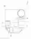
FIG. 1 is a perspective view of a first preferred embodiment of the present invention;
FIG. 2 is a sectional view of the first section of the light axis of the first preferred embodiment of the present invention;
FIG. 3 is a sectional view of the first preferred embodiment of the present invention, showing three drivers moving the first, second, and third lens groups respectively;
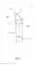
FIG. 4 is a sectional view of a second preferred embodiment of the present invention.
DETAILED DESCRIPTION OF THE INVENTION
As shown in FIG. 1 and FIG. 2, a prism type lens 1 of the first preferred embodiment of the present invention includes an optical lens 10, a first reflection lens 21, a first lens group 31, a second reflection prism 22, a second lens group 32, a third reflection prism 23, and a third lens group 33 sequentially arranged from an object side 110 to an image side 111. An image sensor 40 is provided at the image side 111.
The reflection prisms 21˜23 reflect light for a 90 degrees turn. A U-shaped light axis 100 is formed by the reflection prisms 22˜23. The light axis 100 is divided into a first section 101 between the first reflection prism 21 and the second reflection prism 22, a second section 102 between the second reflection prism 22 and the third reflection prism 23, and a third section 103 between the third reflection prism 23 and the image sensor 40. The first section 101 is perpendicular to the second section 102, and the third section 103 is perpendicular to the second section 102. With these reflection prisms 21˜23 a length of the optical axis 100 is lengthened.
As shown in FIG. 1, the first lens group 31 is in the first section 101, the second lens group 32 is in the second section 102, and the third lens group 33 is in the third section 103. A driver 50 is provided to drive the lens groups 31, 32, and 33 for reciprocation in the first, second and third sections 101, 102, and 103 respectively. Distances for the lens groups 31, 32, 33 to move is longer because of the longer optical axis 100 that the lens 1 of the present invention may provide a great zoom range. In drawings, the lens groups each has a single lens, and in practice the lens group may have a single lens, multi-lenses, a single composite lens, or multi-composite lenses.
There is a space 60 within the three sections 101˜103, and the driver 50 is provided in the space 60, which means the optical axis 100 around the driver 50 will not increase the size of the lens 1 by being lengthened. It also may provide controllers for focusing, optical shielding, or stabilization in the space 60 that the lens 1 of the present invention may have great zoom range and still remain small.
FIG. 3 shows that three drivers 51˜53 are received in the space 60 to drive the lens groups 31, 32, 33 respectively. Three drivers may provide a precise control on the lens groups, and it will not increase the size of the lens 1.
In conclusion, the present invention provides the reflection prisms to create a bent optical axis that the lens of the present invention may have a great zoom range. The present invention also uses the space within the bent optical axis to receive other elements that the lens may remain small.
FIG. 4 shows a prism type lens 2 of the second preferred embodiment of the present invention, which is similar to the first preferred embodiment, except that the third reflection prism reflects light downward to form an S-shaped optical axis 200. The optical axis 200 still has three sections, and the third section 203 is downwards. The optical axis 200 divides the lens 2 that there are two spaces 71 and 72 in the lens 2, with the space 71 above the second section 202, and the space 72 under the second section 202. The spaces 71 and 72 receive more devices therein. For some reasons, some devices cannot be too close to other devices because it may generate interference or other problems. The spaces 71 and 72 may provide sufficient space for such devices.
The description above is a few preferred embodiments of the present invention and the equivalence of the present invention is still in the scope of claim construction of the present invention.
Claims
What is claimed is:1. A prism type of lens, comprising a first reflection lens, at least a first lens group, a second reflection prism, at least a second lens group, a third reflection prism, and at least a third lens group sequentially arranged from an object side to an image side;
wherein light is reflected by the reflection prisms to form a bent light axis, which has a first section between the first reflection prism and the second reflection prism, a second section between the second reflection prism and the third reflection prism, and a third section between the third reflection prism and the image side;
wherein the second section is substantially perpendicular to the first section and the third section is substantially perpendicular to the second section;
wherein the first lens group is in the first section, the second lens group is in the second section, and the third lens group is in the third section.
2. The prism type of lens as defined in claim 1, further comprising a driver to drive the first lens group for reciprocation along the first section of the optical axis.
3. The prism type of lens as defined in claim 2, wherein a space is formed by the optical axis to receive the driver therein.
4. The prism type of lens as defined in claim 1, further comprising a driver to drive the second lens group for reciprocation along the second section of the optical axis.
5. The prism type of lens as defined in claim 4, wherein a space is formed by the optical axis to receive the driver therein.
6. The prism type of lens as defined in claim 1, further comprising a driver to drive the third lens group for reciprocation along the third section of the optical axis.
7. The prism type of lens as defined in claim 6, wherein a space is formed by the optical axis to receive the driver therein.
8. The method as defined in claim 1, further comprising a driver to drive the first lens group, the second lens group and the third lens group for reciprocation along the first section, the second section and the third section of the optical axis respectively.
9. The method as defined in claim 8, wherein a space is formed by the optical axis to receive the driver therein.
10. The method as defined in claim 1, further comprising an optical lens on the optical axis which is closer to object side than the first reflection prism.
Images & Drawings included:


Sources:
- United States Patent and Trademark Office - verify current appl. status at the USPTO↗
Similar patent applications:
- » 20110051243
PRISM TYPE LENS STRUCTURE
Recent applications in this class:
- » 20250271633 2025-08-28
Optical Zoom Camera Module and Corresponding Portable Terminal Device - » 20250251566 2025-08-07
APPARATUS AND IMAGE PICKUP APPARATUS - » 20250251565 2025-08-07
DRIVING ASSEMBLY, ZOOM LENS AND CAMERA DEVICE - » 20250237847 2025-07-24
CAMERA MODULE DRIVING APPARATUS - » 20250231374 2025-07-17
CAMERA MODULE AND CAMERA APPARATUS COMPRISING SAME - » 20250208375 2025-06-26
OPTICAL ELEMENT DRIVING MECHANISM - » 20250189756 2025-06-12
CONTROL APPARATUS, LENS APPARATUS, IMAGE PICKUP APPARATUS, CONTROL METHOD, AND STORAGE MEDIUM - » 20250004243 2025-01-02
LENS DRIVING DEVICE AND CAMERA DEVICE COMPRISING SAME - » 20240418960 2024-12-19
CONTROL SYSTEM OF LINEAR ACTUATOR, LENS APPARATUS, IMAGE CAPTURING APPARATUS, CONTROL METHOD OF LINEAR ACTUATOR, AND STORAGE MEDIUM - » 20240361569 2024-10-31
LENS APPARATUS AND IMAGE PICKUP APPARATUS
Recent applications for this Assignee:
- » 20240361104 2024-10-31
AIMING DEVICES AND METHODS THEREOF - » 20230288683 2023-09-14
Optical system - » 20230194256 2023-06-22
Range finder and lens assembly for display thereof - » 20230047206 2023-02-16
Lens device capable of operation of multi-magnifications, optical zoom in high magnification, and miniaturization of the lens module thereof - » 20230018568 2023-01-19
Lens Device - » 20220413278 2022-12-29
Compensating mechanism - » 20220390812 2022-12-08
Lens driving devices and driving methods thereof - » 20220390722 2022-12-08
WIDE-ANGLE LENS ASSEMBLY - » 20220373296 2022-11-24
Sight and compensating mechanism thereof - » 20220357564 2022-11-10
Optical device