Braking device for rotating shaft and gear motor system using the same
US20120152047A1
2012-06-21
13/402,862
2012-02-22
✅ Patent granted
US 8,826,764 B2
2014-09-09
-
-
Troy Chambers | Zakaria Elahmadi
Matthias Scholl P.C. | Matthias Scholl
2032-02-22
Abstract:
A braking device for a rotating shaft and a gear motor system using the same. The braking device includes a brake subassembly, a rotating shaft, and a sleeve. The rotating shaft is sheathed with the sleeve. The brake subassembly includes an adjustable screw, a spring, and a brake disc. One end of the spring presses on top of the brake disc and the other end presses at the bottom of the adjustable screw. After the adjustable screw is fixed, the bottom surface of the brake disc is tightly against the outer surface of the sleeve. When the adjustable screw is adjusted, the amount of compression of the spring is changed and the pressure imposed on the brake disc by the spring varies accordingly such that the friction between the brake disc and the sleeve is changed.
Assignee:
- Zhongshan Broad-Ocean Motor Manufacturing Co., Ltd. 52 🇨🇳 Zhongshan, China
Applicant:
Interested in similar patents?
Get notified when new applications in this technology area are published.
Classification:
Y10T74/19633 » CPC further
Machine element or mechanism; Gearing Yieldability in gear trains
Y10T74/19637 » CPC further
Machine element or mechanism; Gearing with brake means for gearing
Y10T74/19828 » CPC further
Machine element or mechanism; Gearing; Directly cooperating gears; Spiral Worm
F16D49/00 IPC
Brakes
F16D49/00 IPC
Brakes with a braking member co-operating with the periphery of a drum, wheel-rim, or the like
F16H1/16 IPC
Toothed gearings for conveying rotary motion without gears having orbital motion involving only two intermeshing members with non-parallel axes comprising worm and worm-wheel
H02K7/116 IPC
Arrangements for handling mechanical energy structurally associated with dynamo-electric machines, e.g. structural association with mechanical driving motors or auxiliary dynamo-electric machines; Structural association with clutches, brakes, gears, pulleys or mechanical starters with gears
H02K7/102 » CPC further
Arrangements for handling mechanical energy structurally associated with dynamo-electric machines, e.g. structural association with mechanical driving motors or auxiliary dynamo-electric machines; Structural association with clutches, brakes, gears, pulleys or mechanical starters with friction brakes
H02K7/1166 » CPC main
Arrangements for handling mechanical energy structurally associated with dynamo-electric machines, e.g. structural association with mechanical driving motors or auxiliary dynamo-electric machines; Structural association with clutches, brakes, gears, pulleys or mechanical starters with gears where at least two gears have non-parallel axes without having orbital motion comprising worm and worm-wheel
Description
CROSS-REFERENCE TO RELATED APPLICATIONS
This application is a continuation of International Patent Application No. PCT/CN2010/076346 with an international filing date of Aug. 25, 2010, designating the United States, now pending, and further claims priority benefits to Chinese Patent Application No. 200920193959.6 filed Sep. 1, 2009. The contents of all of the aforementioned applications, including any intervening amendments thereto, are incorporated herein by reference.
BACKGROUND OF THE INVENTION
1. Field of the Invention
The invention relates to a braking device for a rotating shaft and a gear motor system using the same.
2. Description of the Related Art
Conventionally, a gear motor is used as a driving device for opening and closing rolling doors of garages and warehouses as it has a compact structure, large torque, and slow rotational speed. To ensure such garage or warehouse doors can immediately stay at a certain position at the time of power outage or manual stop, a braking device or a brake is required to consume the inertia to prevent the doors from sliding down freely due to the gravity to ensure the personal safety. However, because conventional braking devices for gear motors employ electromagnetic braking modes, they are complicated in structure and high in costs.
SUMMARY OF THE INVENTION
In view of the above-described problems, it is one objective of the invention to provide a braking device for a rotating shaft that has a simple structure, low costs, and excellent braking performance.
Another objective of the invention is to provide a gear motor system, which has compact structure and is equipped with a breaking device with simple structure, low costs and excellent braking performance.
To achieve the above objective, in accordance with one embodiment of the invention, there is provided a braking device for a rotating shaft comprising a brake subassembly, a rotating shaft, and a sleeve, wherein the rotating shaft is sheathed with the sleeve, the brake subassembly comprises an adjustable screw, a spring, and a brake disc, one end of the spring presses on the top of the brake disc and the other end presses at the bottom of the adjustable screw; after the adjustable screw is fixed, the bottom surface of the brake disc is tightly against the outer surface of the sleeve; when the adjustable screw is adjusted, the amount of compression of the spring is changed and the pressure imposed on the brake disc by the spring varies accordingly, so that the friction between the brake disc and the sleeve is changed.
In a class of this embodiment, the sleeve is a bushing.
In a class of this embodiment, a contact surface directly formed between the brake disc and the sleeve is an arc-shaped surface.
In a class of this embodiment, the brake disc is made of carbon/carbon composition brake material.
In accordance with another embodiment of the invention, there is provided a gear motor system comprising a motor, a reduction gear assembly, a gear box, and a brake subassembly, wherein the gear box is disposed at a shaft extension end of the motor and the reduction gear assembly is disposed in the gear box; a rotating shaft in the high-speed running motor is output by a gear shaft after it is reduced by the reduction gear assembly; the rotating shaft is sheathed with a sleeve, which is attached with the rotating shaft; the brake subassembly comprises an adjustable screw, a spring, and a brake disc, and one end of the spring presses on the top of the brake disc and the other end presses at the bottom of the adjustable screw; after the adjustable screw is fixed, the bottom surface of the brake disc is tightly against the outer surface of the sleeve; when the adjustable screw is adjusted, the amount of compression of the spring is changed and the pressure imposed on the brake disc by the spring varies accordingly, so that the friction between the brake disc and the sleeve is changed.
In a class of this embodiment, the gear box is disposed with a through hole, in which the brake subassembly comprising the adjustable screw, the spring, and the brake disc is arranged. The adjustable screw is disposed at the outer end of the through hole and the brake disc extends out of the bottom of the through hole and tightly presses on the sleeve.
In a class of this embodiment, the gear box comprises a box body and a front end cover. The reduction gear assembly comprises a gear, a gear shaft, and a worm that is at the end of the rotating shaft, in which the worm engages with the gear, the gear is disposed on the gear shaft, the gear shaft is disposed in a bearing seat of the box body through bearings.
In a class of this embodiment, the sleeve is a bushing.
In a class of this embodiment, a contact surface directly formed between the brake disc and the sleeve is an arc-shaped surface.
In a class of this embodiment, the brake disc is made of carbon/carbon composition brake material.
Advantages of the invention are summarized below:
-
- 1) the mechanical braking device, which comprises an adjustable screw, a spring, and a brake disc, has a simple and compact structure, low costs, and excellent braking performance;
- 2) when the brake disc wears, it is possible to adjust the tightness of the adjustable screw to compress the spring so as to allow the brake disc to tightly press on the sleeve of the rotating shaft; and
- 3) the contact surface directly formed between the brake disc and the sleeve is designed to be an arc-shaped surface, which closely contacts with the outer surface of the sleeve. Such a structure has larger contact area and larger friction bearing area, thus the optimum braking performance can be achieved.
BRIEF DESCRIPTION OF THE DRAWINGS
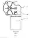
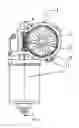
FIG. 1 is an overall structure diagram of a motor assembly in accordance with one embodiment of the invention;
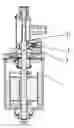
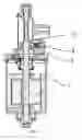
FIG. 2 is a structural representation of an exploded brake subassembly of FIG. 1;
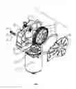
FIG. 3 is an overall exploded view of FIG. 1;
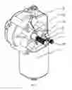
FIG. 4 is a structural representation of a gear box of the invention without gaskets and a front end cover;
FIG. 5 is a sectional view of FIG. 4 taken from the line A-A; and
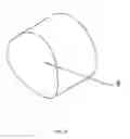
FIG. 6 is a structural representation of a brake disc in accordance with one embodiment of the invention.
DETAILED DESCRIPTION OF THE EMBODIMENTS
As shown in FIGS. 1-6, a gear motor system, in accordance with the invention, comprises a motor 1, a reduction gear assembly 2, a gear box 3, and a brake subassembly 4. The gear box 3 is disposed at the shaft extension end of the motor and the reduction gear assembly 2 is disposed in the gear box 3. A rotating shaft 11 in the high-speed running motor 1 is output by a gear shaft 22 after it is reduced by the reduction gear assembly 2. The rotating shaft 11 is sheathed with a sleeve 5, which is attached with the rotating shaft 11. The brake subassembly 4 and the rotating shaft 11 form the braking device of the gear motor system. The brake subassembly 4 comprises an adjustable screw 6, a spring 7 and a brake disc 8, in which one end of the spring 7 presses on the top of the brake disc 8 and the other end presses at the bottom of the adjustable screw 6. After the adjustable screw 6 is fixed, the bottom surface of the brake disc 8 is tightly against the outer surface of the sleeve 5. When the adjustable screw 6 is adjusted, the amount of compression of the spring 7 can be changed and the pressure imposed on the brake disc 8 by the spring 7 varies accordingly, so that the friction between the brake disc 8 and the sleeve 5 is changed.
The gear box 3 is disposed with a through hole 33, in which the brake subassembly 4 that is composed of the adjustable screw 6, the spring 7 and the brake disc 8 is arranged. The adjustable screw 6 is disposed at the outer end of the through hole 33 and the brake disc 8 extends out of the bottom of the through hole 33 and tightly presses on the sleeve 5. The gear box 3 comprises a box body 31 and a front end cover 35. The reduction gear assembly 2 comprises a gear 21, a gear shaft 22 and a worm 15 that is at the end of the rotating shaft, in which the worm 15 engages with the gear 21, the gear 21 is disposed on the gear shaft 22, the gear shaft 22 is disposed in a bearing seat 32 of the box body 31 through bearings. The sleeve 5 can be a bushing. A contact surface 9 directly formed between the brake disc 8 and the sleeve 5 is an arc-shaped surface. The brake disc 8 is made of carbon/carbon composition brake material.
The braking device of the invention has the advantages of a simple structure, low costs, and excellent braking performance. When garage or warehouse doors tend to slide down freely due to the gravity after immediately staying at a certain position at the time of power outage or manual stop, the adjustable screw 6 can be pre-adjusted to increase the amount of compression of the spring 7, which further increases the pressure on the brake disc 8 to increase the friction between the brake disc 8 and the sleeve 5, therefore excellent mechanical brake and personal safety are achieved.
Claims
The invention claimed is:1. A braking device for a rotating shaft, comprising:
a) a brake subassembly;
b) a rotating shaft; and
c) a sleeve;
wherein
the rotating shaft is sheathed with the sleeve;
the brake subassembly comprises an adjustable screw, a spring, and a brake disc, and one end of the spring presses on the top of the brake disc and the other end presses at the bottom of the adjustable screw;
after the adjustable screw is fixed, the bottom surface of the brake disc is tightly against the outer surface of the sleeve;
when the adjustable screw is adjusted, the amount of compression of the spring is changed and the pressure imposed on the brake disc by the spring varies accordingly, so that the friction between the brake disc and the sleeve is changed.
2. The braking device for a rotating shaft of claim 1, wherein the sleeve is a bushing.
3. The braking device for a rotating shaft of claim 1, wherein a contact surface directly formed between the brake disc and the sleeve is an arc-shaped surface.
4. The braking device for a rotating shaft of claim 1, wherein the brake disc is made of carbon/carbon composition brake material.
5. The braking device for a rotating shaft of claim 2, wherein the brake disc is made of carbon/carbon composition brake material.
6. The braking device for a rotating shaft of claim 3, wherein the brake disc is made of carbon/carbon composition brake material.
7. A gear motor system, comprising:
a) a motor;
b) a reduction gear assembly;
c) a gear box; and
d) a brake subassembly;
wherein
the gear box is disposed at a shaft extension end of the motor and the reduction gear assembly is disposed in the gear box;
a rotating shaft in the high-speed running motor is output by a gear shaft after it is reduced by the reduction gear assembly;
the rotating shaft is sheathed with a sleeve, which is attached with the rotating shaft;
the brake subassembly comprises an adjustable screw, a spring, and a brake disc, and one end of the spring presses on the top of the brake disc and the other end presses at the bottom of the adjustable screw;
after the adjustable screw is fixed, the bottom surface of the brake disc is tightly against the outer surface of the sleeve; and
when the adjustable screw is adjusted, the amount of compression of the spring is changed and the pressure imposed on the brake disc by the spring varies accordingly, so that the friction between the brake disc and the sleeve is changed.
8. The gear motor system of claim 7, wherein
the gear box is disposed with a through hole, in which the brake subassembly comprising the adjustable screw, the spring, and the brake disc is arranged; and
the adjustable screw is disposed at the outer end of the through hole and the brake disc extends out of the bottom of the through hole and presses on the sleeve.
9. The gear motor system of claim 7, wherein
the gear box comprises a box body and a front end cover;
the reduction gear assembly comprises a gear, a gear shaft, and a worm that is at the end of the rotating shaft;
the worm engages with the gear;
the gear is disposed on the gear shaft; and
the gear shaft is disposed in a bearing seat of the box body through bearings.
10. The gear motor system of claim 8, wherein
the gear box comprises a box body and a front end cover;
the reduction gear assembly comprises a gear, a gear shaft, and a worm that is at the end of the rotating shaft;
the worm engages with the gear;
the gear is disposed on the gear shaft; and
the gear shaft is disposed in a bearing seat of the box body through bearings.
11. The gear motor system of claim 9, wherein the sleeve is a bushing.
12. The gear motor system of claim 10, wherein the sleeve is a bushing.
13. The gear motor system of claim 7, wherein a contact surface directly formed between the brake disc and the sleeve is an arc-shaped surface.
14. The gear motor system of claim 8, wherein a contact surface directly formed between the brake disc and the sleeve is an arc-shaped surface.
15. The gear motor system of claim 7, wherein the brake disc 8 is made of carbon/carbon composition brake material.
16. The gear motor system of claim 8, wherein the brake disc 8 is made of carbon/carbon composition brake material.
Images & Drawings included:
Sources:
- United States Patent and Trademark Office - verify current appl. status at the USPTO↗
Recent applications in this class:
- » 20240195263 2024-06-13
DRIVE DEVICE, IN PARTICULAR ADJUSTMENT DRIVE, IN A MOTOR VEHICLE - » 20240162783 2024-05-16
MOTOR WITH DECELERATION MECHANISM - » 20240154494 2024-05-09
DRIVING MOTOR HAVING BLDC MOTOR AND SWIVEL ACTUATOR USING THE SAME - » 20230387749 2023-11-30
DRIVING MOTOR EQUIPPED WITH BLDC MOTOR, AND ACTUATOR USING SAME - » 20230369939 2023-11-16
DRIVE MOTOR PROVIDED WITH BLDC MOTOR AND SWIVEL ACTUATOR USING SAME - » 20230307990 2023-09-28
Speed reduction device for motor - » 20230261544 2023-08-17
Driving motor having BLDC motor and swivel actuator using same - » 20230155450 2023-05-18
Motor - » 20230009231 2023-01-12
GEAR BOX - » 20220399780 2022-12-15
Wiper motors and methods of manufacture and use thereof
Recent applications for this Assignee:
- » 20170085140 2017-03-23
Plastic-packaged stator and external rotor motor comprising the same - » 20170074273 2017-03-16
Blower comprising a pressure measuring connector - » 20160254712 2016-09-01
Rotor with embedded permanent magnets, assembly structure and motor comprising the same - » 20150372555 2015-12-24
Wire terminal joint of motor stator winding - » 20150372549 2015-12-24
Motor - » 20150229171 2015-08-13
Permanent magnet rotor - » 20150162860 2015-06-11
Method for controlling three-phase brushless DC motor comprising single hall sensor - » 20150162792 2015-06-11
Permanent magnet rotor - » 20150091482 2015-04-02
Variable speed fan motor - » 20140183983 2014-07-03
Plastic-package motor