Advanced stopper head
US20120160799A1
2012-06-28
13/332,929
2011-12-21
✅ Patent granted
US 8,684,207 B2
2014-04-01
-
-
Mickey Yu | Niki Eloshway
Young & Thompson
2032-01-10
Abstract:
A stopper head (1) to be secured to a stopper body (2) to form a stopper for a container, includes a base (3) on which a lug (4) is positioned such that it protrudes, the lug (4) being designed to cooperate with the body during the assembly of the body and the lug (4), the lug (4) including at least one recess (5) opening laterally, at both of its ends, such that the lug (4) is crossed through to anchor the body with the head (1).
Assignee:
- LES BOUCHAGES DELAGE 1 🇫🇷 GENSAC LA PALLUE, France
Applicant:
Interested in similar patents?
Get notified when new applications in this technology area are published.
Classification:
B65D39/0058 » CPC main
Closures arranged within necks or pouring openings or in discharge apertures, e.g. stoppers made in more than one piece from natural or synthetic cork, e.g. for wine bottles or the like
B65D39/00 IPC
Closure members for rigid or semi-rigid containers or for flexible containers presenting similar closing problems ; Parts of containers co-operating with closure members or characterised by the form of closure member
B65D39/00 IPC
Closures arranged within necks or pouring openings or in discharge apertures, e.g. stoppers
B65D39/16 » CPC further
Closures arranged within necks or pouring openings or in discharge apertures, e.g. stoppers with handles or other special means facilitating manual actuation
Description
This invention relates to a stopper head. It also relates to a stopper for a container, like what is used to seal a bottle.
There are stoppers that comprise a cylindrical portion made of cork or a synthetic material, also called a stopper body, one end of which is secured to a plastic head by gluing.
These stoppers for the food industry must meet very strict standards.
However, the use of glues that are suitable for contact with food cannot guarantee due to the limitations of their chemical composition full adhesion in an environment that is subject to extreme conditions.
There have been attempts to solve this problem by providing, successively:
- stoppers whose bond between the stopper head and body is enhanced by a solid cylindrical element that protrudes and enters into a blind hole in the stopper body,
- stoppers without glue, whose bond between the stopper head and stopper body is formed by overmolding.
However, it is often observed that the stopper body separates from the head when opening a bottle fitted with such a stopper because of adhesion problems between these elements.
During use, this assembly is effectively subject to tensile mechanical stress, which could result in tearing the stopper head.
The strength of the bond, or attachment, between the stopper body and the stopper head must therefore be increased.
This invention aims to overcome these drawbacks by providing a stopper head that is simple in its design and operation and economical, providing a better attachment between the stopper head and the stopper body.
As such, the invention relates to a stopper head to be secured to a stopper body to form a stopper for a container.
According to the invention, this head comprises a base on which a lug is positioned such that it protrudes, said lug being designed to cooperate with said body during the assembly of this body and this lug. This lug comprises at least one recess opening laterally at both of its ends, such that said lug is crossed through to anchor said body with said head.
Purely as an example, this head can be made of metal, wood, or even plastic.
The stopper head can be one piece or the result of mounting a lug onto a base. For example, this mounting can be achieve by welding.
By “one piece”, it is meant that this clip is made from one part, not as a result of assembling originally separate parts.
In various particular embodiments of this stopper head, each having its particular advantages and open to many possible technical combinations:
-
- Because the lug has an elongated shape, said recess has a flared shape in the longitudinal direction of the lug, the widest part of the recess being positioned on the side of the free end of said lug,
This free end is defined opposite the other end of the lug, which is secured to the base of the stopper head.
This flared shape of the recess advantageously improves the flow of the plastic during the overmolding of the stopper body around the lug. Also, it provides additional material support in the area where the body and lug are molded together, which is the most heavily prone to tearing.
This flared shape of the recess represents balance between improving the attachment of the stopper body to the stopper head and weakening the lug.
-
- Said lug has rotational asymmetry to prevent said body from rotating around said lug,
The lug therefore does not have a rotational symmetry. It can have an elliptical, egg-shaped, or potato-shaped cross-section, for example.
Alternatively, the lug may comprise at least one edge to block the rotation of said body. In this latter case, the lug may have a polygonal cross-section, such as a square, rhombus, etc.
-
- This head comprises at least one element to mechanically stiffen the lug, this mechanically stiffening element being secured to said base and to said lug.
Preferably, it is a stiffening rib.
Advantageously, said at least one stiffening element has a shape designed to cooperate with said body in order to block its rotation.
This shape can be a stiffening rib having a flat portion arranged such that it blocks the movement of the stopper body.
-
- Said base comprises on its receiving face said lug, attachment elements projecting from said base and/or a groove to strengthen the adhesion of said body with said head.
These attachment elements, with longitudinal dimensions that are less than those of the lug, form a relief that engages into the stopper body during the overmolding, thereby strengthening the adhesion of the stopper body and the stopper head.
The base may have on its receiving face the lug or a continuous or non-continuous groove, designed to accommodate part of the stopper body during the assembly of this body with the stopper head so that this stopper body is secured not only to the lug, but also to the base. The attachment of the stopper body and the stopper head is thus strengthened. This groove may, for example, be in the shape of a continuous or non-continuous circular recess, surrounding the lug.
-
- Said lug is rough to strengthen the adhesion of said stopper body with said head.
The invention further relates to a stopper for a container, consisting of two different materials and comprising a stopper head secured to a body, obtained from a material or combination of moldable materials.
According to the invention, this stopper head is a head as described above.
The stopper body can thus be achieved, for example, from food grade plastic or from resin. This stopper body can also be loaded with particles of cork.
This stopper is intended especially for the food industry. Preferably, for spirits or wine, this stopper comprises a means of security to authenticate the origin of the product. For example, this can be a barcode or a chip comprising particles capable of emitting a response to a light stimulus. These particles are, for example, phosphorescent particles that respond to a light stimulus such as ultraviolet (UV). These particles may be arranged on the chip in such a way that they form the symbol, such as a brand, that identifies or personalizes the contents of the container.
The invention further relates to a container, such as a bottle, sealed by a stopper as described above.
In its various possible embodiments of this stopper head, the invention will be described in more detail with reference to the accompanying drawings, in which:
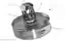
FIG. 1 shows a perspective view of a stopper head according to a preferred embodiment of the invention.
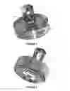
FIG. 2 shows another perspective view of the stopper head in FIG. 1.
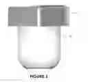
FIG. 3 shows a profile view of a stopper for a container obtained from the stopper head in FIG. 1.
FIGS. 1 and 2 show a stopper head according to a preferred embodiment of the invention. This stopper head 1, which is one piece, is made here from plastic.
This stopper head 1 is intended to be secured to a stopper body 2 to form a stopper for a container as shown in FIG. 3.
This head 1 comprises a base 3, forming a capsule, and a lug 4 protruding from this base 3. This lug 4, which is longitudinal, is designed to cooperate with the stopper body 2 during its overmolding around the lug.
The lug 4 comprises a single opening 5 that opens laterally through the lug such that the plastic can cross through the lug 4 during the overmolding of the stopper body 2 around it.
In addition, this opening 5 is clearly cone-shaped in the longitudinal direction of the lug 5, its base positioned on the side of the free end of the lug. Additional material support will therefore be present at this base, which is the part of the lug 4 that is the most highly stressed when removing the stopper from a bottle.
In addition, this stopper head 1 comprises stiffening ribs 6, 7 that are secured to the base 3 and to the lug 4. These ribs 6, 7, which are positioned on either side of the lug 4, are here straight ribs to block the rotation of the stopper body 2.
The stopper body 2 is advantageously made from a thermoplastic elastomer that is intended for food grade applications. Advantageously, this elastomer is loaded with particles of cork.
Claims
1-7. (canceled)
8. A stopper head intended to be fastened to a stopper body to form a stopper for a container, characterized in that:
said head comprises a base on which is situated a projecting tenon, said tenon being intended to cooperate with said body when assembling said body and said tenon, and
said tenon includes at least one opening discharging laterally at both ends in such a manner as to pass completely through said tenon to ensure anchoring of said body with said head, and in that
said tenon having an elongate shape, said opening has a shape flared in the longitudinal direction of said tenon, the widest part of said opening adjoining the free end of said tenon.
9. Head according to claim 8, characterized in that to prevent said body rotating about said tenon, said tenon has a shape that does not have symmetry of revolution.
10. Head according to claim 8, characterized in that said head comprises at least one member for mechanically reinforcing said tenon fastened on the one hand to said base and on the other hand to said tenon.
11. Head according to claim 10, characterized in that said at least one reinforcing member has a shape intended to cooperate with said body to prevent it from rotating.
12. Head according to claim 8, characterized in that said base includes on its face receiving said tenon attachment elements projecting from said base and/or a groove for reinforcing the adhesion of said body with said head.
13. Container stopper constituted of two different materials and including a stopper head (1) fastened to a body produced from a mouldable material or a combination of mouldable materials, characterized in that said stopper head (1) is a head according to claim 8.
14. Head according to claim 9, characterized in that said head comprises at least one member for mechanically reinforcing said tenon fastened on the one hand to said base and on the other hand to said tenon.
15. Head according to claim 9, characterized in that said base includes on its face receiving said tenon attachment elements projecting from said base and/or a groove for reinforcing the adhesion of said body with said head.
Images & Drawings included:
Sources:
- United States Patent and Trademark Office - verify current appl. status at the USPTO↗
Recent applications in this class:
- » 20230166890 2023-06-01
Method for manufacturing a closure for a product-retaining container - » 20220411136 2022-12-29
Tamper resistant reusable wine bottle stopper compatible with cork-screw-extractors - » 20220371784 2022-11-24
Cap for an opening of a container - » 20210139201 2021-05-13
Cap With Cork Insert - » 20190135500 2019-05-09
Method for manufacturing a closure for a product-retaining container - » 20190135499 2019-05-09
THERMOPLASTIC MATERIAL AND USE THEREOF IN THE PRODUCTION OF A CORK COMPOSITE MATERIAL - » 20180273252 2018-09-27
Closing element for containers and method for producing said closing element - » 20170341822 2017-11-30
DEVICE FOR SEALING A CONTAINER COMPRISING A NECK - » 20160297572 2016-10-13
STOPPER FOR CLOSING CONTAINERS - » 20140263453 2014-09-18
Vacuum bottle stopper for wine and method