LED light bar
US20120162977A1
2012-06-28
13/338,224
2011-12-27
✅ Patent granted
US 8,764,245 B2
2014-07-01
-
-
Bao Q Truong
2032-09-06
Abstract:
A LED light bar includes several LED light sources and a bar light source mounting base. The light source mounting base is made of an insulating and heat-conducting material. An electrical layer having several metal electricity-conducting plates is embedded in an inner part of the light source mounting base. The LED light sources are welded on the metal electricity-conducting plates to form an electrical electricity-conducting circuit. lighting sides of the LED light sources are exposed on a surface of the light source mounting base. The light source mounting base and the metal electricity-conducting plates are formed into a whole. Each LED light source is covered by lenses.
Inventors:
- Ming Chen 36 🇨🇳 Shanghai, China
- Yonghong Qiu 2 🇨🇳 Shanghai, China
- Liang Guo 3 🇨🇳 Shanghai, China
- Jiye Wu 1 🇨🇳 Shanghai, China
Assignee:
- Shanghai Sansi Electronics Engineering Co., Ltd 3 🇨🇳 Shanghai, China
- Shanghai Sansi Technology Co., Ltd. 27 🇨🇳 Shanghai, China
- Jiashan Sansi Photoelectric Technology Co., Ltd. 2 🇨🇳 Jiaxing, Zhejiang Province, China
Applicant:
Interested in similar patents?
Get notified when new applications in this technology area are published.
Classification:
F21V29/87 » CPC main
Protecting lighting devices from thermal damage; Cooling or heating arrangements specially adapted for lighting devices or systems characterised by the material Organic material, e.g. filled polymer composites; Thermo-conductive additives or coatings therefor
F21S4/28 » CPC further
Lighting devices or systems using a string or strip of light sources with light sources held by or within elongate supports rigid, e.g. LED bars
F21V29/507 » CPC further
Protecting lighting devices from thermal damage; Cooling or heating arrangements specially adapted for lighting devices or systems; Cooling arrangements characterised by the adaptation for cooling of specific components of means for protecting lighting devices from damage, e.g. housings
F21V29/74 » CPC further
Protecting lighting devices from thermal damage; Cooling or heating arrangements specially adapted for lighting devices or systems; Cooling arrangements characterised by passive heat-dissipating elements, e.g. heat-sinks with fins or blades
F21V5/007 » CPC further
Refractors for light sources Array of lenses or refractors for a cluster of light sources, e.g. for arrangement of multiple light sources in one plane
F21V31/00 » CPC further
Gas-tight or water-tight arrangements
F21Y2103/10 » CPC further
Elongate light sources, e.g. fluorescent tubes comprising a linear array of point-like light-generating elements
F21Y2115/10 » CPC further
Light-generating elements of semiconductor light sources Light-emitting diodes [LED]
H05K3/202 » CPC further
Apparatus or processes for manufacturing printed circuits in which conductive material is applied to the insulating support in such a manner as to form the desired conductive pattern by affixing prefabricated conductor pattern using self-supporting metal foil pattern
H05K3/202 » CPC further
Apparatus or processes for manufacturing printed circuits in which conductive material is applied to the insulating support in such a manner as to form the desired conductive pattern by affixing prefabricated conductor pattern using self-supporting metal foil pattern
H05K2201/10106 » CPC further
Indexing scheme relating to printed circuits covered by; Details of components or other objects attached to or integrated in a printed circuit board; Types of components Light emitting diode [LED]
H05K2201/10106 » CPC further
Indexing scheme relating to printed circuits covered by; Details of components or other objects attached to or integrated in a printed circuit board; Types of components Light emitting diode [LED]
F21V5/04 IPC
Refractors for light sources of lens shape
F21V29/00 IPC
Protecting lighting devices from thermal damage; Cooling or heating arrangements specially adapted for lighting devices or systems
Description
BACKGROUND OF THE PRESENT INVENTION
1. Field of Invention
The present invention relates to a field of LED lighting, and more particularly to a light bar of a LED lighting lamp having a high heat dissipating efficiency and a high protecting level.
2. Description of Related Arts
When a LED is used as a light source of a lighting lamp, main problems to be solved in designing are dissipating heats of the light source and waterproofness of the light lamps. For example, a conventional road lamp commonly has a front mask and a back cover to satisfy a requirement of dampproofness and waterproofness. However, such a structure condenses heats in a sealed space and causes unsatisfied heat dissipation results. The heavy structure also leads to a big weight and a big cost in materials of the whole lamp.
Besides, the conventional light source is installed integrally, which leads to great inconvenience in installing and maintaining, a low productive efficiency, a low level in scale and standardization.
According to a Chinese patent having an application number of 200920078033.2, a LED lighting lamp having a hollow structure is disclosed, which effectively solves the problems of heat dissipation and waterproofness to some extent. However, the LED light source is welded on a layer of circuit board, which adds a heat resistance to affect the heat dissipation to some degree. After the circuit board is put in a long slot, the slot is sealed through injecting glue. The glue body ages and falls apart with time so that insulation and waterproofness are affected.
SUMMARY OF THE PRESENT INVENTION
In order to solve problems mentioned above, the present invention provides a LED light bar having a good performance in dissipating heats, dampproofness and waterproofness, which is simply manufactured and used.
In order to realize the above purposes, the present invention adopts following technical solutions.
A LED light bar comprises several LED light sources and a bar light source mounting base. The light source mounting base is made of an insulating and heat conducting material. An electrical layer comprising several metal electricity-conducting plates is embedded in an inner part of the light source mounting base. The LED light sources are welded on the metal electricity-conducting plates to form an electrical electricity-conducting circuit. lighting sides of the LED light source are exposed on a surface of the light source mounting base. The light source mounting base and the metal electricity-conducting plates are formed into a whole. Each LED light source is covered by lenses.
A heat dissipating structure is provided on the light source mounting base.
The heat dissipating structure is provided on two sides of the light source mounting base.
The heat dissipating structure comprises a series of protuberances corresponding to each position of the LED light sources. The protuberances are hollow inside and have convex ribs on an outer wall thereof.
Heat dissipating plates are provided on a dark side of the light source mounting base.
The metal electricity-conducting plates are made of one material selected from the group consisting of gold, silver, copper, aluminum, aluminum alloy and copper alloy.
The LED light bar of the present invention has no circuit board for welding LED light sources and adopts metal electricity-conducting plates of highly heat-conducting which reduces the heat resistance and shortens heat-conducting paths to produce higher efficiency and better performance in dissipating heats. Moreover, the electrical electricity-conducting layer is provided in the inner part of the non-electricity-conducting light source mounting base. Thus results of effective dampproofness and waterproofness are realized without adopting other materials for sealing, and are free from limitations of service time and severe service environment. The light source mounting base and the central metal electricity-conducting plates are formed into a whole through plastic injection molding, which contributes to mass production and installation and effectively improves productive efficiency of lamps.
BRIEF DESCRIPTION OF THE DRAWINGS
Combined with drawings, further detailed description of technical solutions according to the present invention is following.
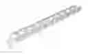
FIG. 1 is a sketch view of a structure of a light bar according to a preferred embodiment of the present invention.
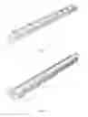
FIG. 2 is a sketch view of a dark side of the light bar shown in FIG. 1.
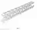
FIG. 3 is an exploded view of FIG. 1.
DETAILED DESCRIPTION OF THE PREFERRED EMBODIMENT
In FIG. 1, FIG. 2 and FIG. 3, according to a preferred embodiment of the present invention, a LED light bar is illustrated which comprising several LED light sources 1 and a bar light source mounting base 2. The light source mounting base 2 is made of insulating and heat-conducting materials. An electrical layer having several metal electricity-conducting plates is embedded in an inner part of the light source mounting base 2, wherein copper plates 3 of the metal electricity-conducting plates in the preferred embodiment have high heat-conducting coefficients. The light source mounting base 2 and the electrical layer comprising the copper plates 3 are formed into a whole through plastic injection molding. The several copper plates 3 are insulated connected with each other. Pins of positive electrodes and negative electrodes of the LED light sources 1 bridge among the copper plates connected with each other so as to form an electrical electricity-conducting circuit with the copper plates 3. Lighting sides of the LED light sources 1 are exposed on a surface of the light source mounting base 2 to maintain that lights from the LED light sources 1 are emitted out. Therefore, the lighting sides of the light source mounting base 2 have several holes opened thereon according to positions of the LED light sources 1 to install the LED light sources 1. In practical production, firstly the LED light sources 1 are placed at the locations for installing the LED light sources 1 on the molded LED light bar made through injecting plastic, and then the LED light sources 1 are welded through reflowing soldering. Finally lenses 4 are provided on each LED light source 1.
In the preferred embodiment of the present invention, a series of semi-ring protuberances 5 are provided at each position corresponding to each LED light source 1 on two sides of the light source mounting base 2 Inner sides of the protuberances 5 are in hollow shape and outer walls thereof are provided with a series of convex ribs 51. The hollow 50 allows heats dissipating through air convection. The convex ribs 51 enlarge a surface area of the light bar for dissipating heats so as to effectively improve efficiency in dissipating heats. A long slot 20 is provided at the back of the light source mounting base 2. A series of heat dissipation teeth in serration shapes are provided on walls of the long slot 20 to promote dissipating heats.
Claims
What is claimed is:1. A LED light bar, comprising several LED light sources and a bar light source mounting base, wherein said light source mounting base is made of an insulating and heat conducting material; an electrical layer comprising several metal electricity-conducting plates is embedded in an inner part of said light source mounting base; said LED light sources are welded on said metal electricity-conducting plates to form an electrical electricity-conducting circuit; lighting sides of said LED light sources are exposed on a surface of said light source mounting base which are formed with said metal electricity-conducting plates into a whole; lenses are provided and cover on each LED light source.
2. The LED light bar, as recited in claim 1, wherein a structure for dissipating heats is provided on said light source mounting base.
3. The LED light bar, as recited in claim 2, wherein said structure for dissipating heats are provided on two sides of said light source mounting base.
4. The LED light bar, as recited in claim 3, wherein said structure for dissipating heats comprises a series of protuberances which are provided at each position corresponding to each LED light source and hollow inside; convex ribs are provides on outer walls of said protuberances.
5. The LED light bar, as recited in claim 4, wherein heat dissipating plates are provided at a dark side of said light source mounting base.
6. The LED light bar, as recited in claim 1, wherein said metal electricity-conducting plates are made of one material selected from the group consisting of gold, silver, copper, aluminum, aluminum alloy and copper alloy.
Images & Drawings included:
Sources:
- United States Patent and Trademark Office - verify current appl. status at the USPTO↗
Similar patent applications:
- » 20130130520
Connector, PCB for LED light bar and LED light bar - » 20150204488
Method for manufacturing LED light bar and LED light bar thereof - » 20130272027
Method for Manufacturing LED Light Bar and LED Light Bar and Backlight Module - » 20160084456
Method for manufacturing LED light bar and LED light bar thereof - » 20190323697
Fluorescent glue for LED lighting bar and LED bulb lamp using the LED lighting bar - » 20170110443
LED light bar manufacturing method and LED light bar - » 20160320030
Apparatus for installing LED light bar and method of installing LED light bar - » 20140119000
LED light bar and backlight module using the LED light bar - » 20070206386
Integrated LED Light Bars and Roof Structure for Trailers - » 18956449
Light-emitting diode (LED) light bar and flexible neon lamp
Recent applications in this class:
- » 20230123362 2023-04-20
LED system without heat sink - » 20230083673 2023-03-16
Lamp assembly with thermal transporter - » 20220341582 2022-10-27
Composite luminaire - » 20200256554 2020-08-13
Lighting device, 3D-printed cooling element, and a method of producing a lighting device - » 20190093874 2019-03-28
In mold electronic printed circuit board encapsulation and assembly - » 20180363893 2018-12-20
THERMAL CONDUCTIVE FLEXIBLE PCB AND ALL PLASTIC HEAT SINK FOR LED BULB RETROFIT - » 20180252403 2018-09-06
Lamp assembly with thermal transporter - » 20180119941 2018-05-03
Plastic heat sink for luminaires - » 20170261195 2017-09-14
Lamp - » 20170211802 2017-07-27
Illumination apparatus utilizing conductive polymers
Recent applications for this Assignee:
- » 20250277571 2025-09-04
HIGHLY EFFICIENT HEAT DISSIPATION AUTOMOBILE LAMP - » 20250181300 2025-06-05
Modular display screen chassis and display scree - » 20250075878 2025-03-06
Reflective illumination structure and desk lamp - » 20240189471 2024-06-13
MULTI-BAND LED DISINFECTION SYSTEM AND MULTI-BAND LED DISINFECTION LAMP - » 20240165285 2024-05-23
DISINFECTION AND ILLUMINATION LAMP AND SYSTEM - » 20240142098 2024-05-02
Heat sink, separator, and lighting device applying same - » 20240050612 2024-02-15
LED PACKAGE STRUCTURE, AND DISINFECTION DEVICE AND DISINFECTION LAMP APPLYING SAME - » 20230126492 2023-04-27
LED UV sterilization device - » 20230007892 2023-01-12
LIGHT-EMITTING DEVICE - » 20230003351 2023-01-05
Multifunctional light source assembly and multifunctional desk lamp applying same