Process and device for the internal welding of plastic tubes
US20120164359A1
2012-06-28
13/385,628
2012-02-28
✅ Patent granted
US 8,329,270 B2
2012-12-11
-
-
N. Edwards
2032-02-28
Abstract:
The invention relates to a process for manufacturing plastic packaging in tubular form, which process comprises a wrapping step during which a laminate (11) is wrapped, an abutting step during which the edges (8, 9) of the laminate (11) are butted together and a fastening step during which said edges (8, 9) of the laminate (11) are welded together, characterized in that a bead (12) of plastic in the molten state is extruded and deposited on the internal face of the packaging so as to cover at least the weld zone (10) defined between the edges. The energy needed to produce the weld (10) comes from the plastic bead (12).
The invention also relates to packaging obtained from the aforementioned process and to a device for implementing said process.
Assignee:
- AISAPACK HOLDING S.A. 37 🇨🇭 Vouvry, Switzerland
Interested in similar patents?
Get notified when new applications in this technology area are published.
Classification:
B29C53/387 » CPC main
Shaping by bending, folding, twisting, straightening or flattening; Apparatus therefor; Bending and joining, e.g. for making hollow articles by bending sheets or strips at right angles to the longitudinal axis of the article being formed and joining the edges the joining being done from the inside
B29C53/382 » CPC further
Shaping by bending, folding, twisting, straightening or flattening; Apparatus therefor; Bending and joining, e.g. for making hollow articles by bending sheets or strips at right angles to the longitudinal axis of the article being formed and joining the edges using laminated sheets
B29C53/50 » CPC further
Shaping by bending, folding, twisting, straightening or flattening; Apparatus therefor; Bending and joining, e.g. for making hollow articles by bending sheets or strips at right angles to the longitudinal axis of the article being formed and joining the edges for articles of indefinite length, i.e. bending a strip progressively using internal forming surfaces, e.g. mandrels
B29C65/18 » CPC further
Joining of preformed parts ; Apparatus therefor by heating, with or without pressure using heated tools
B29C65/40 » CPC further
Joining of preformed parts ; Apparatus therefor by heating, with or without pressure Applying molten plastics, e.g. hot melt
B29C65/4815 » CPC further
Joining of preformed parts ; Apparatus therefor using adhesives, i.e. using supplementary joining material; solvent bonding characterised by the type of adhesives; Non-reactive adhesives, e.g. physically hardening adhesives Hot melt adhesives, e.g. thermoplastic adhesives
B29C65/72 » CPC further
Joining of preformed parts ; Apparatus therefor by combined operations or combined techniques , e.g. welding and stitching
B29C65/7894 » CPC further
Joining of preformed parts ; Apparatus therefor; Means for handling the parts to be joined, e.g. for making containers or hollow articles, e.g. means for handling sheets, plates, web-like materials, tubular articles, hollow articles or elements to be joined therewith; Means for discharging the joined articles from the joining apparatus characterised by the feeding movement of the parts to be joined; Means for handling of moving sheets or webs of continuously moving sheets or webs
B29C66/00441 » CPC further
General aspects of processes or apparatus for joining preformed parts; Preventing sticking together, e.g. of some areas of the parts to be joined of the joining tool and the parts to be joined using a separating sheet, e.g. fixed on the joining tool movable, e.g. mounted on reels
B29C66/1142 » CPC further
General aspects of processes or apparatus for joining preformed parts; General aspects dealing with the joint area or with the area to be joined; Particular design of joint configurations particular design of the joint cross-sections; Joint cross-sections comprising a single joint-segment, i.e. one of the parts to be joined comprising a single joint-segment in the joint cross-section; Single butt joints Single butt to butt joints
B29C66/4322 » CPC further
General aspects of processes or apparatus for joining preformed parts; General aspects of joining substantially flat articles, e.g. plates, sheets or web-like materials; Making flat seams in tubular or hollow articles; Joining single elements to substantially flat surfaces; Joining substantially flat articles ; Making flat seams in tubular or hollow articles; Joining a relatively small portion of the surface of said articles for making tubular articles or closed loops, e.g. by joining several sheets ; for making hollow articles or hollow preforms by joining a single sheet to itself
B29C66/49 » CPC further
General aspects of processes or apparatus for joining preformed parts; General aspects of joining substantially flat articles, e.g. plates, sheets or web-like materials; Making flat seams in tubular or hollow articles; Joining single elements to substantially flat surfaces Internally supporting the, e.g. tubular, article during joining
B29C66/723 » CPC further
General aspects of processes or apparatus for joining preformed parts characterised by the composition, physical properties or the structure of the material of the parts to be joined; Joining with non-plastics material characterised by the structure of the material of the parts to be joined being multi-layered
B29C66/83421 » CPC further
General aspects of processes or apparatus for joining preformed parts; General aspects of machine operations or constructions and parts thereof characterised by the movement of the joining or pressing tools moving with the parts to be joined; Roller, cylinder or drum types; Band or belt types; Ball types band or belt types
B29C66/836 » CPC further
General aspects of processes or apparatus for joining preformed parts; General aspects of machine operations or constructions and parts thereof characterised by the movement of the joining or pressing tools Moving relative to and tangentially to the parts to be joined, e.g. transversely to the displacement of the parts to be joined, e.g. using a X-Y table
B29C66/72321 » CPC further
General aspects of processes or apparatus for joining preformed parts characterised by the composition, physical properties or the structure of the material of the parts to be joined; Joining with non-plastics material characterised by the structure of the material of the parts to be joined being multi-layered comprising a non-plastics layer consisting of metals or their alloys
B29C66/7234 » CPC further
General aspects of processes or apparatus for joining preformed parts characterised by the composition, physical properties or the structure of the material of the parts to be joined; Joining with non-plastics material characterised by the structure of the material of the parts to be joined being multi-layered comprising a barrier layer
B29L2009/00 » CPC further
Layered products
B29L2023/00 » CPC further
Tubular articles
Y10T156/1013 » CPC further
Adhesive bonding and miscellaneous chemical manufacture; Methods of surface bonding and/or assembly therefor with permanent bending or reshaping or surface deformation of self sustaining lamina; Running or continuous length work; Longitudinal bending and edge-joining of one piece blank to form tube
Y10T428/1345 » CPC further
Stock material or miscellaneous articles; Hollow or container type article [e.g., tube, vase, etc.]; Nonself-supporting tubular film or bag [e.g., pouch, envelope, packet, etc.] Single layer [continuous layer]
Y10T428/1359 » CPC further
Stock material or miscellaneous articles; Hollow or container type article [e.g., tube, vase, etc.]; Polymer or resin containing [i.e., natural or synthetic]; Elemental metal containing [e.g., substrate, foil, film, coating, etc.] Three or more layers [continuous layer]
B29K2023/06 » CPC further
Use of polyalkenes or derivatives thereof as moulding material; Polymers of ethylene PE, i.e. polyethylene
B29C66/71 » CPC further
General aspects of processes or apparatus for joining preformed parts characterised by the composition, physical properties or the structure of the material of the parts to be joined; Joining with non-plastics material characterised by the composition of the plastics material of the parts to be joined
B29K2023/12 » CPC further
Use of polyalkenes or derivatives thereof as moulding material; Polymers of propylene PP, i.e. polypropylene
B65D65/40 IPC
Wrappers or flexible covers; Packaging materials of special type or form; Packaging materials of special type or form Applications of laminates for particular packaging purposes
B29C70/30 IPC
Shaping composites, i.e. plastics material comprising reinforcements, fillers or preformed parts, e.g. inserts comprising reinforcements only, e.g. self-reinforcing plastics; Shaping operations therefor Shaping by lay-up, i.e. applying fibres, tape or broadsheet on a mould, former or core; Shaping by spray-up, i.e. spraying of fibres on a mould, former or core
B32B1/08 IPC
Layered products having a general shape other than plane Tubular products
B65H69/02 IPC
Methods of, or devices for, interconnecting successive lengths of material; Knot-tying devices ;Control of the correct working of the interconnecting device by means of adhesives
B29C65/00 IPC
Joining of preformed parts ; Apparatus therefor
Description
FIELD OF THE INVENTION
The invention relates to the field of tubular packaging, especially consisting of a wrapped plastic laminate. More precisely, the invention relates to wrapped laminates, the edges of which do not overlap.
PRIOR ART
The welding of the edges of a laminate so as to obtain a tubular body usually takes place with an overlap. See for example German Patent Application DE 2008085.
When it is desired to place the edges face to face, a gap is left between them which is filled with a material, such as a strip of plastic, the strip acting as a welding element. See for this purpose European Patent Application EP 0 000 643.
However, there is a need to bring the edges into direct contact with each other (butt welding), for technical and aesthetic reasons. Butt welding provides better continuity and homogeneity of the material constituting the wall of the packaging. In particular, it avoids contact between the product placed inside the tube with a barrier layer placed inside the laminate. Moreover, the absence of a welding element on the external face reduces the visibility of the weld zone.
Moreover, whether the edges are placed end to end with or without a gap containing a welding element, there is also a need to be able to reduce, if not eliminate, the visibility of the weld from the outside of the tube.
The heating systems of the prior art are placed on the outside of the tube and their activation necessarily results in a pronounced and matt weld zone.
GENERAL DESCRIPTION OF THE INVENTION
The problem the present invention proposes to solve lies in the weakness of a butt weld and the maintaining of an attractive weld, i.e. one which is unnoticeable or almost unnoticeable when observed from the outside.
In the invention, the solution to the aforementioned problem consists in reinforcing such a weld by means of a bead of plastic.
The invention relates in the first place to a process for manufacturing plastic packaging in tubular form, which process comprises a wrapping step during which a laminate is wrapped, an abutting step during which the edges of the laminate are butted together and a fastening step during which said edges of the laminate are fastened together, characterized in that a bead of plastic in the molten state is extruded and deposited on the internal face of the packaging so as to cover at least the zone defined between the edges. One feature of the invention lies in the fact that the energy needed to produce the weld comes from the plastic bead.
According to a first variant of the process according to the invention, the bead is deposited prior to the abutting step.
According to a second variant, the bead is deposited during the abutting step.
According to a third variant, the bead is deposited after the abutting step.
The bead may be placed beneath or above the weld zone.
The invention also relates to tubular packaging obtained by the process as defined above, the packaging being characterized in that it comprises an element for reinforcing the zone defined between the edges, which consists of an extruded bead of plastic in the molten state.
Finally, the invention relates to a device for implementing a process as defined above. The device is characterized in that it includes a welding rod designed to be surrounded by a laminate, characterized in that it includes means for extruding and placing a bead of plastic in the molten state between the external surface of the welding rod and a laminate placed around said rod.
In one embodiment of the invention, the device includes a preheated conveyor belt placed on the welding rod so that said bead is placed between said belt and a laminate wrapped around said rod.
In another embodiment of the invention, the device includes an external drive belt and an adjustable bearing block that are placed so as to exert, in the direction of said rod, pressure on a laminate and a bead of plastic which would be placed between said drive belt and said rod.
Advantageously, a device may be used for preheating the edges, for example by contact, having the effect of increasing the temperature of the two edges of the laminate, thus facilitating or improving the welding conditions.
Alternatively, or in addition, another device is used which is provided with a hot-air blower so as to maintain the ambient air around the bead at a temperature of several hundred ° C. and consequently to avoid a drop in temperature of the bead as it passes from the exit of the extrusion head to the point where the bead is shaped.
According to one variant of the invention, the edges of the laminate are cut obliquely, this having the effect of increasing the lateral contact area of the laminate in the weld zone. Such a configuration also enables the quality and the strength of the weld to be influenced.
In another variant of the invention, a bead is extruded with a shape other than a cylinder, for example in the shape of an upside down T, thereby facilitating the shaping of the bead during welding.
Another variant of the invention consists in using a bead of coextruded plastic (coextruded with a barrier material at the centre of the bead) so as to also guarantee, in the zone defined between the edges of the laminate, good barrier protection from the external environment of the tube.
The present invention has several advantages, in particular:
-
- a complex high-frequency welding system is no longer necessary, the energy needed to produce the weld comes from the bead of plastic;
- the external appearance of the tube is perfect, given that the energy for producing the weld is applied from the inside. With the systems of the prior art, the energy is applied from the outside, the weld being matt and pronounced; and
- substantial covering layer (bead) made of PE or PP (or other materials) inside the tube along the join between the two edges of the laminate, preventing any contact between the product in the tube and the barrier layer (e.g. aluminium) of the laminate.
DETAILED DESCRIPTION OF THE INVENTION
The invention will be described in greater detail below by means of examples illustrated by the following figures:
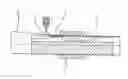
FIG. 1 is a perspective view of a first device according to the invention;
FIG. 2 is a lateral section of the device of FIG. 1;
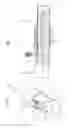
FIG. 3 is a perspective view of a second device according to the invention;
FIG. 4 is a lateral section of the device of FIG. 3;
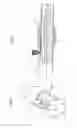
FIG. 5 is a perspective view of a third device according to the invention;
FIG. 6 is a lateral section of the device of FIG. 5;
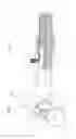
FIG. 7 is a perspective view of a fourth device according to the invention;
FIG. 8 is a lateral section of the device of FIG. 7;
FIG. 9 is a perspective view of a fifth device according to the invention;
FIG. 10 is a lateral section of the device of FIG. 9;
FIG. 11 shows a first variant of a weld according to the invention;
FIG. 12 shows a second variant of a weld according to the invention;
FIG. 13 shows a third variant of a weld according to the invention; and
FIG. 14 shows a fourth variant of a weld according to the invention.
LIST OF THE NUMERICAL REFERENCES USED IN THE FIGURES
1. Welding rod
2. Sizing die (height adjustable)
3. Internal belt (metallic)
4. Forming die
5. Bearing block
6. External belt
7. Extrusion head
8. First laminate edge
9. Second laminate edge
10. Weld zone
11. Laminate (continuous strip)
12. Bead of extruded plastic
13. Barrier layer
14. Gap
15. Compression wheel
16. Bead of coextruded plastic (coextruded with a barrier material at the centre of the bead).
The tube is formed continuously by progressively wrapping a strip of laminate 11 around the entire circumference of the welding rod 1, the laminate being pulled (from left to right in the figures) through the forming die 4. The laminate 11 made of PE or PP (or other materials) (whether a monolayer or a multilayer) is then welded longitudinally by depositing a bead 12 of extruded plastic in the molten state inside the tube.
Depending on the width of the laminate 11, it is possible to adjust the gap 14 between the edges 8, 9 of the laminate 11 formed on the final diameter of the tube. The bead 12 deposited inside may thus fill this gap 14 (FIG. 12) and also weld the outer layer of the laminate 11, e.g. a multilayer laminate that contains a barrier layer 13. If necessary, the weld 12 may even partly cover an external portion of the edges 8, 9 of the laminate 11 (FIG. 13). The use of a bead 12 of coextruded plastic in the molten state (coextruded with a barrier material 16 at the centre of the bead) also makes it possible to ensure that there is good barrier protection in the gap 14 from the external environment of the tube (FIG. 14). For aesthetic reasons, it is preferred to minimize this gap 14.
1st Variant:
FIGS. 1 and 2 illustrate the introduction of the bead 12, extruded in the molten state, by means of a preheated conveyor belt 3 onto a height-adjustable sizing die 2 after the cross section of the tube has been definitively formed by the laminate 11 in a die 4. The weld bead 12 is firstly applied against the inside of the preformed tube. The weld is then sized to the desired dimensions (top welding).
2nd Variant:
FIGS. 3 and 4 show the engagement of a bead 12, extruded in the molten state, by means of a preheated conveyor belt 3 onto a height-adjustable sizing die 2 before the cross section of the tube has been definitively formed by the laminate 11 in the die 4. Thus, the edges 8, 9 of the laminate 11, in its final shaping phase, are applied and pressed against the prepositioned bead 12 by means of an external drive belt 6 and an adjustable bearing block 5. The weld is therefore sized by prepositioning the bead 12, but in particular by the height adjustment of the bearing block 5.
3rd Variant:
FIGS. 5 and 6 show a similar principle, but reversed, this time with the welding from below. The bead 12, extruded in the molten state, is deposited directly inside the tube after its circular cross section has been definitively formed by the laminate 11 in the die 4. The weld is then pressed and sized by means of the internal belt 3 and the height-adjustable sizing die 2. In this variant, all the energy coming from the bead 12, needed to produce the weld, is transmitted directly to the laminate 11, thus minimizing energy losses by contact, for example, with the internal belt 3.
4th Variant:
FIGS. 7 and 8 show the engagement of the bead 12, extruded in the molten state, but tensioned, avoiding the bead being deposited on the conveyor belt 3. The energy losses are thus minimized as contact with the conveyor belt 3 is delayed as long as possible and takes place at the same time as the operation of shaping and compressing the bead 12.
5th Variant:
FIGS. 9 and 10 show the engagement of the bead 12, extruded in the molten state, but tensioned, the bead 12 being directly driven by the laminate 11 and no longer requiring a conveyor belt. The weld is then pressed and sized by a compression wheel 15 or, alternatively, by a compression block 2 (not illustrated).
Of course, the invention is not limited to the aforementioned examples.
Claims
1.-13. (canceled)
14. Tubular packaging obtained according to a process comprising:
a wrapping step during which a laminate, having edges, is wrapped,
an abutting step during which the edges of the laminate are butted together, and
a fastening step during which said edges of the laminate are welded together,
wherein a bead of plastic in a molten state is extruded and deposited on an internal face of the laminate so as to cover at least a weld zone defined between the edges,
wherein the energy needed to produce the weld coming from the plastic bead;
and wherein said packaging comprises an element for reinforcing the weld zone defined between the edges, which element consists of the extruded bead of plastic.
15. A device for manufacturing a tubular packaging as defined in claim 14, wherein the device includes means for extruding and placing a bead of plastic in the molten state between an external surface of a welding rod and a laminate wrapped around said rod.
16. A device according to claim 15, which further includes a preheated conveyor belt placed on the welding rod so that said bead is placed in the molten state between said conveyor belt and the laminate wrapped around said rod.
17. A device according to claim 15, which includes an external drive belt and an adjustable bearing block that are placed so as to exert, in the direction of said welding rod, pressure on a laminate and a bead of plastic in the molten state which would be placed between said drive belt and said welding rod.
18. A device according to claim 15, wherein said means for extruding and placing a bead of plastic in the molten state are placed on a same side as an upper face of the welding rod.
19. A device according to claim 15, wherein said means for extruding and placing a bead of plastic in the molten state are placed on a same side as a lower face of the welding rod.
20. A packaging made from the process comprising:
a wrapping step during which a laminate, having edges, is wrapped,
an abutting step during which the edges of the laminate are butted together, and
a fastening step during which said edges of the laminate are welded together,
wherein a bead of plastic in a molten state is extruded and deposited on an internal face of the laminate so as to cover at least a weld zone defined between the edges, the energy needed to produce the weld coming from the plastic bead, and
wherein the bead of plastic is extruded in the molten state onto a conveyor belt, and the molten bead of plastic contacts the internal face of the laminate prior to the abutting step.
21. A packaging according to claim 20, wherein the bead is placed in the molten state beneath said weld zone.
22. A packaging according to claim 20, wherein the bead consists of a plastic co-extruded with a barrier material at the centre of the bead.
Images & Drawings included:


Sources:
- United States Patent and Trademark Office - verify current appl. status at the USPTO↗
Recent applications in this class:
- » 20100000674 2010-01-07
Process for the internal welding of plastic tubes
Recent applications for this Assignee:
- » 20210291422 2021-09-23
Method for extruding and labelling a cylindrical product - » 20210187872 2021-06-24
Process for producing a packaging weld - » 20200070464 2020-03-05
Multilayer plastic tube structure - » 20200055220 2020-02-20
METHOD AND DEVICE FOR INJECTION OVERMOULDING - » 20190168318 2019-06-06
Rotary knife for machine for producing packaging and method using said knife - » 20170305685 2017-10-26
Method for orienting tube components - » 20170028608 2017-02-02
Method and device for the extrusion and labeling of a packaging tube - » 20160176106 2016-06-23
Indexing welding device for tube - » 20150132517 2015-05-14
Butt-welded tubular packaging body - » 20140309094 2014-10-16
Device and method for detecting and/or determining the position of a barrier layer contained in the wall of a tubular packaging material