Device For Discreet and Unobstructed Outdoor Observation
US20120167339A1
2012-07-05
12/981,341
2010-12-29
Abstract:
A device for discreet unobstructed outdoor observation can be attached to a window screen to allow for unobstructed viewing of the outdoors. Prior to attachment to the window screen, a portion of the window screen is cut away to expose a viewing area. The device is then positioned over the viewing area. A cap can be placed on the device when not in use. Preferably, a kit is provided including instructions, a template for cutting away a portion of the window screen at a desired location, and the viewing device.
Assignee:
- INNOVATIVE PRODUCTS OPERATIONS, INC. 1 🇺🇸 Apache Junction, AZ, United States
Interested in similar patents?
Get notified when new applications in this technology area are published.
Classification:
E06B9/24 » CPC main
Screening or protective devices for wall or similar openings, with or without operating or securing mechanisms; Closures of similar construction Screens or other constructions affording protection against light, especially against sunshine; Similar screens for privacy or appearance; Slat blinds
Y10T16/05 » CPC further
Miscellaneous hardware [e.g., bushing, carpet fastener, caster, door closer, panel hanger, attachable or adjunct handle, hinge, window sash balance, etc.] Bushing
Y10T29/49817 » CPC further
Metal working; Method of mechanical manufacture; Disassembling with other than ancillary treating or assembling
Y10T29/53004 » CPC further
Metal working; Means to assemble or disassemble with means to regulate operation by use of templet, tape, card or other replaceable information supply
E06B7/28 IPC
Special arrangements or measures in connection with doors or windows Other arrangements on doors or windows, e.g. door-plates, windows adapted to carry plants, hooks for window cleaners
B23P11/00 IPC
Connecting or disconnecting metal parts or objects by metal-working techniques not otherwise provided for
B23P17/00 IPC
Metal-working operations, not covered by a single other subclass or another group in this subclass
E06B7/16 IPC
Special arrangements or measures in connection with doors or windows Sealing arrangements on wings or parts co-operating with the wings
Description
FIELD OF THE INVENTION
The present invention relates to the field of viewing devices, and, more particularly, to a device for observing outdoor environments in a discreet manner.
BACKGROUND
It is often desirable to be able to view the outdoors without being observed. For example, one might own a country estate that is frequented by wildlife such as colorful birds and deer. While it is possible to peer out the window to view these creatures without disturbing them, often the window will have a screen which impedes viewing.
Furthermore, for security purposes, it may be necessary to discreetly observe objects and persons situated outside. There are devices on many doors allowing the homeowner to peer through the device to ensure that the door can be safely opened. A common device for such purposes is the peephole. In many cases, a peephole includes a wide angle lens. U.S. Pat. No. 4,869,021 to Gregory adds to the conventional peephole an opening wherein a telescope can be inserted. However, this device is only for a door, not a window, and the telescope can be seen from outside.
SUMMARY OF THE INVENTION
A device for discreet unobstructed outdoor observation can be attached to a window screen to allow for unobstructed viewing of the outdoors. Prior to attachment to the window screen, a portion of the window screen is cut away to expose a viewing area. The device is then positioned over the viewing area. A cap can be placed on the device when not in use. Preferably, a kit is provided including instructions, a template for cutting away a portion of the window screen at a desired location, and the viewing device.
According to preferred embodiments of the present invention, the device is structured and arranged to comprise a first ring, the first ring including a first threaded portion, and a second ring, the second ring including a second threaded portion. When the device is assembled and used, the first ring and the second ring are placed onto respective opposite sides of the window screen, and then threadably attached. Preferably, the first threaded portion and the second threaded portion are complementarily threaded, most preferably, the first threaded portion includes external threading and the second threaded portion includes complementary internal threading.
Preferably, the first ring further includes a cap retaining portion. Preferably, the viewing device further includes a cap, the cap attachable to the cap retaining portion.
In various preferred embodiments, the first ring further includes a mounting ring retaining portion. Preferably, a mounting ring is attachable to the mounting ring retaining portion. Preferably, the mounting ring includes a V-shaped mount to facilitate mounting of a camera, telescope, firearm, etc.
These and other aspects, features, and advantages of the present invention will become apparent from the following detailed description of preferred embodiments, which is to be read in connection with the accompanying drawings.
BRIEF DESCRIPTION OF THE DRAWINGS
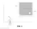
FIG. 1 shows an exemplary viewing device attached to a window screen for discreet unobstructed observation of the outdoors, according to preferred embodiments of the present invention;
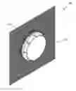
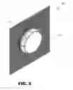
FIG. 2 shows a close-up perspective view of the viewing device;
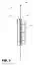
FIG. 3 shows a close-up side view of the viewing device;
FIG. 4 shows an exploded view of viewing device;
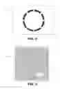
FIG. 5 shows an exemplary template for preparing a window screen for use of the viewing device, according to preferred embodiments of the present invention; and
FIG. 6 shows the exemplary template being used on an exemplary window screen.
DETAILED DESCRIPTION
FIG. 1 illustrates an exemplary viewing device 100 attached to a window screen 130 for discreet unobstructed observation of the outdoors. Preferably, and as shown, the exemplary viewing device 100 is circular; however, the viewing device 100 could, alternatively, be another shape, e.g., ovular, rectangular. As will be described in greater detail, preparatory to placement of the exemplary viewing device 100 onto the window screen 130, preferably, a portion of the window screen 130 corresponding in shape and size to the exemplary viewing device 100 is cut away. Then, the exemplary viewing device 100 is attached to the window screen 130, as shown.
When not in use, a cap 152 (shown in FIG. 2) can optionally be placed onto the viewing device 100. The exemplary viewing device 100 can be accessed whenever a user wants to discreetly observe the outdoors. By way of example, a user might wish to observe the outdoors using a telescope 160. In this case the user would simply remove the cap 152 (if it is on), position the telescope 160 to see through the viewing device 100, and then peer into the telescope 160 to obtain an unobstructed view of the outdoors. Alternately, the user could use another visual aid (such as binoculars) or just look out with the naked eye.
Referring to FIG. 3, a close-up side view of the exemplary viewing device 100 is shown. As depicted in FIG. 3, the exemplary viewing device 100 includes a first ring 156 and second ring 154 that are placed onto respective opposite surfaces of the window screen 130. The exemplary viewing device 100 is assembled upon the window screen 130 by screwing together the first ring 156 and the second ring 154, with the window screen 130 situated therebetween, as shown. Preferably, the first ring 156 includes a first threaded portion and the second ring 154 includes a second complementarily threaded portion. Also shown in FIG. 3 is a third ring 158 that acts, preferably, as a washer. On the inside surface of the window screen 130, preferably, the exemplary viewing device 100 includes the cap 152 which can be utilized when the device is not in use.
FIG. 4 shows an exploded view of the exemplary viewing device 100, according to a preferred embodiment of the present invention. As depicted, the first ring 156 includes an internally threaded portion 157 and the second ring 154 includes an externally threaded portion 159, the first ring 156 and the second ring 154 threadably attachable. As depicted, the second ring 159 also includes, on an opposite side thereof, a mounting ring retaining portion 151 and a cap retaining portion 153. A mounting ring 155 can be frictionally fitted into the mounting ring retaining portion 151. Preferably, the mounting ring 155 includes a V-shaped mount useable for mounting a camera, firearm, etc. The cap 152 can be attached to the cap retaining portion 152 by friction fitting it to the cap retaining portion 153.
Preferably, the viewing device 100 is made from a hard durable plastic such as Acrylonitrile Butadiene Styrene (ABS) or Polyvinyl Chloride (PVC). Preferably, the components of the present invention are each injection molded or produced using another suitable process. Preferably, the viewing device 100 will be available in various different sizes (e.g., 4-inch and 6-inch models). Preferably, the viewing device 100 will be produced in a solid color (e.g., gray, brown, black) to blend with the window screen. However, the viewing device 100 could also be made in various camouflage patterns and/or other colors.
FIG. 5 shows an exemplary template 175 for preparing the window screen 130 for use with the viewing device 100, according to a preferred embodiment of the present invention. FIG. 6 shows the exemplary template 175 being placed on the window screen 130. Preferably, the template 175 is made from a substantially flat, flexible material such as paper having a pressure-sensitive adhesive on a side thereof. In operation, the user presses the template 175 onto a desired area of the window screen 130 where the viewing device 100 will be placed. Then, the user uses a cutting instrument, such as a utility razor or an X-AXACTO knife, to carefully cut away a portion of the screen by following along the dashed line 172 with the cutting instrument. According to a preferred embodiment of the present invention, a kit is provided including a set of directions for applying the template 175 to the window screen 130 and assembling the viewing device 100 upon the window screen 100.
It is to be understood that the present invention is intended to be used solely for legal purposes. Furthermore, it is to be understood that nothing in the present disclosure is meant to encourage unlawful use (misuse) of the present invention.
While this invention has been described in conjunction with the various exemplary embodiments outlined above, it is evident that many alternatives, modifications and variations will be apparent to those skilled in the art. Accordingly, the exemplary embodiments of the invention, as set forth above, are intended to be illustrative, not limiting. Various changes may be made without departing from the spirit and scope of the invention.
Claims
What is claimed is:1. A viewing device for viewing the outdoors, comprising:
a first ring, the first ring including a first threaded portion; and
a second ring, the second ring including a second threaded portion;
wherein, when the viewing device is assembled and used on a prepared screen, the first ring and the second ring are placed onto respective opposite sides of the screen and threadably attached.
2. The viewing device of claim 1, wherein the first threaded portion and the second threaded portion are complementarily threaded.
3. The viewing device of claim 2, wherein the first threaded portion includes external threading and the second threaded portion includes internal threading.
4. The viewing device of claim 1, wherein the prepared screen is prepared by removing a portion of the screen.
5. The viewing device of claim 1, wherein the first ring further includes a cap retaining portion.
6. The viewing device of claim 5, further including a cap, the cap attachable to the cap retaining portion.
7. The viewing device of claim 1, further including a third ring, the third ring situate between the first ring and the second ring when the viewing device is assembled.
8. The viewing device of claim 7, wherein the third ring is a washer.
9. The viewing device of claim 1, wherein the first ring further includes a mounting ring retaining portion.
10. The viewing device of claim 7, further including a mounting ring, the mounting ring attachable to the mounting ring retaining portion.
11. The viewing device of claim 8, wherein the first ring is situate between the third ring and the mounting ring.
12. The viewing device of claim 8, wherein the mounting ring includes a V-shaped mount.
13. The viewing device of claim 1, wherein the first ring and the second ring are substantially circular.
14. The viewing device of claim 1, wherein the first ring and the second ring are substantially ovular.
15. The viewing device of claim 1, wherein the first ring and the second ring are substantially rectangular.
16. A kit for assembling a viewing device for viewing the outdoors, comprising:
a template comprising an adhesive-backed material having an outline thereupon;
the viewing device of claim 1; and
instructions for using the template to cut away a portion of the window screen to accommodate the viewing device and assembling the viewing device.
17. A method for installing a viewing device, comprising:
in accordance with the instructions provided in the kit of claim 16,
placing the template provided in the kit of claim 16 upon a window screen at a desired location;
following along the outline, cutting the window screen to form a viewing area; and
assembling the viewing device provided in the kit of claim 16 and placing it upon the window screen so that the viewing area is substantially unimpeded.
Images & Drawings included:

Sources:
- United States Patent and Trademark Office - verify current appl. status at the USPTO↗
Recent applications in this class:
- » 20250146355 2025-05-08
LIGHT-MODULATING ELECTROPHORETIC DEVICE - » 20250043623 2025-02-06
DUAL-MODE SMART SWITCHABLE LIQUID CRYSTAL WINDOW - » 20250043622 2025-02-06
FLEXIBLE LASER GLASS FILM STRUCTURE, GLASS AND WINDOW - » 20250020020 2025-01-16
Spring Assembly for A Multi-Stop Brake for Window Shades - » 20240401402 2024-12-05
CONNECTION ASSEMBLY WITH COMPOSITE PANEL AND RIBBON CABLE - » 20240401401 2024-12-05
Telescoping Window Cover System for Simultaneously Maintaining Privacy and Enabling Sunlight - » 20240352789 2024-10-24
COATED GLASS PANE - » 20240295144 2024-09-05
Light-modulating electrophoretic device - » 20240279983 2024-08-22
PRIVACY PROTECTION DEVICE - » 20240271483 2024-08-15
A WINDOW UNIT FOR A BUILDING OR STRUCTURE