Fluid flow channel and scavenger system
US20120168360A1
2012-07-05
12/930,218
2011-01-03
✅ Patent granted
US 8,584,403 B2
2013-11-19
-
-
Nam Nguyen | Richard Gurtowski
2031-10-28
Abstract:
A fluid flow channel includes a scavenging system to eject debris from the channel. The channel includes a back wall, channel floor, and upward ramp extending forward to an outer lip. The scavenging system includes a pivoted actuator with a face plate on a framework adapted for reciprocating rolling contact between retracted and forward positions relative to the back wall. The scavenging system rolls on tracks as it traverses the channel. The channel profile and scavenging system are configured to maximize the angle between face plate and ramp surface thereby minimizing the potential for jamming of the scavenging system during operation while economizing on channel width. The outer lip includes a flat top surface for transient support of the face plate framework at the end of its forward movement. The scavenging system further includes flexible wiper blades for sequential wiping contact with debris as it traverses the channel, and a forward-extending slider blade spring-biased toward the channel.
Inventors:
- Calvin A. Frelier 1 🇺🇸 Penfield, NY, United States
- Calvin A. Frelier 2 🇺🇸 Rochester, NY, United States
Applicant:
Interested in similar patents?
Get notified when new applications in this technology area are published.
Classification:
E04D13/0765 » CPC main
Special arrangements or devices in connection with roof coverings; Protection against birds ; Roof drainage; Sky-lights; Roof drainage; Drainage fittings in flat roofs, balconies or the like; Devices or arrangements for removing snow, ice or debris from gutters or for preventing accumulation thereof Cleaning tools
B08B9/00 » CPC further
Cleaning hollow articles by methods or apparatus specially adapted thereto
B01D21/30 IPC
Separation of suspended solid particles from liquids by sedimentation Control equipment
E04D13/00 IPC
Special arrangements or devices in connection with roof coverings; Protection against birds ; Roof drainage; Sky-lights
B01D29/00 IPC
Other filters with filtering elements stationary during filtration, e.g. pressure or suction filters, or filtering elements therefor
A47L13/02 IPC
Implements for cleaning floors, carpets, furniture, walls, or wall coverings Scraping
Description
BACKGROUND INFORMATION
Mechanically Actuated Self Cleaning Fluid Drainage System needs to be both commercially viable and robust in environments that contain heavy debris and grit accumulation associated with decaying roof drainage systems. For example, U.S. Pat. No. 7,610,721 issued Nov. 3, 2009 shows a device although suitable for roof drainage systems where the debris is light but it falls short of commercially viable solution where debris is heavier in nature. There is therefore a need for an improved Mechanically Actuated Self Cleaning Fluid Drainage System.
SUMMARY OF THE INVENTION
In summary, this invention is a combination fluid flow channel and scavenging system to eject debris from the channel. This combination is configured to minimize the potential for jamming and economize on overall width. The channel includes a back wall, channel floor, and upward ramp extending forward to an outer lip. The scavenging system includes a pivoted actuator with a face plate on a framework adapted for reciprocating rolling contact between retracted and forward positions relative to the back wall. The scavenging system rolls on tracks as it traverses the channel. The channel profile and scavenging system are configured to maximize the angle between face plate and ramp surface thereby minimizing the potential for jamming of the scavenging system during operation while economizing on channel width. The outer lip includes a flat top surface for transient support of the face plate framework at the end of its forward movement. The scavenging system further includes flexible wiper blades for sequential wiping contact with debris as it traverses the channel, and a forward-extending slider blade spring-biased toward the channel.
DRAWINGS
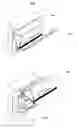
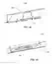
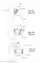
FIG. 1a is a left front perspective view of my fluid flow channel and scavenging system 100 in the park position while attached to a structure.
FIG. 1b is a left front perspective view of the fluid flow channel and scavenging system 100 in the open position while attached to a structure.
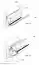
FIG. 2a is a left front perspective view of the fluid flow channel and scavenging system 100 in the park position.
FIG. 2b is an exploded view of with left front perspective of the channel and scavenging system 100.
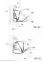
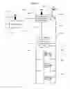
FIG. 2c is an end view of fluid flow channel 200
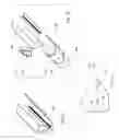
FIG. 3a is left rear perspective view of scavenging assembly 300.
FIG. 3b is an exploded left rear perspective view of scavenging assembly 300.
FIG. 3c is an exploded view of caster assembly 330.
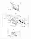
FIG. 4a is a rear perspective view of scavenging system 440.
FIG. 4b is a rear partial view of actuator 150 mounted to scavenger assembly 300 with actuator expanded.
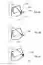
FIGS. 5a and 5b are end views of fluid flow channel 200 and scavenging system 100 depicting angular relationships.
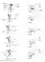
FIG. 6a through 6c are successive end views of fluid flow channel 200 and scavenging system 100 depicting interaction between scavenger system 440 and fluid flow channel 200.
FIG. 7a through 7e are successive end views showing interaction between flexible wiper 315 and fluid flow channel 200.
FIGS. 8a through 8e are successive end views showing the spatial relationship between scavenger system 440 and structure 7.
FIGS. 9a through 9c show prior art successive end views of the Gutter Drainage and Debris Removal System 10 (prior art U.S. Pat. No. 7,610,721).
FIG. 10 is a prior art block diagram showing remote control of the Gutter Drainage and Debris Removal System 10 (prior art U.S. Pat. No. 7,610,721).
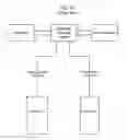
FIG. 11 is a block diagram showing centralized remote control for geographically separate installations of system 100.
DETAILED DESCRIPTION OF THE INVENTION
With reference now to the drawing figures: FIG. 1 show a combination fluid flow channel and scavenging system 100 (hereinafter referred to as system 100) mounted to structure 7 under the edge of a sloped roof surface with scavenger assembly 300 in the retracted or park position. System 100 allows fluid to flow along its length with the capability to expel accumulated solids in a direction roughly perpendicular to its length. Fluid flow systems tend to collect debris in the fluid flow channel; reliable function requires debris removal to promote drainage. FIG. 1b shows system 100 mounted to structure 7 with scavenger assembly 300 in the forward position after debris expulsion resting on fluid flow channel 200. It also shows actuator 150 (prior art defined in U.S. Pat. No. 7,610,721) attached to hinge clip 218 with a shaft (not shown).
FIG. 2a shows system 100 separate from supporting structure. FIG. 2b is an exploded view of system 100 that shows actuator 150 (prior art U.S. Pat. No. 7,610,721) pivotally connected to hinge clip 218 through pivot tab 154 using a shaft (not shown). Scavenger assembly 300 is fixed to actuator 150 to with fasteners. Spring loaded piano hinge 320 is fixed to the face of scavenger assembly 300 as shown in FIG. 2a by suitable fasteners. The piano hinge 320 is optional for heavy debris.
FIG. 2b shows wear plates 220 attached to fluid flow channel 200. Wear plates 220 are stainless steel 0.035″ thick, 4″ wide with a profile to match the interior surface of fluid flow channel 200. Wear plates 220 provide a running surface for scavenger assembly 300 as it traverses the profile of fluid flow channel 200. Wear plates 220 are located approximately 28.5″ from center, and suitably fixed to fluid flow channel 200. Fluid flow channel 200 is aluminum 0.05″ thick, 120″ in length, 3.8″ in height, and 6.8″ in width.
FIG. 2c shows features of fluid flow channel 200 as follows: registration edge 201 and registration surface 202, which together determine the vertical and horizontal location of hinge clip 218 and the pivot axis for actuator 150 as shown in FIG. 2b. Registration surface 202 is approximately 3″ tall. Material occlusion ramp 204 is angled to reduce debris buildup behind scavenger assembly 300. Channel floor 206 is 1.8″ across and supports scavenger assembly 300. Curved surface 208 is a transitional surface from channel floor 206 to ramp surface 210. Curved Surface 208 has a radius of 3.3″ and a sweep of 45°. Ramp surface 208 supports scavenger assembly 300 as debris is pushed out of fluid flow channel 200. Ramp surface 208 is approximately 2″ long. Ramp angle 212 is 45°. Top surface 210 is a resting surface for scavenger assembly 300. Stop surface 216 limits over travel of spring loaded piano hinge 320. Fluid flow channel 200 is secured to structure 7 (shown in FIG. 1a) by regularly spaced fasteners.
FIG. 3a shows scavenger assembly 300. FIG. 3b is an exploded view of scavenger assembly 300. It shows face plate framework 302 which consists of face plate 304, rear plates 306 and end caps 310. The overall length of face plate framework 302 is 118.5″. Face plate framework 302 provides the necessary rigidity to clear 10′ long sections of fluid flow channel 200 without buckling or twisting. Face plate framework 302 is approximately 4.4″ tall by 2.9″ wide. Rear plate 306 slopes at approximately a 30° angle. Face plate 304, rear plate 306, and end caps 310 are all constructed of 0.032″ thick aluminum and suitably joined to each other.
FIG. 3b also shows a spring loaded piano hinge 320 and caster assembly 330. Spring loaded piano hinge 320 includes mounting plate 322 and wiper plate 324. Mounting plate 322 is 0.05″ thick aluminum, and 118.5″ long by 1.5″ wide. Wiper plate 324 is 0.05″ thick aluminum, and 118.5″ in length and 1.5″ wide. Wiper plate 324 is joined to mounting plate 322 by stainless steel pins 0.125″ in diameter. Stainless steel torsion springs (not shown) provide approximately 2-3 inch-pound of torque total and bias wiper plate 324 against fluid flow channel 200. Spring loaded piano hinge 320 aids in evacuating debris that accumulates in fluid flow channel 200. Caster assembly 330 is suitably fixed to face plate framework 302 at a distance of approximately 28.5″ from center with fasteners. Castor assembly 330 aids in supporting scavenger assembly and reducing friction as it traverses fluid flow channel 200.
FIG. 3b also shows flexible wiper 315, which normally spans the entire length of scavenger assembly 300, except at caster assembly 330 locations. Flexible wiper 315 is fixed to face plate framework 302 using adhesive or fasteners. Flexible wiper 315 is fabricated in a continuous extrusion process and is made of EPDM Rubber with an approximate Shore A Durometer of 50. FIG. 7a shows wiper body 316, frontal blade 317, mid blade 318, and trailing blade 319. Flexible wiper 315 is approximately 0.86″ tall overall. Measured from wiper body 316, mid blade 318 is 0.35″ tall. Trailing blade 319 and frontal blade 317 are 0.31″ tall. Trailing blade 319 and frontal blade 317 are angularly separated from mid blade 318 by 35°. Mid blade 318, trailing blade 319, and frontal blade 317 are 0.07″ thick. Wiper body 316 is 0.28″ thick.
FIG. 3c is an exploded view of caster assembly 330. Caster assembly 330 is comprised of caster bracket 332, roller 334, shoulder screw 336, and lock Nut 338. Caster bracket 332 is 0.075″ thick stainless steel with a height and width of 1.4″. Roller 334 is nylon with a diameter of 0.75″ and a width of 0.48″. Shoulder screw 336 is McMaster-Carr part number 94035A532. Lock nut 338 is McMaster-Carr part number 90101A225.
FIG. 4a shows scavenging system 440 consisting of actuator 150 mounted to scavenger assembly 300 while viewing the rear side of scavenger assembly 300.
FIG. 4b is a partial view of actuator 150 mounted to scavenger assembly 300 with actuator 150 expanded. In FIG. 4b orbital shaft (prior art not shown) defined in U.S. Pat. No. 7,610,721, is replaced by lock nut 338, shoulder screw (not shown), and roller (not shown) in an arrangement similar to caster assembly 330 shown in FIG. 3c.
FIGS. 5a and 5b show resistance angle 510 as the angle created by a line originating at the hinge axis of hinge clip 218 and ending at the intersection of roller 334 and wear plate 220 and the tangent of roller 334 and wear plate 220. The cosine of angle 510 yields the fraction of actuator force available to overcome rolling resistance at the interface of roller 334 and wear plate 220. As angle 510 increases, the system requires more air pressure to operate. FIG. 5a shows a resistance angle 510 which is approximately 67°.
FIG. 5a shows parking angle 520 as the angle between face plate 304 of scavenger assembly 300 and wear plate 220. When parking angle 520 is less than approximately 78°, system 100 will remain in its retracted or park position without air pressure. As parking angle 520 decreases, resistance angle 510 increases.
FIG. 5b shows pinch angle 500 which is defined as the angle between face plate 304 and ramped surface 210 (FIG. 2c).
FIGS. 6a, 6b, and 6c sequentially show the interaction between spring loaded piano hinge 320, ramped surface 210, top surface 214, and striker surface 216.
FIGS. 7a-7e sequentially show the rotational interaction between flexible wiper 315 and the profile of fluid flow channel 200 as scavenger system 440 traverses during scavenging.
FIGS. 8a-8e sequentially show the spatial interaction between scavenger system 440 and structure 7.
FIG. 9a is prior art that shows gutter section 14 mounted on support structure 7, drip edge 19, scavenger blade 16, and wiper 13, in the park position.
FIG. 9b is prior art that shows drip edge 19, scavenger blade 16, gutter section 14, and pinch angle 500.
FIG. 9c is prior art that shows drip edge 19, scavenger blade 16, gutter section 14, wiper 13 and gap 517 in the forward position.
FIG. 10 is a prior art block diagram that shows co-located electrically actuated valves.
FIG. 11 is a block diagram which shows scavenger systems 440 connected in parallel with air line open 820 (line 820) and air line close 822 (line 822). Pneumatic solenoid valve 810 controls lines 820 and 822. Pressurization of line 820 causes scavenger system 440 to move to the forward position as shown in FIG. 1b. Pressurization of line 822 causes scavenger system 440 to retract to park position as shown in FIG. 1a. As either line 822 or 820 are pressurized, air in the other line is exhausted through a port in pneumatic solenoid valve 810. Compressed air line 808 conveys pressurized air from air compressor 806 to pneumatic solenoid valve 810. 24V line 818 transmits control power from programmable logic controller and power supply (PLC) 826 to pneumatic solenoid valve 810. Programmable logic controller and power supply 826 controls air compressor 806 through control line 824 and receives air compressor 806 feedback through logical signal and telemetry line 812. Control panel 800 contains circuitry necessary to signal PLC 826 to initiate scavenging routines, and control panel 800 can communicate through a logical signal and telemetry line 812 or by wireless receiver and transmitter 816 with PLC 826.
Operational Description of the Invention
Wear plates 220 (FIG. 2b) provide lower contact friction for spring loaded piano hinge 320 (FIG. 3b) because the coefficient of friction between aluminum and stainless steel is less than aluminum against aluminum. Wear plates 220 are also rolling interface for roller 334 (FIG. 3c) and eliminate wear on fluid flow channel 200.
FIG. 3b shows face plate framework 302, by comparison (prior art) FIG. 9b shows scavenging blade 16 (U.S. Pat. No. 7,610,721) in profile. Face plate framework 302 is fashioned with enclosed box structures that have higher strength to weight ratios compared to an open channel construction of scavenging blade 16. The increased rigidity and strength of face plate framework 302 is needed to remove heavier debris from fluid flow channel 200.
FIG. 5b shows pinch angle 500 at approximately 44°. Pinch angle 500 implies the likelihood of scavenging difficulty. As the pinch angle becomes smaller, it is harder to expel solids during scavenging. FIG. 9b (prior art) shows a smaller pinch angle 500 of 22° for a similar position in the scavenging cycle.
FIGS. 6a, 6b, and 6c show how spring loaded piano hinge 320 enhances the debris ejection process. As wiper plate 324 pivots about top surface 214, torque supplied by torsion springs in spring loaded piano hinge 320 accelerates the debris ejection process. Stop surface 216 limits rotational over travel of spring loaded piano hinge 320.
FIGS. 7a, 7b, 7c, 7d, and 7e illustrate how flexible wiper 315 interacts with fluid flow channel 200 during scavenging to remove small debris from fluid conveyance channel 200. As flexible wiper 315 advances during scavenging it experiences counter clockwise rotation relative to fluid flow channel. By consecutively exposing debris to additional wipers, this aids in removal of small debris. By comparison, prior art FIGS. 9a-9c show a wiper 13 with a continuous surface.
FIGS. 8a, 8b, 8c, 8d, and 8e illustrate how the gap between drip edge 19 and upper lip 312 is minimized throughout the scavenging cycle; this minimizes the opportunity for debris to fall behind the scavenging blade assembly 300 during a scavenging cycle. FIG. 9c (prior art) shows a larger gap 527. This improvement results from the choice of fluid flow channel 200 profile and scavenger system 440 pivot axis location.
Prior art shown FIG. 10 box diagram shows a co-location of all electrically actuated (pneumatic solenoid) valves. This prior art diagram and description (see column 4 line 26 of U.S. Pat. No. 7,610,721) describe a bank of centrally located electrically actuated valves with pneumatic (air) lines 32 and 34 running to systems 10. Because lines 32 and 34 must be alternately pressurized and vented during operation, the need for compressed air increases as lines 32 and 34 grow in length and internal diameter. This approach is sufficient for smaller buildings and houses.
FIG. 11 shows a relocated pneumatic solenoid valve 810 from a central bank to a branch location near each dependant series of scavenging systems 440. By lengthening compressed air line 808 and shortening air lines 820 and 822, the performance of scavenging system 440 is improved and the amount of compressed air needed per cycle is reduced. This improvement allows system 100 to be more easily employed on large homes and buildings.
FIG. 11 also shows a remote control panel which by virtue of wires 812 or wireless 816 communications permits central control 800 over separate system 100 installations on geographically separate buildings. Prior art FIG. 10 describes remote control of individual or groups of actuators within a single structure. By contrast FIG. 11 describes a means to remotely control entire installations of systems 100 located on separate structures in different geographical locations.
The foregoing description of a preferred embodiment of the invention, including dimensions, is illustrative. The concept and scope of the invention are not limited by details of the description but only by the following claims.
| PARTS LIST |
| Number | Name | FIG. |
| 7 | Structure | 1a, 1b, 5a, 6a |
| 10 | Gutter Drainage and Debris Removal | 9a |
| System (prior art) | ||
| 13 | Wiper (prior art) | 9c |
| 14 | Gutter Section (prior art) | 9a-9c |
| 16 | Scavenging Blade (prior art) | 9a-9c |
| 19 | Drip Edge | 8a-8e, 9a-9c |
| 32 | Pneumatic Line (prior art) | 10 |
| 34 | Pneumatic Air Line (prior art) | 10 |
| 100 | Combination Fluid Flow Channel and | 1a, 1b, 2a, 2b |
| Scavenging System | ||
| 150 | Actuator defined in U.S. Pat. No. | 1b, 2b, 4a, 4b |
| 7,610,721 | ||
| 154 | Pivot Tab | 2b |
| 200 | Fluid Flow Channel | 1a, 1b, 2b |
| 201 | Registration Edge | 2c |
| 202 | Registration Surface | 2c |
| 204 | Material Occlusion Ramp | 2c |
| 206 | Channel Floor | 2c |
| 208 | Curved Surface | 2c |
| 210 | Ramp Surface | 2c |
| 212 | Ramp Angle | 2c |
| 214 | Top Surface | 2c |
| 216 | Stop Surface | 2c |
| 218 | Hinge Clip | 2b, 5a, 5b |
| 220 | Wear Plate | 2b, 5a, 5b |
| 300 | Scavenger Assembly | 1a, 1b, 2b, 3a, 3b, 5a, 8a |
| 302 | Face Plate Framework | 3b |
| 304 | Face Plate | 3b |
| 306 | Rear Plate | 3b |
| 310 | End Cap | 3b |
| 312 | Upper Lip | 8a-8d |
| 315 | Flexible Wiper | 3b, 7a-7e |
| 316 | Wiper Body | 7a |
| 317 | Frontal Blade | 7a-7e |
| 318 | Mid Blade | 7a-7e |
| 319 | Trailing Blade | 7a, 7e |
| 320 | Spring Loaded Piano Hinge | 2b, 3b, 6a |
| 322 | Mounting Plate | 3b |
| 324 | Wiper Plate | 3b, 6a-6c |
| 330 | Caster Assembly | 3b, 3c |
| 332 | Caster Bracket | 3c |
| 334 | Roller | 3c, 5a |
| 336 | Shoulder Screw | 3c |
| 338 | Lock Nut | 3c, 4b |
| 440 | Scavenger System | 4a |
| 500 | Pinch Angle | 5b, 9b |
| 510 | Resistance Angle | 5a, 5b |
| 520 | Parking Angle | 5a |
| 527 | Gap | 9c |
| 800 | Control Panel | 11 |
| 806 | Air Compressor | 11 |
| 808 | Compressed Air Line | 11 |
| 810 | Pneumatic Solenoid Valve | 11 |
| 812 | Logical Signal and Telemetry Line | 11 |
| 816 | Wireless Receiver and Transmitter | 11 |
| 818 | 24 Volt Line | 11 |
| 820 | Air Line Open | 11 |
| 822 | Air Line Close | 11 |
| 824 | Compressor Power Control Line | 11 |
| 826 | Programmable Logic Controller and | 11 |
| Power Supply | ||
Claims
1. A combination fluid flow channel and scavenging system to eject debris from said channel;
said channel including a back wall and a channel portion with an upward-sloped ramp surface extending forward of said back wall to an outer lip;
said scavenging system including an actuator pivotally mounted on a pivot axis parallel to said channel and reciprocally expansible between retracted and forward positions relative to said back wall, and a face plate mounted on said actuator and adapted for rolling contact with said channel as it traverses said channel;
said ramp surface of said channel configured to maximize the angle of said face plate relative to said ramp surface as said face plate traverses said channel, thereby to economize channel width and minimize the potential for jamming of said scavenging system;
said outer lip including a flat top surface for transient support of said face plate at the end point of forward movement thereof;
said scavenging system further including a flexible wiper depending from said face plate into proximity with said channel to wipe debris from said channel as said wiper traverses said channel.
2. A combination fluid flow channel and scavenging system to eject debris from said channel;
said channel including a back wall and a channel portion with an upward-sloped ramp surface extending forward of said back wall to an outer lip;
said scavenging system including an actuator pivotally mounted on a pivot axis parallel to said channel and reciprocally expansible between retracted and forward positions relative to said back wall, and a face plate framework mounted on said actuator and adapted for rolling contact with said channel as it traverses said channel, said face plate framework including a face plate;
said ramp surface of said channel configured to maximize the instantaneous angle of said face plate relative to said ramp surface as said face plate framework traverses said channel, thereby to economize, channel width and minimize the potential for jamming of said scavenging system;
said outer lip including a flat top surface for transient support of said face plate framework at the end point of forward movement thereof;
said scavenging system further including a flexible wiper depending from said face plate framework into proximity with said channel to wipe debris from said channel as said wiper traverses said channel.
3. The combination defined in claim 2;
said flexible wiper including a plurality of depending flexible wiper blades angled from each other for sequential wiping of said channel as said wiper traverses said channel.
4. The combination defined in claim 2;
said scavenging system further including a forward-extending slider blade pivotally mounted on said face plate framework and spring-biased downward toward said channel;
said outer lip further including a depending flange to prevent over travel of said slider blade at the end of forward movement thereof;
5. The combination defined in claim 2;
said channel further including a plurality of parallel roller tracks spaced along said channel, each said roller track extending forward of said back wall, across said channel portion, and onto said outer lip for supporting engagement with rollers on said face plate framework.
6. The combination defined in claim 2;
said actuator including a pneumatic expansible chamber device;
said scavenging system further including a solenoid operated pneumatic valve adjacent to said pneumatic expansible chamber device and pneumatically connected thereto; and a control system, remote from said pneumatic valve, operatively connected to said pneumatic valve.
7. A control system for central control of a plurality of independent channel scavenging systems, said control system being remote from said scavenging systems.
Images & Drawings included:
Sources:
- United States Patent and Trademark Office - verify current appl. status at the USPTO↗
Recent applications in this class:
- » 20240401337 2024-12-05
Gutter and downspout cleaning device and method - » 20240279933 2024-08-22
VEHICLE CONTROL DEVICE FOR DRIVER AND VEHICLE CONTROL METHOD FOR DRIVER - » 20230101067 2023-03-30
PRESSURE SPRAY WASHER FOR CLEANING GUTTERS - » 20230048121 2023-02-16
Device for cleaning gutters - » 20230008849 2023-01-12
SELF-CLEANING AND SMART GUTTER SYSTEM - » 20220235554 2022-07-28
COUPLINGS FOR TUBING - » 20220220743 2022-07-14
Apparatus for cleaning gutters and methods of use - » 20210262236 2021-08-26
Gutter cleaners and methods associated therewith - » 20210254344 2021-08-19
Gutter cleaners and methods associated therewith - » 20200392737 2020-12-17
GUTTER CLEANER AND A BUCKET HANGER