HOSE REEL SPRING ADJUSTMENT
US20120168549A1
2012-07-05
13/394,937
2010-10-27
Abstract:
An enclosed hose reel 10 consists of a spool and two enclosure halves 14 comprising the frame 16. The power spring 18 is contained in the spool 12. Tension on the power spring 18 is transmitted to the frame 16 via a shaft 20 with a spring 30 loaded ratchet 22. The ratchet mechanism 24 engages the frame 16 via protrusions 26 that fit into cutouts 28 within the enclosure 14. The protrusions and cutouts 28 are designed so that a clockwise rotation is allowed to increase the tension of the power spring 18.
Inventors:
- Mark L. Bauck 22 🇺🇸 Coon Rapids, MN, United States
- Zaixing You 2 🇨🇳 Phoenix City, China
- Lihui Gao 2 🇨🇳 PingJiang District, China
- Xueshui Wu 2 🇨🇳 Phoenix City, China
- Jin Tian 2 🇨🇳 Can Lang Borough, China
- Thomas R. Larson 1 🇺🇸 Elk River, MN, United States
Interested in similar patents?
Get notified when new applications in this technology area are published.
Classification:
B65H75/486 » CPC main
Storing webs, tapes, or filamentary material, e.g. on reels; Cores, formers, supports, or holders for coiled, wound, or folded material, e.g. reels, spindles, bobbins, cop tubes, cans, mandrels or chucks specially adapted or mounted for storing and repeatedly paying-out and re-storing lengths of material provided for particular purposes, e.g. anchored hoses, power cables involving the use of a core or former internal to, and supporting, a stored package of material; Constructional details; Automatic re-storing devices Arrangements or adaptations of the spring motor
B65H2701/33 » CPC further
Handled material; Storage means; Handled filamentary material Hollow or hose-like material
B65H75/48 IPC
Storing webs, tapes, or filamentary material, e.g. on reels; Cores, formers, supports, or holders for coiled, wound, or folded material, e.g. reels, spindles, bobbins, cop tubes, cans, mandrels or chucks specially adapted or mounted for storing and repeatedly paying-out and re-storing lengths of material provided for particular purposes, e.g. anchored hoses, power cables involving the use of a core or former internal to, and supporting, a stored package of material; Constructional details Automatic re-storing devices
Description
TECHNICAL FIELD
This application claims the benefit of U.S. application Ser. No. 61/256,224, filed Oct. 29, 2009, the contents of which are hereby incorporated by reference.
BACKGROUND ART
Spring loaded hose reels for retractably storing air and fluid hoses are of course well known. Prior art designs require maintaining torque on the hub with a wrench while removing and replacing the required fasteners.
DISCLOSURE OF THE INVENTION
An enclosed hose reel consists of a spool and two enclosure halves comprising the frame. The power spring is contained in the spool. Tension on the power spring is transmitted to the frame via a shaft with a spring loaded ratchet. The ratchet mechanism engages the frame via protrusions that fit into cutouts within the enclosure. The protrusions and cutouts are designed so that a clockwise rotation is allowed to increase the tension of the power spring. The ratchet is spring loaded to allow for axial movement of the ratchet to step to the next clockwise position of the ratchet. The ratchet has an externally exposed hex shape and an internal square drive socket. To increase the spring tension the user simply turns the ratchet in the clockwise direction using a wrench or a socket wrench. To decrease the spring tension the user must apply torque to the wrench or socket wrench, push the ratchet in and then turn the ratchet counterclockwise while allowing the ratchet to move outward to engage the next counterclockwise position.
This invention enables one handed hose reel spring adjustment and allows for a safer method of hose reel spring adjustment.
These and other objects and advantages of the invention will appear more fully from the following description made in conjunction with the accompanying drawings wherein like reference characters refer to the same or similar parts throughout the several views.
BRIEF DESCRIPTION OF DRAWINGS
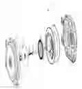
FIG. 1 shows an exploded view of a hose reel utilizing the instant invention.
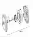
FIG. 2 shows a partial exploded view of a hose reel utilizing the instant invention with the ratchet flipped 180 degrees for clarity.
BEST MODE FOR CARRYING OUT THE INVENTION
An enclosed hose reel 10 consists of a spool 12 and two enclosure halves 14 comprising the frame 16. The power spring 18 is contained in the spool 12. Tension on the power spring 18 is transmitted to the frame 16 via a shaft 20 with a spring 30 loaded ratchet 22. The ratchet mechanism 24 engages the frame 16 via protrusions 26 that fit into cutouts 28 within the enclosure 14 . The protrusions 26 and cutouts 28 are designed so that a clockwise rotation is allowed to increase the tension of the power spring 18. The ratchet 22 is spring 30 loaded to allow for axial movement of the ratchet 22 to step to the next clockwise position of the ratchet 22. The ratchet 22 has an externally exposed hex shape 32 and an internal square drive socket 34.
To increase the spring tension the user simply turns the ratchet 22 in the clockwise direction using a wrench or a socket wrench. To decrease the spring tension the user must apply torque to the wrench or socket wrench, push the ratchet 22 in and then turn the ratchet 22 counterclockwise while allowing the ratchet 22 to move outward to engage the next counterclockwise position.
It is contemplated that various changes and modifications may be made to the hose reel without departing from the spirit and scope of the invention as defined by the following claims.
Claims
1. A hose reel comprising:
a spool;
first and second enclosure halves forming a frame;
a power spring contained in said spool;
a shaft; and
a spring loaded ratchet whereby tension on said power spring is transmitted to said frame via said ratchet, said ratchet comprising a plurality of protrusions and said enclosure comprising a plurality of cutouts, said ratchet engaging said frame with said protrusions that fit into said cutouts within said enclosure.
2. The hose reel of claim 1 wherein said ratchet is spring loaded to allow for axial movement of said ratchet on said shaft.
3. The hose reel of claim 1 wherein said ratchet has an externally exposed hex shape and an internal square drive socket.
Images & Drawings included:
Sources:
- United States Patent and Trademark Office - verify current appl. status at the USPTO↗
Recent applications in this class:
- » 20240300778 2024-09-12
Tape Measure with Epicyclic Gear Drive for Tape Retraction - » 20230011558 2023-01-12
WINDING DRUM AND TORSION SPRING FOR A WINDING DRUM - » 20220363510 2022-11-17
Tape measure with epicyclic gear drive for tape retraction - » 20220306425 2022-09-29
DOUBLE DRAWCORD WINDING DEVICE - » 20220127106 2022-04-28
FLEXIBLE DISPLAY DEVICE AND TORSION SPRING USED THEREIN - » 20220017325 2022-01-20
Lanyard with locking arm - » 20210387828 2021-12-16
Cable adjuster - » 20210114840 2021-04-22
RETRACTABLE STRAP - » 20210070585 2021-03-11
Tape measure with epicyclic gear drive for tape retraction - » 20200223657 2020-07-16
Automatic Winding Device