Lighting device
US20120169201A1
2012-07-05
13/095,709
2011-04-27
✅ Patent granted
US 8,334,641 B2
2012-12-18
-
-
Mariceli Santiago | Donald Raleigh
2031-04-27
Abstract:
A lighting device includes a bottom housing, a middle housing, a top housing, and a lamp head. Specifically, the bottom housing has a bottom surface capable of supporting a lighting module. The middle housing is coupled to the top side of the bottom housing. The top housing is coupled to the top side of the middle housing, such that the middle housing is disposed between the bottom housing and the top housing. The lamp head covers the sidewall of the top housing.
Assignee:
- Top Energy Saving System Corp. 6 🇹🇼 New Taipei City, Taiwan
- Top Energy Saving System Corp. 3 🇹🇼 New Taipei, Taiwan
Interested in similar patents?
Get notified when new applications in this technology area are published.
Classification:
F21V29/83 » CPC main
Protecting lighting devices from thermal damage; Cooling or heating arrangements specially adapted for lighting devices or systems; Cooling arrangements characterised by passive heat-dissipating elements, e.g. heat-sinks the elements having apertures, ducts or channels, e.g. heat radiation holes
F21K9/232 » CPC further
Light sources using semiconductor devices as light-generating elements, e.g. using light-emitting diodes [LED] or lasers; Light sources comprising attachment means; Retrofit light sources for lighting devices with a single fitting for each light source, e.g. for substitution of incandescent lamps with bayonet or threaded fittings specially adapted for generating an essentially omnidirectional light distribution, e.g. with a glass bulb
F21V29/74 » CPC further
Protecting lighting devices from thermal damage; Cooling or heating arrangements specially adapted for lighting devices or systems; Cooling arrangements characterised by passive heat-dissipating elements, e.g. heat-sinks with fins or blades
F21V3/00 » CPC further
Globes; Bowls; Cover glasses
F21V29/507 » CPC further
Protecting lighting devices from thermal damage; Cooling or heating arrangements specially adapted for lighting devices or systems; Cooling arrangements characterised by the adaptation for cooling of specific components of means for protecting lighting devices from damage, e.g. housings
F21V29/86 » CPC further
Protecting lighting devices from thermal damage; Cooling or heating arrangements specially adapted for lighting devices or systems characterised by the material Ceramics or glass
F21V29/89 » CPC further
Protecting lighting devices from thermal damage; Cooling or heating arrangements specially adapted for lighting devices or systems characterised by the material Metals
F21Y2105/10 » CPC further
comprising a two-dimensional array of point-like light-generating elements
F21Y2115/10 » CPC further
Light-generating elements of semiconductor light sources Light-emitting diodes [LED]
H01J61/52 IPC
Gas-discharge or vapour-discharge lamps; Details Cooling arrangements; Heating arrangements; Means for circulating gas or vapour within the discharge space
H01J1/62 IPC
Details of electrodes, of magnetic control means, of screens, or of the mounting or spacing thereof, common to two or more basic types of discharge tubes or lamps; Screens on or from which an image or pattern is formed, picked-up, converted, or stored; Luminescent coatings on vessels Luminescent screens; Selection of materials for luminescent coatings on vessels
H01J5/00 IPC
Details relating to vessels or to leading-in conductors common to two or more basic types of discharge tubes or lamps
H01J1/02 IPC
Details of electrodes, of magnetic control means, of screens, or of the mounting or spacing thereof, common to two or more basic types of discharge tubes or lamps Main electrodes
Description
CROSS-REFERENCE TO RELATED APPLICATIONS
The entire contents of Taiwan Patent Application No. 100200061, filed on Jan. 4, 2011, from which this application claims priority, are incorporated herein by reference.
BACKGROUND OF THE INVENTION
1. Field of the Invention
The present invention generally relates to a lighting device, and more particularly to a light-emitting diode (LED) bulb with an air channel.
2. Description of Related Art
Due to various advantages of a light-emitting diode (LED) such as small volume, short response time, low power consumption, high reliability and high feasibility of mass production, the LED is replacing conventional lighting devices such as light bulbs or fluorescent lamps.
In order to make the advantages of the LED bulb more remarkable, heat dissipation is a main issue to be addressed. Conventional LED bulbs use a variety of heat dissipation schemes such as heat dissipation blades disposed on sidewall of the bulb. However, the heat dissipation blades are inherently limited in heat dissipation efficiency.
For the foregoing reason, a need has arisen, to propose a novel lighting device with improved heat dissipation efficiency.
SUMMARY OF THE INVENTION
in view of the foregoing, it is an object of the embodiment of the present invention to provide a lighting device with an air channel for effectively improving heat dissipation efficiency.
According to one embodiment, the lighting device includes a bottom housing, a middle housing, a top housing and a lamp head. The bottom housing has a bottom surface for supporting a lighting module. The middle housing is coupled to a top side of the bottom. housing. The top housing is coupled to a top side of the middle housing, wherein the middle housing is disposed between the bottom housing and the top housing. The lamp head covers a sidewall of the top housing.
According to one aspect of the embodiment, an air cell is formed in the bottom housing. The air cell communicates with outside of the lighting device via an air passage and an air entrance port disposed on a sidewall of the bottom housing. Further, a punctured hole is disposed on a bottom surface of the middle housing, and an air exit port is disposed on a sidewall of the middle housing, thereby the air exit port and the punctured hole communicating with the air cell of the bottom housing. According to the aspect of the embodiment, external air enters the lighting device via the air entrance port of the bottom housing and exits from the air exit port of the middle housing, thereby carrying the LED-generated heat out of the lighting device.
BRIEF DESCRIPTION OF THE DRAWINGS
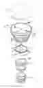
FIG. 1A shows an exploded, view of a lighting device according to one embodiment of the present invention;
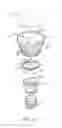
FIG. 1B shows an external view of an assembled lighting device of FIG. 1A;
FIG. 1C shows a cross-sectional view of the assembled lighting device of FIG. 1A;
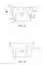
FIG. 2A illustrates a cross-sectional view of the bottom. housing along a section line 2A-2A′ of FIG. 1A; and
FIG. 2B illustrates a cross-sectional view of the bottom. housing along a section line 2B-2B′ of FIG. 1A.
DETAILED DESCRIPTION OF THE INVENTION
FIG. 1A shows an exploded view of a lighting device according to one embodiment of the present invention, FIG. 1B shows an external view of an assembled lighting device, and FIG. 1C shows a cross-sectional view of the assembled lighting device. Although a light-emitting diode (LED) bulb is demonstrated in the embodiment, other lighting elements such as an organic light-emitting diode (OLED) may be used as well.
In the embodiment, the lighting device includes a lamp cover 10, a bottom housing 12, a middle housing 14, a top housing 16, and a lamp head 18. Specifically, the lamp cover 10 may be used for diffusing light, protection and dust proof. In the specification, the orientation, of the lighting device is defined according to its normal use, that is, the lamp head 18 as the top and the lamp cover 10 as the bottom.
FIG. 2A and FIG. 21B show cross-sectional views of the bottom. housing 12, where FIG. 2A illustrates the cross-sectional view along a section line 2A-2A′ of FIG. 1A, and FIG. 21B illustrates the cross-sectional view along a section line 2B-2B′ of FIG. 1A. The lamp cover 10 is coupled to the bottom side of the bottom housing 12. A bottom surface 120 of the bottom housing 12 is capable of supporting a lighting module 11 (e.g., an LED module), which may be fastened to the bottom surface 120 of the bottom housing 12 via at least one threaded hole 121. The sidewall of the bottom housing 12 is equipped with at least one heat dissipation blade 122 for dissipating LED-generated. heat out of the lighting device. At least one line hole 123 passes between the top side and the bottom side of the bottom housing 12. The line hole 123 may accommodate connecting wires between the lighting module 11 and a power module (disposed in a space defined by the middle housing 14 and the top housing 16). An air cell 124 is formed in the bottom housing 12 near its top side. The air cell 124 may communicate with outside of the lighting device via an air passage 125 and an air entrance port 126 (disposed on the sidewall of the bottom housing 12). In the embodiment, the bottom housing 12 may be, for example, made of aluminum, copper or ceramic.
In the embodiment, the middle housing 14 is disposed. between the bottom housing 12 and the top housing 16, and is primarily used to isolate one from the other such that the LED-generated heat in the bottom housing 12 will not directly affect the power module in the top housing 16. Further, a punctured hole 141 is disposed on a bottom surface 140 of the middle housing 14, and an air exit port 142 is disposed on the sidewall of the middle housing 14. Accordingly, an air channel is thus formed along the air entrance port 126 (of the bottom housing 12), the air passage 125 (of the bottom housing 12), the air cell 124 (of the bottom housing 12), the punctured hole 141 (of the middle housing 14) and the air exit port 142 (of the middle housing 14). Therefore, external air enters the lighting device via the air entrance port 126 and exits from the air exit port 142, thereby carrying the LED-generated heat out of the lighting device. The heat dissipation efficiency may be improved by the air channel in accordance with the heat dissipation blade 122. However, the heat dissipation may be reached using only the air channel.
The middle housing 14 is coupled to the top side of the bottom. housing 12. In the embodiment, the middle housing 14 has a hollow fixing pillar 143 extended from the bottom surface 140 of the middle housing 14. The middle housing 14 may be fixed to the bottom housing 12 via the hollow fixing pillar 143 by screwing. The hollow fixing pillar 143 may be replaced with other fixing means such as a hook. Moreover, the middle housing 14 may include hollow line pillar 144 used, in accordance with the line hole 123, to accommodate connecting wires between the lighting module 11 and a power module. It is appreciated that the connecting wires may pass the middle housing 14 without using the hollow line pillar 144.
The top housing 16 is coupled to the top side of the middle housing 14. In the embodiment, the top housing 16 may be fastened. to the middle housing 14 via at least one hook 160. The top housing 16 of the embodiment may be made of plastic or similar material. The lamp head 18 may be made of metal material. The lamp head 18, as an electrode of the lighting device, may cover the sidewall of the top housing 16.
According to one aspect of the embodiment, adhesive dripping 127 may be applied on peripheral area near the top side of the bottom housing 12. The adhesive dripping 127 provides both fastening and water proof between the bottom housing 12 and the middle housing 14.
Although specific embodiments have been illustrated and described, it will be appreciated by those skilled in the art that various modifications may be made without departing from the scope of the present invention, which is intended to be limited solely by the appended claims.
Claims
What is claimed is:1. A lighting device, comprising:
a bottom housing having a bottom surface for supporting a lighting module;
a middle housing coupled to a top side of the bottom housing;
a top housing coupled to a top side of the middle housing, wherein the middle housing is disposed between the bottom housing and the top housing; and
a lamp head covering a sidewall of the top housing.
2. The lighting device of claim 1, wherein the lighting module comprises at least one light-emitting diode (LED) or organic light-emitting diode (OLED).
3. The lighting device of claim 1, wherein the bottom housing has a threaded hole, by which the lighting module is fastened to the bottom housing.
4. The lighting device of claim 1, wherein the bottom housing comprises at least one heat dissipation blade disposed on a sidewall of the bottom housing.
5. The lighting device of claim 1, wherein the bottom housing has a line hole that passes between a top side and a bottom side of the bottom housing.
6. The lighting device of claim 1, wherein an air cell is formed in the bottom housing, the air cell communicating with outside of the lighting device via an air passage and an air entrance port disposed on a sidewall of the bottom housing.
7. The lighting device of claim 1, wherein the bottom housing is made of aluminum, copper or ceramic.
8. The lighting device of claim 6, wherein a punctured hole is disposed on a bottom surface of the middle housing, and an air exit port is disposed on a sidewall of the middle housing, thereby the air exit port and the punctured hole communicating with the air cell of the bottom housing.
9. The lighting device of claim 1, wherein the middle housing comprises a hollow fixing pillar extended from a bottom surface of the middle housing, wherein the middle housing is fixed to the bottom housing via the hollow fixing pillar by screwing.
10. The lighting device of claim 1, wherein the middle housing comprises a hollow line pillar.
11. The lighting device of claim 1, wherein the top housing comprises a hook for fastening the top housing to the middle housing.
12. The lighting device of claim 1, wherein adhesive dripping applied on peripheral area near the top side of the bottom housing for providing water proof between the bottom housing and the middle housing.
13. The lighting device of claim 1, further comprising a lamp cover coupled to a bottom side of the bottom housing.
Images & Drawings included:
Sources:
- United States Patent and Trademark Office - verify current appl. status at the USPTO↗
Similar patent applications:
- » 20250003578
LIGHTING DEVICES, LIGHTING DEVICE ASSEMBLIES, AND METHODS OF ASSEMBLING LIGHTING DEVICES AND LIGHTING DEVICE ASSEMBLIES - » 20130299788
Organic light-emitting device, coating liquid for forming organic light-emitting device, material for forming organic light-emitting device, light source device using organic light-emitting device, and organic light-emitting device producing method - » 20170175972
Light emitting device, LED light bulb, spot lighting device, lighting device, and lighting equipment - » 20170105253
Lighting device, lighting arrangement comprising lighting device and method for operating a lighting device - » 20150373801
Lighting device, lighting arrangement comprising lighting device and method for operating a lighting device - » 20180168010
Lighting device, lighting arrangement comprising lighting device and method for operating a lighting device - » 20130228803
Light-emitting device, lighting device, light-emitting device assembly, and method for producing light-emitting device - » 20150194578
Light-emitting device, lighting device including the light-emitting device, and method of manufacturing the light-emitting device - » 20130069525
Light-emitting device, lighting device including the light-emitting device, and method of manufacturing the light-emitting device - » 20120305971
LIGHT EMITTING DEVICE LENS, LIGHT EMITTING DEVICE MODULE INCLUDING LIGHT EMITTING DEVICE LENS AND METHOD FOR MANUFACTURING LIGHT EMITTING DEVICE MODULE USING LIGHT EMITTING DEVICE LENS
Recent applications in this class:
- » 20250129926 2025-04-24
Lampshade Assembly and Snoot Tube Applying Same - » 20240384866 2024-11-21
Systems and methods for providing lighting using modular heat sink structures and lenses - » 20240377054 2024-11-14
DISPLAY DEVICE - » 20240219018 2024-07-04
Modular Lighting Apparatus with Cooling Channel - » 20240085012 2024-03-14
3D PRINTED INTEGRATED THERMAL MANAGEMENT AND LIGHT TRANSFER STRUCTURES - » 20240060636 2024-02-22
PHOSPHOR WHEEL - » 20240060635 2024-02-22
LED lamp with heat sink and with power supply received in housing - » 20240003530 2024-01-04
Light - » 20230392779 2023-12-07
HEATSINK, ACTIVE ENERGY IRRADIATION DEVICE, AND ACTIVE ENERGY IRRADIATION SYSTEM - » 20230042143 2023-02-09
ILLUMINATION SAFEGUARD ADAPTER FOR OUTSIDE WALL LIGHTING FIXTURES WITH BODY THAT EXTENDS BEYOND LIGHT BULB TO MAINTAIN LIGHT TRANSMISSION WHILE REDUCING VERTICAL LIGHT POLLUTION
Recent applications for this Assignee:
- » 20140286020 2014-09-25
LIGHTING DEVICE - » 20120176046 2012-07-12
Lighting device - » 20120176046 2012-07-12
Lighting device - » 20120127703 2012-05-24
LAMP HEAD MODULE and LED LAMP - » 20120069601 2012-03-22
Lighting master and lighting device - » 20110298380 2011-12-08
REPORT SYSTEM AND METHOD USING LIGHT-EMITTING DIODE LAMP - » 20110241548 2011-10-06
Illumination system adaptable to a cooling appliance