Fixing apparatus for electronic device
US20120170235A1
2012-07-05
13/048,884
2011-03-16
✅ Patent granted
US 8,406,010 B2
2013-03-26
-
-
Lisa Lea Edmonds | Xanthia C Cunningham
Altis Law Group, Inc.
2031-06-21
Abstract:
A fixing apparatus includes a bottom wall, a circuit board, and a supporting member. The circuit board is mounted on the bottom wall, with a space defined between the circuit board and the bottom wall. A connector is installed on the circuit board adjacent to an end of the circuit board, to be electrically connected to the electronic device. The supporting member is supported on the bottom wall. A first end of the supporting member is inserted into the space between the circuit board and the bottom wall, and engages with the circuit board. A second end of the supporting member is exposed out of the end of the circuit board adjacent to the connector, to support the electronic device.
Assignee:
- HON HAI PRECISION INDUSTRY CO., LTD. 12,833 🇹🇼 Tu-Cheng, Taiwan
- HON HAI PRECISION INDUSTRY CO., LTD. 10,014 🇹🇼 New Taipei, Taiwan
Applicant:
Interested in similar patents?
Get notified when new applications in this technology area are published.
Classification:
G06F1/183 » CPC main
Details not covered by groups - and; Constructional details or arrangements; Packaging or power distribution Internal mounting support structures, e.g. for printed circuit boards, internal connecting means
H05K7/00 IPC
Constructional details common to different types of electric apparatus
H05K7/00 IPC
Constructional details common to different types of electric apparatus
H05K7/02 IPC
Constructional details common to different types of electric apparatus Arrangements of circuit components or wiring on supporting structure
H05K7/02 IPC
Constructional details common to different types of electric apparatus Arrangements of circuit components or wiring on supporting structure
H05K7/04 IPC
Constructional details common to different types of electric apparatus; Arrangements of circuit components or wiring on supporting structure on conductive chassis
H05K7/04 IPC
Constructional details common to different types of electric apparatus; Arrangements of circuit components or wiring on supporting structure on conductive chassis
Description
BACKGROUND
1. Technical Field
The present disclosure relates to a fixing apparatus for an electronic device.
2. Description of Related Art
Many electronic devices, such as embedded universal serial bus (eUSB) devices, are installed on circuit boards. However, even though the electronic device may only use a little space at their connection points, space between the electronic device and the circuit board will be wasted because the distance between the electronic device and the circuit board is too small, meaning that all but devices with the low profiles are excluded from being installed on the circuit board below the electronic device.
BRIEF DESCRIPTION OF THE DRAWINGS
Many aspects of the present embodiments can be better understood with reference to the following drawings. The components in the drawings are not necessarily drawn to scale, the emphasis instead being placed upon clearly illustrating the principles of the present embodiments. Moreover, in the drawing, all the views are schematic, and like reference numerals designate corresponding parts throughout the several views.
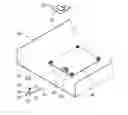
FIG. 1 is an exploded, isometric view of an embodiment of a fixing apparatus together with an electronic device.
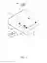
FIG. 2 is an assembled, isometric view of FIG. 1.
DETAILED DESCRIPTION
The disclosure, including the accompanying drawings, is illustrated by way of example and not by way of limitation. It should be noted that references to “an” or “one” embodiment in this disclosure are not necessarily to the same embodiment, and such references mean at least one.
Referring to FIG. 1, an embodiment of a fixing apparatus is provided to fix an electronic device 20 to a body such as a circuit board 40. The fixing apparatus includes a bottom wall 31, the circuit board 40, and a supporting member 10. In this embodiment, the electronic device 20 is an embedded universal serial bus (eUSB) device. A through hole 21 is defined in the electronic device 20, adjacent to an end of the electronic device 20.
The supporting member 10 includes a plate 12. A supporting foot 13 perpendicularly extends down from a first end of the plate 12. A post 14 perpendicularly extends up from the first end of the plate 12. Two spaced resilient hooking arms 142 extend up from a top of the post 14. Two spaced hooks 16 extend up from a second end of the plate 12 opposite to the first end.
The bottom wall 31 is a part of a chassis 30 of a computer. The circuit board 40 is mounted on the bottom wall 31, and a space 312 is defined between the circuit board 40 and the bottom wall 31. Two spaced slots 45 are defined in the circuit board 40, adjacent to an end of the circuit board 40. A connector 42 is installed on the circuit board 40 between the slots 45, to be electrically connected to the electronic device 20. In this embodiment, the connector 42 is a eUSB connector.
Referring to FIG. 2, in assembly, the second end of the supporting member 10 is inserted into the space 312 between the circuit board 40 and the bottom wall 31. The hooks 16 of the supporting member 10 are extended through the slots 45 and engage with a top of the circuit board 40. The first end of the supporting member 10 is exposed out of the end of the circuit board 40 adjacent to the connector 42, with the supporting foot 13 supported by the bottom wall 31. Thereby, the supporting member 10 is fixed on the bottom wall 31. The electronic device 20 is placed on the supporting member 10 and the connector 42, with a connector (not shown) on a bottom side of the electronic device 20 aligning with the connector 42 of the circuit board 40, and the through hole 21 of the electronic device 20 aligning with the hooking arms 142 of the post 14 of the supporting member 10. The electronic device 20 is pressed down and connected to the connector 42 of the circuit board 40 with the connector of the electronic device 20. The hooking arms 142 of the post 14 are deformed to extend through the through hole 21 of the electronic device 20. After extending through the through hole 21, the hooking arms 142 restore and engage with a top of the electronic device 20. The electronic device 20 is supported on the post 14. Thereby, the electronic device 20 is fixed to the circuit board 40. In this embodiment, only a part of the electronic device 20 is fixed over the circuit board 40, which occupies less space of the circuit board 40
It is to be understood, however, that even though numerous characteristics and advantages of the embodiments have been set forth in the foregoing description, together with details of the structure and function of the embodiments, the disclosure is illustrative only, and changes may be made in details, especially in matters of shape, size, and arrangement of parts within the principles of the embodiments to the full extent indicated by the broad general meaning of the terms in which the appended claims are expressed.
Claims
What is claimed is:1. A fixing apparatus for an electronic device, the fixing apparatus comprising:
a bottom wall;
a circuit board mounted on the bottom wall, with a space defined between the circuit board and the bottom wall, a connector installed on the circuit board adjacent to an end of the circuit board, to be electrically connected to the electronic device; and
a supporting member supported on the bottom wall, wherein a first end of the supporting member is inserted into the space between the circuit board and the bottom wall, and engages with the circuit board, a second end of the supporting member is exposed out of the end of the circuit board adjacent to the connector, to support the electronic device.
2. The fixing apparatus of claim 1, wherein two slots are defined in the circuit board adjacent to the connector, the supporting member comprises a plate, two hooks extend up from a first end of the plate, to extend through the corresponding slots and engage with a top of the circuit board.
3. The fixing apparatus of claim 2, wherein a supporting foot extends down from a second end of the plate, to support the plate on the bottom wall.
4. The fixing apparatus of claim 2, wherein a post extends up from a second end of the plate to support the electronic device, and two spaced resilient hooking arms extend up from a top of the post, for extending through a through hole of the electronic device and engage with a top of the electronic device.
Images & Drawings included:

Sources:
- United States Patent and Trademark Office - verify current appl. status at the USPTO↗
Similar patent applications:
- » 20160219731
Fixing device and electronic apparatus with the fixing device - » 20070076395
COMPONENT-FIXING DEVICE, AND PRINTED CIRCUIT BOARD AND ELECTRONIC APPARATUS WITH COMPONENT-FIXING DEVICE - » 20120257360
FIXING APPARATUS FOR ELECTRONIC DEVICE - » 20160345453
FIXING APPARATUS AND ELECTRONIC DEVICE HAVING SAME - » 20130258611
ELECTRONIC APPARATUS AND FIXING DEVICE THEREOF - » 20220007534
Detachably fixing device and electronic apparatus casing therewith - » 20110256439
BATTERY FIXING APPARATUS AND ELECTRONIC DEVICE USING THE SAME - » 20100035136
BATTERY FIXING APPARATUS AND ELECTRONIC DEVICE USING THE SAME - » 20200267868
Electronic device including cable fixing apparatus - » 20170245386
Electronic device including cable fixing apparatus
Recent applications in this class:
- » 20250271911 2025-08-28
FIXING ASSEMBLY AND ELECTRONIC DEVICE - » 20250231597 2025-07-17
APPARATUS FOR ADJUSTABLE DEPTH OF A MODULE WITHIN A CHASSIS - » 20250224780 2025-07-10
METHODS AND APPARATUS TO INCREASE NUMBER OF DIMMs PER SOCKET AND/OR ENHANCE COOLING OF DIMMs - » 20250224779 2025-07-10
ADAPTER FOR CHASSIS AND CABINET ASSEMBLY - » 20250199592 2025-06-19
SERVER AND ELECTRONIC DEVICE - » 20250190034 2025-06-12
FULLY INTEGRATED QUANTUM COMPUTER - » 20250138602 2025-05-01
HEAT SINKS FOR BARE DIE MULTI-CHIP PACKAGES - » 20250138601 2025-05-01
FIXING ASSEMBLY, MOTHERBOARD HAVING THE FIXING ASSEMBLY, AND ELECTRONIC DEVICE HAVING THE MOTHERBOARD - » 20250138600 2025-05-01
LAPTOP COMPUTER - » 20250138599 2025-05-01
M.2 CARD ADAPTER AND HEATSINK
Recent applications for this Assignee:
- » 20250218287 2025-07-03
METHOD OF GENERATING AND PROMPTING TRAFFIC INFORMATION, AND ROADSIDE DEVICE THEREOF - » 20250178535 2025-06-05
METHOD FOR CONSTRUCTING 3D PANORAMIC VIEW MODEL, VEHICLE-MOUNTED DEVICE, AND STORAGE MEDIUM - » 20250074444 2025-03-06
METHOD FOR EARLY WARNING A BLIND AREA, ELECTRONIC DEVICE AND STORAGE MEDIUM - » 20240416754 2024-12-19
DISPLAY CONTROL DEVICE, DISPLAY EQUIPMENT, AND VEHICLE EMPLOYING DEVICE - » 20240411051 2024-12-12
Light-emitting device array and optical transceiver system having the same - » 20240324114 2024-09-26
DISPLAY CONTROL DEVICE AND VEHICLE EMPLOYING DEVICE - » 20240295957 2024-09-05
METHOD FOR CONTROLLING ELECTRONIC DEVICE, ELECTRONIC DEVICE AND COMPUTER STROAGE MEDIUM EMPLOYING METHOD - » 20240257357 2024-08-01
METHOD FOR DETECTING OBSTACLES, ELECTRONIC DEVICE, AND STORAGE MEDIUM - » 20240203133 2024-06-20
LANE LINE RECOGNITION METHOD, ELECTRONIC DEVICE AND STORAGE MEDIUM - » 20240194999 2024-06-13
Robot using limiting device for locking battery