Wheel type exercising device
US20120172184A1
2012-07-05
12/980,435
2010-12-29
✅ Patent granted
US 8,414,461 B2
2013-04-09
-
-
Jerome W Donnelly
Alan Kamrath | Kamrath IP Lawfirm, P.A.
2031-10-04
Abstract:
An exercising device includes a handle, at least one support member secured on the handle, at least one rotation wheel rotatably mounted on the handle, and at least one elastic cord mounted between the at least one support member and the at least one rotation wheel. Preferably, the exercising device comprises two support members, a rotation wheel and a plurality of elastic cords. Thus, the elastic cords are mounted between the rotation wheel and the support members to provide a buffering effect to decelerate the forward movement of the rotation wheel and to provide a pulling force to accelerate the backward movement of the rotation wheel so as to balance the forward and backward movement of the rotation wheel and to prevent the user from being strained or hurt during the reciprocal movement of the rotation wheel.
Assignee:
- Seeds Innovative Design Inc. 1 🇹🇼 Dali, Taiwan
Applicant:
Interested in similar patents?
Get notified when new applications in this technology area are published.
Classification:
A63B21/0552 » CPC main
Exercising apparatus for developing or strengthening the muscles or joints of the body by working against a counterforce, with or without measuring devices using resilient force-resisters extension element type Elastic ropes or bands
A63B21/00181 » CPC further
Exercising apparatus for developing or strengthening the muscles or joints of the body by working against a counterforce, with or without measuring devices comprising additional means assisting the user to overcome part of the resisting force, i.e. assisted-active exercising
A63B21/0435 » CPC further
Exercising apparatus for developing or strengthening the muscles or joints of the body by working against a counterforce, with or without measuring devices using resilient force-resisters attached to static foundation, e.g. a user; Anchored at two end points, e.g. installed within an apparatus One or both ends being anchored to a rotating element
A63B21/169 » CPC further
Exercising apparatus for developing or strengthening the muscles or joints of the body by working against a counterforce, with or without measuring devices; Supports for anchoring force-resisters for anchoring on or against a wall
A63B22/20 » CPC further
Exercising apparatus specially adapted for conditioning the cardio-vascular system, for training agility or co-ordination of movements using rollers, wheels, castors or the like, to be moved over the floor or other surface, during exercising
A63B23/0211 » CPC further
Exercising apparatus specially adapted for particular parts of the body for the abdomen, the spinal column or the torso muscles related to shoulders (e.g. chest muscles); Abdomen moving torso with immobilized lower limbs
A63B23/03541 » CPC further
Exercising apparatus specially adapted for particular parts of the body for limbs, i.e. upper or lower limbs, e.g. simultaneously; For both arms together or both legs together; Aspects related to the co-ordination between right and left side limbs of a user; With separate means driven by each limb, i.e. performing different movements Moving independently from each other
A63B23/1209 » CPC further
Exercising apparatus specially adapted for particular parts of the body for limbs, i.e. upper or lower limbs, e.g. simultaneously for upper limbs or related muscles, e.g. chest, upper back or shoulder muscles Involving a bending of elbow and shoulder joints simultaneously
A63B2208/0204 » CPC further
Characteristics or parameters related to the user or player posture Standing on the feet
A63B2208/0219 » CPC further
Characteristics or parameters related to the user or player posture; Kneeling on hands and knees
A63B2225/74 » CPC further
Miscellaneous features of sport apparatus, devices or equipment with powered illuminating means, e.g. lights
A63B23/02 IPC
Exercising apparatus specially adapted for particular parts of the body for the abdomen, the spinal column or the torso muscles related to shoulders (e.g. chest muscles)
A63B21/00 IPC
Exercising apparatus for developing or strengthening the muscles or joints of the body by working against a counterforce, with or without measuring devices
Description
BACKGROUND OF THE INVENTION
1. Field of the Invention
The present invention relates to an exercising device and, more particularly, to a wheel type exercising device.
2. Description of the Related Art
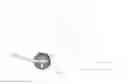
A conventional exercise wheel 70 in accordance with the prior art shown in FIG. 1 comprises a handle 72, and a wheel body 71 rotatably mounted on the handle 72. In operation, the user's two hands can hold the handle 72 to move the wheel body 71 on the ground forward and backward in a reciprocal manner so that the user has to apply a larger force to move the wheel body 71 successively, thereby achieving an exercising effect to train and build the user's abdomen, arms and legs. However, the user's hands have to apply a larger force on the handle 72 to support and balance his body during the forward and backward movement of the wheel body 71 so that the user's muscles are easily strained or hurt during the exercising process.
BRIEF SUMMARY OF THE INVENTION
In accordance with the present invention, there is provided an exercising device, comprising a handle, at least one support member secured on the handle, at least one rotation wheel rotatably mounted on the handle and rotatable relative to the at least one support member, and at least one elastic cord mounted between the at least one support member and the at least one rotation wheel and extendable to provide a buffering effect to rotation of the at least one rotation wheel when the at least one rotation wheel is rotatable relative to the at least one support member.
According to one embodiment of the present invention, the exercising device comprises two support members, a rotation wheel and a plurality of elastic cords.
According to the primary advantage of the present invention, the elastic cords are mounted between the rotation wheel and the support members to provide a buffering and damping effect to decelerate the forward movement of the rotation wheel and to provide a pulling force to accelerate the backward movement of the rotation wheel so as to balance the forward and backward movement of the rotation wheel and to prevent the user from being strained or hurt during the reciprocal movement of the rotation wheel.
According to another advantage of the present invention, the elastic cords provide a buffering effect to decelerate the forward movement of the rotation wheel and provide a pulling force to accelerate the backward movement of the rotation wheel to balance the forward and backward movement of the rotation wheel so that the user can operate the exercising device easily, smoothly and long.
Further benefits and advantages of the present invention will become apparent after a careful reading of the detailed description with appropriate reference to the accompanying drawings.
BRIEF DESCRIPTION OF THE SEVERAL VIEWS OF THE DRAWING(S)
FIG. 1 is a perspective view of a conventional exercising device in accordance with the prior art.
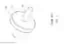
FIG. 2 is a perspective view of an exercising device in accordance with the preferred embodiment of the present invention.
FIG. 3 is an exploded perspective view of the exercising device as shown in FIG. 2.
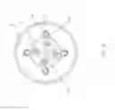
FIG. 4 is a side view of the exercising device as shown in FIG. 2.
FIG. 5 is a schematic operational view of the exercising device as shown in FIG. 4.
FIG. 6 is a schematic operational view of the exercising device as shown in FIG. 2.
FIG. 7 is a side view of the exercising device as shown in FIG. 6.
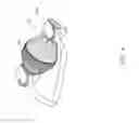
FIG. 8 is a perspective view of an exercising device in accordance with another preferred embodiment of the present invention.
FIG. 9 is an exploded perspective view of the exercising device as shown in FIG. 8.
FIG. 10 is a side operational view of the exercising device as shown in FIG. 8.
FIG. 11 is a perspective view of an exercising device in accordance with another preferred embodiment of the present invention.
FIG. 12 is an exploded perspective view of the exercising device as shown in FIG. 11.
FIG. 13 is a side operational view of the exercising device as shown in FIG. 11.
DETAILED DESCRIPTION OF THE INVENTION
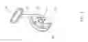
Referring to the drawings and initially to FIGS. 2 and 3, an exercising device in accordance with the preferred embodiment of the present invention comprises a handle 31, at least one support member 20 secured on the handle 31, at least one rotation wheel 10 rotatably mounted on the handle 31 and rotatable relative to the at least one support member 20, and at least one elastic cord 50 mounted between the at least one support member 20 and the at least one rotation wheel 10 and extendable to provide a buffering effect to rotation of the at least one rotation wheel 10 when the at least one rotation wheel 10 is rotatable relative to the at least one support member 20.
In the preferred embodiment of the present invention, the exercising device comprises two support members 20, a rotation wheel 10 and a plurality of elastic cords 50.
The rotation wheel 10 is disposed between the support members 20. The rotation wheel 10 has a central portion provided with a shaft hole 11 rotatably mounted on the handle 31 and has a periphery provided with a plurality of through holes 12 to allow passage of the elastic cords 50. Preferably, the rotation wheel 10 is provided with a light emitter (such as an LED), an oscillation switch and a battery.
Each of the support members 20 has a disk shape. Each of the support members 20 has a central portion provided with a mounting hole 21 secured on the handle 31 and has a periphery provided with a plurality of through bores 22 to allow passage of the elastic cords 50.
The handle 31 is extended through the shaft hole 11 of the rotation wheel 10 and has two opposite ends each inserted into and secured in the mounting hole 21 of a respective one of the support members 20.
The elastic cords 50 are mounted between the rotation wheel 10 and the support members 20. The elastic cords 50 are extended through the through holes 12 of the rotation wheel 10 and the through bores 22 of each of the support members 20. The elastic cords 50 are affixed to the support members 20 respectively by a plurality of locking members 23. Each of the elastic cords 50 has a tubular shape. The locking members 23 are inserted into the elastic cords 50 and are locked onto the through bores 22 of each of the support members 20 so that the elastic cords 50 are locked onto each of the support members 20. Each of the locking members 23 has a size greater than that of each of the through bores 22 of each of the support members 20.
In operation, referring to FIGS. 6 and 7 with reference to FIGS. 2-5, the exercising device further comprises a holding member 40 mounted on the two opposite ends of the handle 31 to facilitate a user holding the exercising device. Preferably, the holding member 40 is a substantially U-shaped bracket. In such a manner, the user's two hands can hold the holding member 40 to move the rotation wheel 10 forward and backward in a reciprocal manner so that the user has to apply a larger force to move the rotation wheel 10 successively, thereby achieving an exercising effect to train and build the user's abdomen, arms and legs. At this time, when the rotation wheel 10 is moved forward, the rotation wheel 10 is rotated relative to the support members 20 forward to stretch the elastic cords 50 so that the elastic cords 50 are extended to provide a buffering effect to rotation of the rotation wheel 10. In addition, when the rotation wheel 10 is moved backward, the rotation wheel 10 is rotated relative to the support members 20 backward by the restoring force of the elastic cords 50 so that the rotation wheel 10 is moved backward easily and smoothly by aid of the elastic cords 50. Thus, the elastic cords 50 provide a buffering effect to decelerate the forward movement of the rotation wheel 10 and provide a pulling force to accelerate the backward movement of the rotation wheel 10 so as to balance the forward and backward movement of the rotation wheel 10 and to prevent the user from being hurt during the reciprocal movement of the rotation wheel 10.
Accordingly, the elastic cords 50 are mounted between the rotation wheel 10 and the support members 20 to provide a buffering and damping effect to decelerate the forward movement of the rotation wheel 10 and to provide a pulling force to accelerate the backward movement of the rotation wheel 10 so as to balance the forward and backward movement of the rotation wheel 10 and to prevent the user from being strained or hurt during the reciprocal movement of the rotation wheel 10. In addition, the elastic cords 50 provide a buffering effect to decelerate the forward movement of the rotation wheel 10 and provide a pulling force to accelerate the backward movement of the rotation wheel 10 to balance the forward and backward movement of the rotation wheel 10 so that the user can operate the exercising device easily, smoothly and long.
Referring to FIGS. 8-10, each of the support members 20 is an upright plate, and the support members 20 are combined together so as to form a substantially U-shaped frame to support the handle 31 and the rotation wheel 10. The exercising device further comprises a pull cord 60 mounted around the rotation wheel 10, and a holding member 40 connected with the pull cord 60. Thus, when the user applies a pulling force on the holding member 40, the pull cord 60 is pulled by the holding member 40 to drive and rotate the rotation wheel 10 relative to the support members 20
Referring to FIGS. 11-13, the exercising device comprises a support member 20, two rotation wheels 10 and a plurality of elastic cords 50. The rotation wheels 10 are located at two opposite sides of the support member 20. Each of the rotation wheels 10 has a central portion provided with a shaft hole 11 rotatably mounted on the handle 31 and has a periphery provided with a plurality of through holes 12 to allow passage of the elastic cords 50. Preferably, each of the rotation wheels 10 is provided with a light emitter (such as an LED), an oscillation switch and a battery. The support member 20 is a substantially inverted T-shaped rack to support the handle 31 and the rotation wheels 10. The support member 20 is disposed between the rotation wheels 10. The support member 20 has a central portion provided with a mounting hole 21 secured on the handle 31 and has a periphery provided with a plurality of through bores 22 to allow passage of the elastic cords 50. The handle 31 is extended through and secured in the mounting hole 21 of the support member 20 and has two opposite ends each extended through the shaft hole 11 of a respective one of the rotation wheels 10. The elastic cords 50 are extended through the through holes 12 of each of the rotation wheels 10 and the through bores 22 of the support member 20. The elastic cords 50 are affixed to the rotation wheels 10 respectively by a plurality of locking members 23. Each of the elastic cords 50 has a tubular shape. The locking members 23 are inserted into the elastic cords 50 and are locked onto the through holes 12 of each of the rotation wheels 10 so that the elastic cords 50 are locked onto each of the rotation wheels 10. Each of the locking members 23 has a size greater than that of each of the through holes 12 of each of the rotation wheels 10. The exercising device further comprises two pull cords 60 mounted around the rotation wheels 10 respectively, and two holding members 40 connected with the pull cords 60 respectively.
Although the invention has been explained in relation to its preferred embodiment(s) as mentioned above, it is to be understood that many other possible modifications and variations can be made without departing from the scope of the present invention. It is, therefore, contemplated that the appended claim or claims will cover such modifications and variations that fall within the true scope of the invention.
Claims
1. An exercising device, comprising:
a handle;
at least one support member secured on the handle;
at least one rotation wheel rotatably mounted on the handle and rotatable relative to the at least one support member; and
at least one elastic cord mounted between the at least one support member and the at least one rotation wheel and extendable to provide a buffering effect to rotation of the at least one rotation wheel when the at least one rotation wheel is rotatable relative to the at least one support member.
2. The exercising device of claim 1, wherein
the exercising device comprises two support members, a rotation wheel and a plurality of elastic cords;
the rotation wheel has a central portion provided with a shaft hole rotatably mounted on the handle and has a periphery provided with a plurality of through holes to allow passage of the elastic cords;
each of the support members has a central portion provided with a mounting hole secured on the handle and has a periphery provided with a plurality of through bores to allow passage of the elastic cords.
3. The exercising device of claim 2, wherein the elastic cords are affixed to the support members respectively by a plurality of locking members.
4. The exercising device of claim 3, wherein
each of the elastic cords has a tubular shape;
the locking members are inserted into the elastic cords and are locked onto the through bores of each of the support members so that the elastic cords are locked onto each of the support members.
5. The exercising device of claim 4, wherein each of the locking members has a size greater than that of each of the through bores of each of the support members.
6. The exercising device of claim 2, wherein
the rotation wheel is disposed between the support members;
the elastic cords are mounted between the rotation wheel and the support members.
7. The exercising device of claim 2, wherein
the handle is extended through the shaft hole of the rotation wheel and has two opposite ends each inserted into and secured in the mounting hole of a respective one of the support members;
the elastic cords are extended through the through holes of the rotation wheel and the through bores of each of the support members.
8. The exercising device of claim 2, wherein the exercising device further comprises a holding member mounted on two opposite ends of the handle.
9. The exercising device of claim 8, wherein the holding member is a substantially U-shaped bracket.
10. The exercising device of claim 2, wherein
each of the support members is an upright plate;
the support members are combined together so as to form a substantially U-shaped frame to support the handle and the rotation wheel.
11. The exercising device of claim 10, wherein the exercising device further comprises:
a pull cord mounted around the rotation wheel;
a holding member connected with the pull cord.
12. The exercising device of claim 2, wherein each of the support members has a disk shape.
13. The exercising device of claim 1, wherein
the exercising device comprises a support member, two rotation wheels and a plurality of elastic cords;
each of the rotation wheels has a central portion provided with a shaft hole rotatably mounted on the handle and has a periphery provided with a plurality of through holes to allow passage of the elastic cords;
the support member has a central portion provided with a mounting hole secured on the handle and has a periphery provided with a plurality of through bores to allow passage of the elastic cords.
14. The exercising device of claim 13, wherein the elastic cords are affixed to the rotation wheels respectively by a plurality of locking members.
15. The exercising device of claim 14, wherein
each of the elastic cords has a tubular shape;
the locking members are inserted into the elastic cords and are locked onto the through holes of each of the rotation wheels so that the elastic cords are locked onto each of the rotation wheels.
16. The exercising device of claim 15, wherein each of the locking members has a size greater than that of each of the through holes of each of the rotation wheels.
17. The exercising device of claim 13, wherein the exercising device further comprises:
two pull cords mounted around the rotation wheels respectively;
two holding members connected with the pull cords respectively.
18. The exercising device of claim 13, wherein
the rotation wheels are located at two opposite sides of the support member;
the support member is a substantially inverted T-shaped rack to support the handle and the rotation wheels;
the support member is disposed between the rotation wheels.
19. The exercising device of claim 13, wherein
the handle is extended through and secured in the mounting hole of the support member and has two opposite ends each extended through the shaft hole of a respective one of the rotation wheels;
the elastic cords are extended through the through holes of each of the rotation wheels and the through bores of the support member.
20. The exercising device of claim 1, wherein the at least one rotation wheel is provided with a light emitter, an oscillation switch and a battery.
Images & Drawings included:


Sources:
- United States Patent and Trademark Office - verify current appl. status at the USPTO↗
Similar patent applications:
- » 20100213017
WHEEL-TYPE RESISTANCE DEVICE FOR AN EXERCISER
Recent applications in this class:
- » 20250288848 2025-09-18
Multi-Purpose Exercise Device - » 20250235732 2025-07-24
STRENGTH TRAINING STATION - » 20250065176 2025-02-27
SYSTEM, METHOD, AND DEVICE FOR DEVELOPING MUSCLE MEMORY AND A BALANCED SWING - » 20240226638 2024-07-11
FITNESS EXERCISE APPARATUS - » 20240216742 2024-07-04
MODULAR RESISTANCE TRAINING SYSTEMS - » 20240131382 2024-04-25
Fitness exercise apparatus - » 20240123276 2024-04-18
Multi-functional exercise device - » 20230218942 2023-07-13
Strength-training apparatus for outdoor use with a hitch or ground receiver - » 20230201648 2023-06-29
BODY STRETCH POSE ASSISTING STRAP AND RELATED METHOD - » 20230104783 2023-04-06
IMPROVED DEVICE FOR SUSPENSION TRAINING