Division mask and method of assembling mask frame assembly by using the same
US20120174863A1
2012-07-12
13/237,383
2011-09-20
✅ Patent granted
US 8,915,213 B2
2014-12-23
-
-
Dah-Wei D Yuan | Binu Thomas
Robert E. Bushnell, Esq.
2031-11-02
Abstract:
In a division mask and a method of assembling a mask frame assembly by using the same, the division mask includes a stick body on which deposition patterns are formed, and a clamping portion which extends from the stick body outward along a longitudinal direction of the stick body, the clamping portion increasing in width from the stick body. By using this structure, since tight tension is exerted on the division mask during the assembly of a mask frame assembly due to an extension portion of the clamping portion, creases are prevented from being formed on the division mask, thus obtaining a precise mask frame assembly.
Assignee:
- SAMSUNG MOBILE DISPLAY CO., LTD. 1,151 🇰🇷 Yongin-city, South Korea
- Samsung Display Co., Ltd. 517 🇰🇷 Giheung-Gu, Yongin, Gyeonggi-Do, South Korea
Applicant:
Interested in similar patents?
Get notified when new applications in this technology area are published.
Classification:
H01L51/00 IPC
Solid state devices using organic materials as the active part, or using a combination of organic materials with other materials as the active part; Processes or apparatus specially adapted for the manufacture or treatment of such devices, or of parts thereof
B05B12/20 » CPC further
Arrangements for controlling delivery; Arrangements for controlling the spray area for controlling the spray area Masking elements, i.e. elements defining uncoated areas on an object to be coated
Y10T29/49826 » CPC further
Metal working; Method of mechanical manufacture Assembling or joining
B23P11/00 IPC
Connecting or disconnecting metal parts or objects by metal-working techniques not otherwise provided for
H01L51/50 » CPC further
Solid state devices using organic materials as the active part, or using a combination of organic materials with other materials as the active part; Processes or apparatus specially adapted for the manufacture or treatment of such devices, or of parts thereof specially adapted for light emission, e.g. organic light emitting diodes [OLED] or polymer light emitting devices [PLED]
C23C14/042 » CPC further
Coating by vacuum evaporation, by sputtering or by ion implantation of the coating forming material; Coating on selected surface areas, e.g. using masks using masks
H01L51/0011 » CPC further
Solid state devices using organic materials as the active part, or using a combination of organic materials with other materials as the active part; Processes or apparatus specially adapted for the manufacture or treatment of such devices, or of parts thereof; Processes specially adapted for the manufacture or treatment of devices or of parts thereof; Deposition of organic semiconductor materials on a substrate using physical deposition, e.g. sublimation, sputtering selective deposition, e.g. using a mask
C23C16/042 » CPC further
Chemical coating by decomposition of gaseous compounds, without leaving reaction products of surface material in the coating, i.e. chemical vapour deposition [CVD] processes; Coating on selected surface areas, e.g. using masks using masks
B05C21/005 » CPC further
Masking devices
B05C11/00 IPC
Component parts, details or accessories not specifically provided for in groups -
C23C14/12 » CPC main
Coating by vacuum evaporation, by sputtering or by ion implantation of the coating forming material characterised by the coating material Organic material
H01L51/56 IPC
Solid state devices using organic materials as the active part, or using a combination of organic materials with other materials as the active part; Processes or apparatus specially adapted for the manufacture or treatment of such devices, or of parts thereof specially adapted for light emission, e.g. organic light emitting diodes [OLED] or polymer light emitting devices [PLED] Processes or apparatus specially adapted for the manufacture or treatment of such devices or of parts thereof
C23C16/04 IPC
Chemical coating by decomposition of gaseous compounds, without leaving reaction products of surface material in the coating, i.e. chemical vapour deposition [CVD] processes Coating on selected surface areas, e.g. using masks
C23C14/04 IPC
Coating by vacuum evaporation, by sputtering or by ion implantation of the coating forming material Coating on selected surface areas, e.g. using masks
Description
CLAIM OF PRIORITY
This application makes reference to, incorporates the same herein, and claims all benefits accruing under 35 U.S.C. §119 from an application earlier filed in the Korean Intellectual Property Office on the 10 of Jan. 2011 and there duly assigned Serial No. 10-2011-0002305.
BACKGROUND OF THE INVENTION
1. Field of the Invention
The present invention relates to division masks used in depositing thin films and methods of assembling mask frame assemblies by using the division masks.
2. Description of the Related Art
In general, among display devices, organic light-emitting display devices have wide viewing angles, excellent contrast, and quick response speeds.
In an organic-light emitting display device, light is emitted by the recombination of holes and electrons which are injected into an anode and a cathode. The organic-light emitting display device has a stack structure in which the emissive layer is inserted between the anode and the cathode. However, since it is difficult for an organic-light emitting display device having this structure to have high luminescent efficiency, an electron injection layer, an electron transfer layer, a hole transfer layer, a hole injection layer and the like are selectively inserted between the emissive layer and each of the anode and the cathode.
Electrodes and intermediate layers, including an emissive layer of an organic-light emitting display device, are formed by using various methods. One of the methods is a deposition method. In order to manufacture an organic-light emitting display device by using the deposition method, a fine metal mask (FMM) having the same patterns as those of a thin film to be formed on a substrate is aligned on the substrate, and then the thin film having desired patterns is formed by depositing a raw material of the thin film.
As the FMM is large in size, more etching errors occur, and a central portion of the FMM is likely to sag due to its weight. Thus, recently, a division mask, formed by forming various mask sticks and attaching the mask sticks onto a frame, has been widely used.
However, the division mask is large in size, having a length of about 1,840 mm in order to satisfy the users' requirements of a large-size display device. Thus, creases may be formed lengthwise in each division mask. That is, as each division mask is long in size, creases may be formed on the division mask, and the division mask is not consistently flat. In this case, various problems may occur also in a deposition process in which fine patterns are to be formed by using the division mask.
Thus, there is a need to prevent creases from being formed on the division mask.
SUMMARY OF THE INVENTION
The present invention provides division masks used in depositing thin films, wherein the formation of creases in the division masks is prevented, and methods of assembling mask frame assemblies by using the division masks.
According to an aspect of the present invention, a division mask comprises: a stick body on which deposition patterns are formed; and a clamping portion which extends from the stick body outward along a longitudinal direction of the stick body, increasing in width from the stick body.
A connection portion between the stick body and the clamping portion may be welded on a frame of a mask frame assembly.
The clamping portion may be removed after the connection portion is welded on the frame.
The clamping portion may include an extension portion having a width which increases from the stick body outward, and which may have a ‘Y’ shape.
According to another aspect of the present invention, a method of assembling a mask frame assembly comprises: preparing a plurality of division masks, each including a stick body on which deposition patterns are formed and a clamping portion which extends from the stick body outward along a longitudinal direction of the stick body, increasing in width from the stick body, and a frame to which the plurality of division masks are attached; and welding the stick body on the frame while tension is exerted on the division mask by holding the clamping portion of the division mask.
The method may further include cutting the clamping portion of the division mask on which the welding is completed.
A connection portion between the stick body and the clamping portion may be welded on the frame when the stick body is welded on the frame.
The clamping portion may include an extension portion having a width which increases from the stick body outward, and which may have a ‘Y’ shape.
By using the above structure, since tight tension is exerted on the division mask during the assembly of a mask frame assembly due to an extension portion of the clamping portion, creases may be prevented from being formed, thus obtaining a precise and stable mask frame assembly.
BRIEF DESCRIPTION OF THE DRAWINGS
A more complete appreciation of the invention, and many of the attendant advantages thereof, will be readily apparent as the same becomes better understood by reference to the following detailed description when considered in conjunction with the accompanying drawings, in which like reference symbols indicate the same or similar components, wherein:
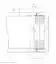
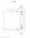
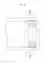
FIG. 1 is a plan view of a division mask according to an embodiment of the present invention;
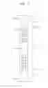
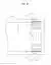
FIG. 2 is a plan view of a mask frame assembly in which the division mask of FIG. 1 and a frame are attached to each other according to an embodiment of the present invention; and
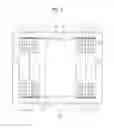
FIGS. 3A thru 3D are plan views used to describe a method of assembling the mask frame assembly of FIG. 2 according to an embodiment of the present invention.
DETAILED DESCRIPTION OF THE INVENTION
The present invention will now be described more fully with reference to the accompanying drawings, in which exemplary embodiments of the invention are shown.
FIG. 1 is a plan view of a division mask according to an embodiment of the present invention, and FIG. 2 is a plan view of a mask frame assembly in which the division mask of FIG. 1 and a frame are attached to each other according to an embodiment of the present invention.
A plurality of division masks 100 are welded on a frame 200 (see FIG. 2) to constitute a mask frame assembly 300. The division mask 100 may be formed of, for example, nickel, nickel alloy, nickel-cobalt alloy or the like.
As shown in FIG. 1, the division mask 100 includes a stick body 110 on which deposition patterns 101 are formed, and clamping portions 120 which are integrally formed with two opposite ends of the stick body 110.
The stick body 110 is welded on the frame 200 (see FIG. 2) so as to constitute the mask frame assembly 300 which is used in a deposition process. The clamping portions 120 are used to exert tension when the stick body 110 is welded onto the frame 200, and are removed during the assembly process. Reference numeral 115 indicates a boundary between the stick body 110 and the clamping portions 120, and is a connection portion which is to be welded onto the frame 200.
The division masks 100 are attached to the frame 200 so as to constitute the mask frame assembly 300 as shown in FIG. 2. The division mask 100 is fixed on the frame 200 by welding the connection portion 115 to the frame 200 so that the deposition patterns 101 are positioned in an opening 201 of the frame 200. The clamping portions 120 are removed after the connection portion 115 is welded onto the frame 200, as indicated by dotted lines in FIG. 2.
Each clamping portion 120 has a ‘Y’ shape and includes an extension portion 121 having a width which increases from the stick body 110 outward along a longitudinal direction of the stick body 110. Thus, the clamping portion 120, including the extension portion 121, has an advantageous structure for exerting tension when the division mask 100 is welded onto the frame 200.
That is, in order to weld the division mask 100 onto the frame 200, connection portions 115 are welded onto the frame 200 while the clamping portions 120, integrated with the two ends of the division mask 100, are being held and pulled by a tensioner (not shown). In this case, when the clamping portions 120, each including the extension portion 121, are held and pulled, since a contact area between the clamping portion 120 and the tensioner is greater than in a case without the extension portion 121, greater tension may be exerted on the division mask 100 as compared to the case without the extension portion 121. Thus, since welding is performed when very tight tension is exerted on the division mask 100, a surface flatness of the division mask 100 is increased so as to thereby remarkably reduce the sizes of creases.
FIGS. 3A thru 3D are plan views used to describe a method of assembling the mask frame assembly of FIG. 2 according to an embodiment of the present invention.
A method of assembling the mask frame assembly 300 by using the division mask 100 may be performed according to the sequence shown in FIGS. 3A thru 3D.
First, the division masks 100 and the frame 200 are prepared. The frame 200 is an outer frame of the mask frame assembly 300 and has a square structure in which the opening 201 is formed in a central portion of the square structure. The connection portions 115 of the division mask 100 are welded and fixed on two sides of the frame 200, respectively.
The division mask 100 is a member which is shaped like a long stick. The deposition patterns 101, positioned in the opening 201, are formed on each of the division masks 100. In addition, as described above, the connection portions 115 between the stick body 110 and the clamping portions 120 are welded on the frame 200.
FIG. 3A illustrates an operation in which a first division mask 100 is attached to the frame 200. Referring to FIG. 3A, the clamping portions 120, integrated with the two ends of the first division mask 100, are held and tightly pulled outward by a tensioner (not shown). Then, tight tension T is exerted on the division mask 100. As described above, since a contact area between the clamping portion 120 and the tensioner is increased due to the extension portion 121, more tension T is exerted on the division mask 100. Thus, the sizes of creases formed on the stick body 110 of the division mask 100 are remarkably reduced, thereby improving the surface flatness of the stick body 110. In this case, the first division mask 100 is fixed on the frame 200 by welding the connection portion 115 onto the frame 200.
After the connection portions 115 are welded onto the frame 200, the clamping portions 120 formed outside the connection portions 115 are cut and removed, as shown in FIG. 3B. As described above, since the clamping portion 120 includes the extension portion 121 having a width which increases from the stick body 110 outward along a longitudinal direction of the stick body 110, the clamping portion 120 may interfere with another clamping portion 120 of another adjacent division mask 100 if the clamping portion 120 is maintained. Thus, prior to welding a second division mask 100, the clamping portions 120 of the first division mask 100 are cut and removed.
Likewise, after welding of the first division mask 100 is completed, the second division mask 100 is welded in the same manner as the first division mask 100, as shown in FIG. 3C. That is, tension T is exerted on the second division mask 100 by holding and pulling the Y-shaped clamping portion 120 of the second division mask 100. In this state, the connection portion 115 is welded onto the frame 200. Also, since a contact area between the clamping portion 120 and the tensioner is increased due to the extension portion 121, more tension T is exerted on the second division mask 100. Thus, the welding may be performed when the sizes of creases formed on the stick body 110 of the second division mask 100 are remarkably reduced.
Also, as shown in FIG. 3D, after the connection portions 115 are welded onto the frame 200, the clamping portions 120 formed outside the connection portions 115 are cut and removed.
Likewise, the other division masks 100 are sequentially welded on the frame 200 so as to completely assemble the mask frame assembly 300, as shown in FIG. 2.
Accordingly, by using the division masks 100, since the division masks 100 are welded on the frame 200 during the assembly of the mask frame assembly 300 while very tight tension is being exerted on the division masks 100, creases may be prevented from being formed on the division masks 100, and thus, a precise mask frame assembly 300 may be obtained.
The sizes of creases formed on the division masks 100 were measured. As a result, a crease had a height of about 19.5 μm in the conventional case without the clamping portion 120 having a ‘Y’ shape. However, in the case of the clamping portion 120 having a ‘Y’ shape, a crease had a height of about 17.8 μm. Thus, about 8.7% of an improvement was obtained. Therefore, a precise and stable mask frame assembly 300 may be obtained.
In addition, the mask frame assembly 300 may be used in various deposition processes, including patterning processes of an organic light-emitting layer.
While the present invention has been particularly shown and described with reference to exemplary embodiments thereof, it will be understood by those of ordinary skill in the art that various changes in form and detail may be made therein without departing from the spirit and scope of the present invention as defined by the following claims.
Claims
What is claimed is:1. A division mask, comprising:
a stick body on which deposition patterns are formed; and
a clamping portion which extends from the stick body outward along a longitudinal direction of the stick body, the clamping portion increasing in width from the stick body.
2. The division mask of claim 1, wherein a connection portion between the stick body and the clamping portion is welded onto a frame of a mask frame assembly.
3. The division mask of claim 2, wherein the clamping portion is removed after the connection portion is welded onto the frame.
4. The division mask of claim 1, wherein the clamping portion comprises an extension portion having a width which increases from the stick body outward.
5. The division mask of claim 4, wherein the clamping portion has a ‘Y’ shape.
6. A method of assembling of a mask frame assembly, comprising the steps of:
preparing a plurality of division masks, each comprising a stick body on which deposition patterns are formed and a clamping portion which extends from the stick body outward along a longitudinal direction of the stick body, the clamping portion increasing in width from the stick body, and a frame to which the plurality of division masks are attached; and
welding the stick body onto the frame while tension is exerted on the division mask by holding the clamping portion of the division mask.
7. The method of claim 6, further comprising cutting the clamping portion of the division mask on which the welding is completed.
8. The method of claim 6, wherein a connection portion between the stick body and the clamping portion is welded onto the frame when the stick body is welded onto the frame.
9. The method of claim 6, wherein the clamping portion comprises an extension portion having a width which increases from the stick body outward.
10. The method of claim 9, wherein the clamping portion has a ‘Y’ shape.
Images & Drawings included:

Sources:
- United States Patent and Trademark Office - verify current appl. status at the USPTO↗
Recent applications in this class:
- » 20250270686 2025-08-28
METHOD FOR PREPARING ORGANIC LIGHT EMITTING DEVICE, PREPARATION SYSTEM, STORAGE MEDIUM AND COMPUTER EQUIPMENT - » 20250236945 2025-07-24
Method of Implanting Atoms in a Substrate and Method of Forming a Quantum Register - » 20240368749 2024-11-07
WINDOW, DISPLAY DEVICE INCLUDING THE SAME, AND METHOD OF MANUFACTURING THE WINDOW - » 20240175117 2024-05-30
FILM FORMING METHOD AND FILM FORMING APPARATUS - » 20230323523 2023-10-12
METHODS AND SYSTEMS FOR FORMING A BLADE OF A SHAVING DEVICE - » 20230183852 2023-06-15
SYSTEMS AND METHODS OF MODULATING FLOW DURING VAPOR JET DEPOSITION OF ORGANIC MATERIALS - » 20210254207 2021-08-19
Microfluidic device and method using double anodic bonding - » 20210054495 2021-02-25
Methods of modulating flow during vapor jet deposition of organic materials - » 20200173013 2020-06-04
Copper passivation - » 20200140990 2020-05-07
Nozzle geometry for organic vapor jet printing
Recent applications for this Assignee:
- » 20160097981 2016-04-07
Optical apparatus and manufacturing method using the same - » 20150041766 2015-02-12
Organic light emitting diode display - » 20150041765 2015-02-12
Display device and method of manufacturing the same - » 20150034919 2015-02-05
Organic light-emitting device - » 20140326973 2014-11-06
Organic light-emitting display device and method of manufacturing the organic light-emitting display device - » 20140320853 2014-10-30
Method and apparatus for measuring damage to an organic layer of a thin film encapsulation - » 20140319474 2014-10-30
Display apparatus - » 20140306197 2014-10-16
Compound and organic light-emitting device comprising the same - » 20140299850 2014-10-09
Organic light-emitting display apparatus providing mirror function - » 20140295601 2014-10-02
Method of forming organic light emitting pattern and apparatus for forming organic light emitting pattern of organic electro-luminescence display using sublimation type thermal transfer method