Optical lens module
US20120176690A1
2012-07-12
13/004,518
2011-01-11
✅ Patent granted
US 8,390,942 B2
2013-03-05
-
-
David N Spector
Muncy, Geissler, Olds & Lowe, PLLC
2031-04-25
Abstract:
An optical lens module is provided, including a first lens, a second lens, a third lens, and an aperture stop formed in the first lens by wafer level processing. The first lens, the second lens, and the third lens are sequentially arranged from an object side to an image side along an optical axis of the optical lens module. The first lens has a convex surface and a concave surface, respectively, on an object side and an image side. The second lens has a concave surface and a convex surface, respectively, on the object side and the image side. The third lens has a convex peripheral portion on the image side, wherein the convex peripheral portion forms a surface with a concave center on the image side, and the surface has a deflection point.
Assignee:
- OMNIVISION TECHNOLOGIES, INC. 1,313 🇺🇸 Santa Clara, CA, United States
- VisEra Technologies Company Limited 67 🇹🇼 Hsinchu, Taiwan
Applicant:
Interested in similar patents?
Get notified when new applications in this technology area are published.
Classification:
G02B13/0035 » CPC main
Optical objectives specially designed for the purposes specified below; Miniaturised objectives for electronic devices, e.g. portable telephones, webcams, PDAs, small digital cameras characterised by the lens design having at least one aspherical surface having three lenses
G02B13/006 » CPC further
Optical objectives specially designed for the purposes specified below; Miniaturised objectives for electronic devices, e.g. portable telephones, webcams, PDAs, small digital cameras employing a special optical element at least one element being a compound optical element, e.g. cemented elements
G02B3/02 IPC
Simple or compound lenses with non-spherical faces
G02B9/12 » CPC further
Optical objectives characterised both by the number of the components and their arrangements according to their sign, i.e. + or - having three components only
Description
BACKGROUND OF THE INVENTION
1. Field of the Invention
This application relates in general to an optical lens module and in particular to an optical lens module with an aperture stop embedded in a lens thereof.
2. Description of the Related Art
Conventional portable cell telephones may comprise a built-in digital camera with an optical lens module. When designing the optical lens module, the ratio of the optical length to the composite focal distance of the optical lens module must be minimized. Design of the optical lens module has become very difficult, as cell telephones are being designed more thin and compact. Moreover, as conventional aperture stop and lenses are usually individual parts assembled to each other, robust connection and accurate positioning therebetween have become a significant challenge.
BRIEF SUMMARY OF INVENTION
An object of the application is to provide an optical lens module with an aperture stop embedded therein. The optical lens module includes a first lens, a second lens, a third lens, and an aperture stop formed in the first lens by wafer level processing. The first lens, the second lens, and the third lens are sequentially arranged from an object side to an image side along an optical axis of the optical lens module. The first lens has a convex surface and a concave surface, respectively, on the object side and the image side. The second lens has a concave surface and a convex surface, respectively, on the object side and the image side. The third lens has a convex peripheral portion on the image side, wherein the convex peripheral portion forms a surface with a concave center on the image side, and the surface has a deflection point.
BRIEF DESCRIPTION OF DRAWINGS
The invention can be more fully understood by reading the subsequent detailed description and examples with references made to the accompanying drawings, wherein:
FIG. 1 is a perspective diagram of an optical lens module according to the first embodiment of the invention;
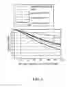
FIG. 2 is a Modulation Transfer Function (MTF) diagram showing several spatial frequency response curves according to the first embodiment of the invention;
FIG. 3 is a perspective diagram of an optical lens module according to the second embodiment of the invention; and
FIG. 4 is a Modulation Transfer Function (MTF) diagram showing several spatial frequency response curves according to the second embodiment of the invention.
DETAILED DESCRIPTION OF INVENTION
First Embodiment
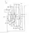
Referring to FIG. 1, the first embodiment of an optical lens module 10 primarily comprises a first lens L1, a second lens L2, a third lens L3, and a plane parallel plate L4. Light can enter the first lens L1 from an object side and sequentially pass through the second lens L2, the third lens L3, and the plane parallel plate L4 to an image side. As shown in FIG. 1, an image sensing plane P of an imaging sensor, such as a CCD (Charge Coupled Device), is disposed on the image side of the lens module 10 to receive light.
In this embodiment, the first lens L1 may be a compound lens comprising three sub-lenses L11-L13. Similarly, the second lens L2 may be a compound lens comprising three sub-lenses L21-L23, and the third lens L3 may be a compound lens comprising three sub-lenses L31-L33. The sub-lenses L12, L22, and L32 may be plane parallel glass plates, and the other sub-lenses L11, L13, L21, L23, L31, and L33 may comprise curable resin material, such as transparent curable silicone resin or UV-curable material.
Specifically, an aperture stop (diaphragm) is formed in the first lens L1 by wafer level processing to define the position of the entrance pupil. In this embodiment, the aperture stop is formed on the surface S2 between the sub-lenses L11 and L12. Since the aperture stop is securely fixed and embedded in the first lens L1 by wafer level processing, accurate positioning and robust connection between the aperture stop and the first lens L1 are achieved.
Table 1-1 and 1-2 illustrate the design parameters of the optical lens module 10 in FIG. 1, wherein the optical lens module 10 has a focal ratio F=2.8.
| TABLE 1-1 | ||||
| Radius | Abbe | |||
| Surface | of Curvature | Distance (mm) | Refractivity | Number |
| S1 | 1.04 | |||
| d1 = 0.28 | 1.475 | 59.5 | ||
| S2 (aperture stop) | ∞ | |||
| d2 = 0.40 | 1.516 | 62.6 | ||
| S3 | ∞ | |||
| d3 = 0.02 | 1.475 | 59.5 | ||
| S4 | 14.84 | |||
| d4 = 0.34 | ||||
| S5 | −1.56 | |||
| d5 = 0.02 | 1.591 | 31 | ||
| S6 | ∞ | |||
| d6 = 0.30 | 1.516 | 62.6 | ||
| S7 | ∞ | |||
| d7 = 0.30 | 1.591 | 31 | ||
| S8 | −0.87 | |||
| d8 = 0.02 | ||||
| S9 | −2.94 | |||
| d9 = 0.14 | 1.591 | 31 | ||
| S10 | ∞ | |||
| d10 = 0.50 | 1.516 | 62.6 | ||
| S11 | ∞ | |||
| d11 = 0.20 | 1.596 | 49.5 | ||
| S12 | 1.47 | |||
| d12 = 0.10 | ||||
| S13 | ∞ | |||
| d13 = 0.40 | 1.516 | 62.6 | ||
| S14 | ∞ | |||
| d14 = 0.47 | ||||
| TABLE 1-2 | |
| Aspheric Coefficiencies |
| Surface | K | A4 | A6 | A8 | A10 | A12 | A14 | A16 |
| S1 | −0.015903981 | 0.010661737 | 0.101027391 | −1.041507211 | 4.987836924 | −7.322415588 | ||
| S2 (aperture stop) | ||||||||
| S3 | ||||||||
| S4 | 0.107518332 | 0.09460356 | 0.639419603 | 0.011888898 | −2.414736278 | |||
| S5 | −2.115726541 | −0.088633717 | 0.894786326 | −3.611759143 | 10.23364604 | −11.60821937 | ||
| S6 | ||||||||
| S7 | ||||||||
| S8 | −0.62551149 | 0.174298024 | 0.032905937 | 0.237108666 | 0.273944609 | −0.36201161 | ||
| S9 | −0.326900121 | 0.14702227 | −0.153167051 | 0.170726554 | −0.416487816 | |||
| S10 | ||||||||
| S11 | ||||||||
| S12 | −8.536388923 | −0.190089713 | 0.088904108 | −0.045077698 | 0.004423103 | 0.000324775 | 0.000923342 | −0.000329208 |
| S13 | ||||||||
| S14 | ||||||||
As shown in FIG. 1, Tables 1-1 and 1-2, the first lens L1 of the optical lens module 10 has a convex surface (surface S1) and a concave surface (surface S4), respectively, on an object side and an image side thereof. The second lens L2 of the optical lens module 10 has a concave surface (surface S5) and a convex surface (surface S8), respectively, on an object side and an image side thereof. In this embodiment, the third lens L3 of the optical lens module 10 has a concave surface S9 on an object side thereof. Additionally, the third lens L3 further has a convex peripheral portion on an image side thereof. Referring to FIG. 1, the convex peripheral portion forms a surface S12 with a concave center on the image side, wherein the surface S12 has a deflection point. In some embodiments, the surface S9 of the third lens L3 can also be a convex surface.
The optical lens module 10 further complies with the following conditions (1.1), (1.2), and (1.3):
0.2>D12/L>0.05 (1.1)
0.2<|EFL1|/|EFL2|<1 (1.2)
|EFL3|>|EFL1| (1.3)
With respect to the conditions (1.1), (1.2), and (1.3), L represents the optical length of the optical lens module 10 from the object side (surface S1) of the first lens 10 to the image sensing plane P along the optical axis C. D12 represents the distance between the first and second lenses L1 and L2 along the optical axis C, as well as the distance d4 indicated in FIG. 1. EFL1, EFL2, and EFL3, respectively, represent the effective focal length (EFL) of the first, second, and third lenses L1, L2, and L3.
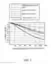
FIG. 2 is a Modulation Transfer Function (MTF) diagram showing several spatial frequency response curves in accordance with the optical lens module 10 of FIG. 1. Referring to FIG. 2, the modulation value in the MTF diagram substantially exceeds 0.4 when the spatial frequency is below 80 cycles/mm. This denotes that the optical lens module 10 of FIG. 1 has good resolving power and contrast.
Second Embodiment
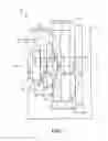
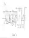
Referring to FIG. 3, the second embodiment of an optical lens module 10 has a configuration similar to the first embodiment (FIG. 1). However, the plane parallel plate L4 is omitted in FIG. 3. The optical lens module 10 primarily comprises a first lens L1, a second lens L2, and a third lens L3. Light can enter the first lens L1 from an object side and sequentially pass through the second lens L2, the third lens L3 to an image side. In this embodiment, an image sensing plane P of an imaging sensor, such as a CCD (Charge Coupled Device), is disposed on the image side of the lens module 10 to receive light.
As shown in FIG. 3, the first lens L1 may be a compound lens comprising three sub-lenses L11-L13. Similarly, the second lens L2 may be a compound lens comprising three sub-lenses L21-L23, and the third lens L3 may be a compound lens comprising three sub-lenses L31-L33. The sub-lenses L12, L22, and L32 may be plane parallel glass plates, and the other sub-lenses L11, L13, L21, L23, L31, and L33 may comprise curable resin material, such as transparent curable silicone resin or UV-curable material.
Specifically, an aperture stop is formed on the surface S3 between the sub-lenses L12 and L13 by wafer level processing. Since the aperture stop is securely fixed and embedded in the first lens L1 by wafer level processing, accurate positioning and robust connection between the aperture stop and the first lens L1 are achieved.
Table 2-1 and 2-2 illustrate the design parameters of the optical lens module 10 in FIG. 3, wherein the optical lens module 10 has a focal ratio F=2.8.
| TABLE 2-1 | ||||
| Radius | Abbe | |||
| Surface | of Curvature | Distance (mm) | Refractivity | Number |
| S1 | 1.02 | |||
| d1 = 0.26 | 1.514 | 55 | ||
| S2 | ∞ | |||
| d2 = 0.40 | 1.516 | 62.6 | ||
| S3 (aperture stop) | ∞ | |||
| d3 = 0.04 | 1.514 | 55 | ||
| S4 | 7.09 | |||
| d4 = 0.38 | ||||
| S5 | −1.08 | |||
| d5 = 0.02 | 1.596 | 29.5 | ||
| S6 | ∞ | |||
| d6 = 0.30 | 1.516 | 62.6 | ||
| S7 | ∞ | |||
| d7 = 0.30 | 1.596 | 29.5 | ||
| S8 | −0.80 | |||
| d8 = 0.02 | ||||
| S9 | −2.83 | |||
| d9 = 0.19 | 1.596 | 29.5 | ||
| S10 | ∞ | |||
| d10 = 0.70 | 1.516 | 62.6 | ||
| S11 | ∞ | |||
| d11 = 0.20 | 1.52 | 49.5 | ||
| S12 | 1.85 | |||
| d12 = 0.57 | ||||
| TABLE 2-2 | |
| Aspheric Coefficiencies |
| Surface | K | A4 | A6 | A8 | A10 | A12 | A14 | A16 |
| S1 | 0.59340904 | −0.098518181 | 0.136881087 | −1.367852035 | 2.866029943 | −3.531880715 | ||
| S2 | ||||||||
| S3 (aperture stop) | ||||||||
| S4 | −0.052231834 | −0.960150293 | 9.094109744 | −51.72644856 | 97.62887204 | |||
| S5 | −1.520016026 | −0.398174824 | −1.050751209 | 2.203085857 | 8.07797971 | −48.2366404 | ||
| S6 | ||||||||
| S7 | ||||||||
| S8 | −0.759397198 | 0.223016496 | 0.125163951 | 0.295573477 | 0.036553087 | −0.299417881 | ||
| S9 | 0.007127642 | 0.377724517 | −0.481724539 | 0.271485131 | −0.060765726 | |||
| S10 | ||||||||
| S11 | ||||||||
| S12 | −13.15426958 | −0.124603675 | 0.057709964 | −0.027493173 | 0.006715297 | −0.001587988 | 0.000535084 | −8.51E−05 |
As shown in FIG. 3, Tables 2-1 and 2-2, the first lens L1 of the optical lens module 10 has a convex surface (surface S1) and a concave surface (surface S4), respectively, on an object side and an image side thereof. The second lens L2 of the optical lens module 10 has a concave surface (surface S5) and a convex surface (surface S8), respectively, on an object side and an image side thereof. In this embodiment, the third lens L3 of the optical lens module 10 has a concave surface S9 on an object side thereof. Additionally, the third lens L3 further has a convex peripheral portion on an image side thereof. Referring to FIG. 1, the convex peripheral portion forms a surface S12 with a concave center on the image side, wherein the surface S12 has a deflection point. In some embodiments, the surface S9 of the third lens L3 can also be a convex surface.
The optical lens module 10 in FIG. 3 further complies with the conditions (1-1), (1-2), and (1-3) as disclosed in the first embodiment. FIG. 4 is a Modulation Transfer Function (MTF) diagram showing several spatial frequency response curves in accordance with the optical lens module 10 of FIG. 3. Referring to FIG. 4, the modulation value in the MTF diagram substantially exceeds 0.4 when the spatial frequency is below 100 cycles/mm. This denotes that the optical lens module 10 has good resolving power and contrast.
While the invention has been described by way of example and in terms of preferred embodiment, it is to be understood that the invention is not limited thereto. To the contrary, it is intended to cover various modifications and similar arrangements (as would be apparent to those skilled in the art). Therefore, the scope of the appended claims should be accorded the broadest interpretation to encompass all such modifications and similar arrangements.
Claims
What is claimed is:1. An optical lens module, comprising a first lens, a second lens, a third lens, and an aperture stop formed in the first lens by wafer level processing, wherein
the first lens, the second lens, and the third lens are sequentially arranged from an object side to an image side along an optical axis of the optical lens module,
the first lens has a convex surface and a concave surface, respectively, on the object side and the image side,
the second lens has a concave surface and a convex surface, respectively, on the object side and the image side, and
the third lens has a convex peripheral portion on the image side, wherein the convex peripheral portion forms a surface with a concave center on the image side, and the surface has a deflection point.
2. The optical lens module as claimed in claim 1, wherein the first lens is a compound lens comprising a first sub-lens, a second sub-lens, and a third sub-lens sequentially arranged from the object side to the image side along the optical axis, and the aperture stop is formed between the first and second sub-lenses.
3. The optical lens module as claimed in claim 2, wherein the first and third sub-lenses comprise curable resin material.
4. The optical lens module as claimed in claim 2, wherein the first and third sub-lenses comprise curable resin or UV-curable material.
5. The optical lens module as claimed in claim 2, wherein the second sub-lens is a parallel glass plate.
6. The optical lens module as claimed in claim 1, wherein the first lens is a compound lens comprising a first sub-lens, a second sub-lens, and a third sub-lens sequentially arranged from the object side to the image side along the optical axis, and the aperture stop is formed between the second and third sub-lenses.
7. The optical lens module as claimed in claim 6, wherein the first and third sub-lenses comprise curable resin material.
8. The optical lens module as claimed in claim 6, wherein the first and third sub-lenses comprise curable resin or UV-curable material.
9. The optical lens module as claimed in claim 6, wherein the second sub-lens is a parallel glass plate.
10. The optical lens module as claimed in claim 1, wherein the third lens further has a concave surface on the object side.
11. The optical lens module as claimed in claim 1, wherein the optical lens module defines an optical length L from the object side of the first lens to an image sensing plane along the optical axis, and the first and second lenses form a distance D12 therebetween along the optical axis, wherein 0.2>D12/L>0.05.
12. The optical lens module as claimed in claim 1, wherein the first lens has an effective focal length EFL1, and the second lens has an effective focal length EFL2, wherein 0.2<|EFL1|/|EFL2|<1.
13. The optical lens module as claimed in claim 1, wherein the first lens has an effective focal length EFL1, and the third lens has an effective focal length EFL3, wherein |EFL3|>|EFL1|.
14. The optical lens module as claimed in claim 1, wherein the optical lens module further comprises a plane parallel plate disposed on the image side of the third lens.
15. The optical lens module as claimed in claim 1, wherein the second and third lenses are compound lenses.
Images & Drawings included:
Sources:
- United States Patent and Trademark Office - verify current appl. status at the USPTO↗
Similar patent applications:
- » 20210373276
RETAINER, OPTICAL LENS MODULE HAVING THE RETAINER AND ELECTRONIC DEVICE HAVING THE OPTICAL LENS MODULE - » 20120147478
Varifocal lens structure, method of manufacturing the varifocal lens structure, optical lens module including the varifocal lens structure, and method of manufacturing the optical lens module - » 20090279186
Movable lens module and optical lens module - » 20220043231
OPTICAL LENS, LENS MODULE HAVING OPTICAL LENS, AND ELECTRONIC DEVICE - » 20240168297
OPTICAL LENS MODULE, OPTICAL ENGINE MODULE AND HEAD-MOUNTED DISPLAY - » 20210063674
LENS MODULE, OPTICAL LENS, AND ELECTRONIC DEVICE - » 20240168264
OPTICAL LENS MODULE, OPTICAL ENGINE MODULE AND HEAD-MOUNTED DISPLAY DEVICE - » 20160127701
Combined optical lens module and optical imaging device using the same - » 20180106978
Camera lens module with one or more optical lens modules and manufacturing method thereof - » 20190361191
Camera lens module with one or more optical lens modules and manufacturing method thereof
Recent applications in this class:
- » 20250164747 2025-05-22
IMAGE CAPTURING LENS - » 20250155679 2025-05-15
OPTICAL IMAGING SYSTEM - » 20250147281 2025-05-08
Lens Assembly - » 20250138282 2025-05-01
IMAGING LENS - » 20250130399 2025-04-24
OPTICAL SYSTEM AND OPTICAL CAMERA - » 20250102771 2025-03-27
IMAGING LENS ASSEMBLY, IMAGE CAPTURING UNIT AND ELECTRONIC DEVICE - » 20250093618 2025-03-20
CAMERA OPTICAL LENS - » 20250085510 2025-03-13
Lens Assembly - » 20250067959 2025-02-27
IMAGING LENS AND IMAGING APPARATUS - » 20250044554 2025-02-06
OPTICAL SYSTEM AND CAMERA MODULE COMPRISING SAME
Recent applications for this Assignee:
- » 20250287120 2025-09-11
Image Sensor Operating In A Reset Free Photovoltaic Mode - » 20250220317 2025-07-03
LOW-POWER ALWAYS-ON EVENT-BASED VISION SENSOR - » 20250217944 2025-07-03
Quad-Photodiode (QPD) Image Deblurring Using Convolutional Neural Network - » 20250211878 2025-06-26
ADAPTIVE DATA SELECTION FOR DCG / DAG - » 20250211871 2025-06-26
Image Sensor Operating In A Photovoltaic Mode - » 20250211870 2025-06-26
Image Sensor Having Pixels In LInear Mode and Photovoltaic Mode - » 20250159373 2025-05-15
Image Sensor and Optical Signal Generation Method - » 20250159372 2025-05-15
Image Sensor to Supress Flicker - » 20250150729 2025-05-08
Minimal Repeating Unit Having Reduced Blooming Effect of Clear Pixels - » 20250126373 2025-04-17
OPERATION METHOD TO MITIGATE LAG ISSUE WITH HIGH K METAL-INSULATOR-METAL (MIM) CAPACITOR